
Коды ошибок и сообщения бесперебойников
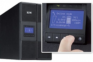
Источники бесперебойного питания нового поколения оснащены удобным ЖК-дисплеем для вывода информации о текущих параметрах энергосети и сообщений пользователю об ошибках, неисправностях и возможных неполадках с целью их оперативного устранения. Зная коды ошибок ИБП, владелец устройства сможет быстро среагировать на сообщение и предотвратить серьезные последствия любого сбоя.
Что такое события ИБП, и почему устройство пищит?
Интуитивно понятный интерфейс существенно упрощает «язык общения» бесперебойника с пользователем. Многие производители используют для типичных сообщений о состоянии ИБП не цифровые и буквенные коды, а условные обозначения. Нередко знаки на дисплее сопровождаются звуковыми сигналами бесперебойника. Если вы уже купили источник бесперебойного питания, инструкция по эксплуатации даст ответы на все вопросы о значении таких символов и кодов ошибок. Некоторые ситуации являются универсальными, встречающимися вне зависимости от марки производства устройства.
События – это фоновые условия, формой которых пользуются многие престижные марки ИБП (например, Eaton). Коды ошибок ИБП Eaton чередуются с регулярными сообщениями о событиях, которые регистрирует устройство как информацию о текущем состоянии. Такие уведомления сопровождаются звуковым сигналом, подаваемым с определенной периодичностью. Сигнал событий можно отключить – например, если вы поставили бесперебойник дома, и звук регулярных уведомлений мешает вашему досугу. Устройство будет сообщать о состоянии (работа от аккумулятора, переход на байпас, другие аспекты из журнала событий) через ЖК-дисплей. В отличие от кодов ошибок или предупреждений, события сообщают не о проблемах с бесперебойником, а о его исправной работе.
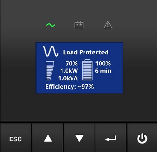
Что означают предупреждения ИБП?
Предупреждения, подаваемые при помощи символьных обозначений, мигания индикатора и звукового сигнала, свидетельствуют об определенной неисправности источника бесперебойного питания, или об угрозе.
-
Режим работы от батарей – сообщение, сопровождаемое непрерывной работой светодиодного индикатора и звуковым сигналом с промежутками времени в 5 секунд. Сообщает о сбое в энергосети, из-за чего ИБП перешел на питание от аккумулятора. Следует подготовить технику к выключению, сохранить все нужные документы – если это автоматически не предусмотрено используемым программным обеспечением.
-
Низкий заряд батареи – медленное мигание светодиода, посекундный звуковой сигнал. Это сообщение replace battery на бесперебойнике – о разряде батареи, оно может появляться на уровне заряда 25% и меньше.
-
Переход на байпас – горит индикатор-светодиод, каждые 5 секунд подается сигнал-звук. При переходе на байпас ИБП продолжает фильтровать энергию, но не защищает оборудование, так как батарейный режим работы недоступен. Причиной может служить перегрев, неисправность ИБП, перегрузка.
-
Если индикатор горит, но звукового сигнала нет – значит, ИБП перешел на байпас в высокоэффективном режиме работы. Оборудование находится под защитой, режим работы от АКБ доступен.
-
Сигнал отсоединения батарей сопровождается ежесекундным звуковым сообщением и продолжительным включением светодиода. Батареи действительно могут быть отсоединены – нужно проверить исправность подключения. Другой причиной может служить невозможность ИБП распознать батареи, что свидетельствует о неисправности ИБП, аккумуляторов, неправильного выбора аккумуляторов и других причинах ошибки.
-
Перегрузка, или overload на бесперебойнике – означает, что мощность ИБП меньше, чем возникшие требования к питанию. Необходимо отсоединить наименее приоритетную часть оборудования, иначе ИБП выключится от дальнейшего увеличения нагрузки, либо перейдет на байпас.
Во избежание перегрузки оборудование, которое не нуждается в постоянной защите (лазерные принтеры, плоттеры) рекомендуется подключать к выходам surge only на бесперебойнике. -
Перегрев – сигнал, подаваемый при чересчур высокой внутренней температуре источника. Возможно, отказал вентилятор. От момента подачи этого сообщения при повышении температуры еще на 10 градусов бесперейбоник переключается на режим байпаса, либо отключается, если работа на байпасе недоступна.
Чтобы устранить причины перегрева, следует очистить вентиляционные отверстия, перенести устройство подальше от источников тепла. Позаботьтесь об обеспечении беспрепятственного воздушного потока вокруг бесперебойника. Когда ИБП остынет, его можно перезапустить. Если проблема не решена, обращайтесь в сервисный центр. -
Слишком высокое напряжение АКБ – сигнал, сообщающий об отключении бесперебойником его зарядного устройства до запуска следующего цикла.
Некоторые значки на бесперебойнике просто сообщают о текущем состоянии устройства или о переходе из одного режима в другой, что не представляет собой сбоя или угрозы. Но если вы увидели сообщение об опасности, ошибке или неисправности ИБП, желательно обратиться к специалистам за сервисным обслуживанием устройства. Только профессионал сможет без негативных последствий устранить причины выхода из строя источника бесперебойного питания или отдельных его элементов.
Другие материалы по теме
18 мар. 2016
01 мар. 2016

02 дек. 2016
28 ноя. 2016

25 ноя. 2016

19 мар. 2016
Возврат к списку
Chapter 14
Typical Alarms and Conditions
Table 19. Troubleshooting Guide
Alarm or Condition
On Battery
LED is on.
1 beep every second.
Battery Low
LED is on.
Continuous beep for
10 seconds.
Battery Breaker
LED is on.
1 beep every second.
Overload
LED is on.
1 beep every second.
Overtemperature
LED is on.
1 beep every second.
Battery test failed
This section explains:
S
Typical UPS alarms and conditions
S
How to silence an alarm
S
Service and support
Table 19 describes typical alarms and conditions; check the Event Log through the
control panel for a list of active alarms. If an alarm appears with a service code, please
contact the Help Desk (see page 80).
Possible Cause
A utility failure has occurred and the UPS is in
Battery mode.
The battery is running low.
The UPS does not recognize the internal
batteries.
Power requirements exceed the UPS capacity
(greater than 100% of nominal; see page 75 for
specific output overload ranges).
UPS internal temperature is too high or the fan
has failed.
The batteries need service.
Eaton 9155 UPS (8–15 kVA) User’s Guide
Action
The UPS is powering the equipment with battery power. Prepare
your equipment for shutdown.
Five minutes or less of battery power remains (depending on load
configuration and battery charge). Save your work and turn off
your equipment.
When utility power is restored, the UPS restarts automatically,
provides power to the load, and charges the battery.
Verify the battery circuit breaker is in the ON position. If the
condition persists, contact your service representative.
Remove some of the equipment from the UPS. The UPS continues
to operate, but may switch to Bypass mode if the load increases.
The alarm resets when the condition becomes inactive.
If you have an optional Maintenance Bypass Module (MBM) or
Power Distribution Module (PDM), turn the maintenance bypass
switch to the SERVICE position. If you have a wall-mounted
bypass switch, turn the maintenance bypass switch to the LINE
position. Otherwise, shut down the UPS.
Clear vents and remove any heat sources. Allow the UPS to cool.
Ensure the airflow around the UPS is not restricted.
If the alarm disappears, turn the maintenance bypass switch back
to the UPS position (or restart the UPS if you do not have a
switch).
If the condition persists, contact your service representative.
Contact your service representative.
S
164201553 Rev G (www.eaton.com/powerquality)
79
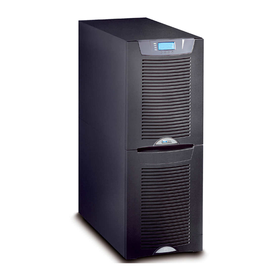
подробное описание кодов ошибок по Eaton
| Автор | Сообщение | |||||||||
|---|---|---|---|---|---|---|---|---|---|---|
|
Site Admin
Зарегистрирован: 06 апр 2005 08:14 |
Одно из самых полных описаний кодов неисправностей по различным комплектациям моторов, кпп и других компонентов. Данное издание подготовлено Eaton
|
|||||||||
| 22 июн 2012 17:04 |
|
|||||||||
 |
||||||||||
|
Antart Ф@Н@Т
Зарегистрирован: 15 апр 2010 08:48 Автомобиль/VIN: Диагностика, автоэлектрика, |
Ну и здесь на русском : http://tulatruck.ru/load/fajly_sajta/fa … 34-1-0-113 http://tulatruck.ru/load/fajly_sajta/fa … 34-1-0-114
|
|||||||||
| 22 июн 2012 18:45 |
|
|||||||||
|
||||||||||
|
Igor Site Admin
Зарегистрирован: 06 апр 2005 08:14 |
Что то я не найду куда там ткунть ??? Или надо регистрироваться ??? |
|||||||||
| 23 июн 2012 01:11 |
|
|||||||||
|
||||||||||
|
Lehers_rus Ф@Н@Т
Предупреждения: 1 Зарегистрирован: 09 дек 2011 12:36 Автомобиль/VIN: International 9800 |
можно ведь и сюда добавить. |
|||||||||
| 23 июн 2012 08:14 |
|
|||||||||
|
||||||||||
|
Миша Ф@Н@Т
Зарегистрирован: 27 окт 2006 19:31 Автомобиль/VIN: FREIGHTLINER FLD / 1FUBALCG44DN41138 |
Да походу надо регистрироватся, да ещё статус иметь, Андрей погорячился со ссылкой Добавлено спустя 8 минут 18 секунд: |
|||||||||
| 23 июн 2012 08:56 |
|
|||||||||
|
||||||||||
|
Antart Ф@Н@Т
Зарегистрирован: 15 апр 2010 08:48 Автомобиль/VIN: Диагностика, автоэлектрика, |
Не подумал что будут проблемы с просмотром… http://files.mail.ru/BHOZQ9 |
|||||||||
| 24 июн 2012 09:46 |
|
|||||||||
| Показать сообщения за: Поле сортировки |


 подробное описание кодов ошибок по Eaton









-
Contents
-
Table of Contents
-
Troubleshooting
-
Bookmarks
Quick Links
®
Eaton 9155 UPS
8–15 kVA
User’s Guide
Related Manuals for Eaton 9155
Summary of Contents for Eaton 9155
- Page 1
® Eaton 9155 UPS 8–15 kVA User’s Guide… - Page 2
Schneider Automation. National Electrical Code and NEC are registered trademarks of National Fire Protection Association, Inc. All other trademarks are property of their respective companies. ECopyright 2004–2011 Eaton Corporation, Raleigh, NC, USA. All rights reserved. No part of this document may be reproduced in any way without the express written approval of Eaton Corporation. - Page 3
89/336/EEC, Council Directive relating to electromagnetic compatibility 92/31/EEC, Amending Directive 89/336/EEC relating to EMC The EC Declaration of Conformity is available upon request for products with a CE mark. For copies of the EC Declaration of Conformity, contact: Eaton Power Quality Oy Koskelontie 13 FIN-02920 Espoo… -
Page 4: Special Symbols
Special Symbols The following are examples of symbols used on the UPS or accessories to alert you to important information: RISK OF ELECTRIC SHOCK — Observe the warning associated with the risk of electric shock symbol. CAUTION: REFER TO OPERATOR’S MANUAL — Refer to your operator’s manual for additional information, such as important operating and maintenance instructions.
-
Page 5: Table Of Contents
…………..164201553 Rev G (www.eaton.com/powerquality) Eaton 9155 UPS (8–15 kVA) User’s Guide…
- Page 6
……….164201553 Rev G (www.eaton.com/powerquality) Eaton 9155 UPS (8–15 kVA) User’s Guide… -
Page 7: Introduction
With the Eaton 9155, you can safely eliminate the effects of electrical line disturbances and guard the integrity of your systems and equipment. Figure 1 shows the Eaton 9155 UPS and an optional Extended Battery Module (EBM).
- Page 8
(CAN) Bridge Card provides connectivity for system metering and operational mode control. The parallel system consists of two to three UPSs, each with a parallel CAN Bridge Card, and a parallel tie cabinet. Refer to the Eaton 9155 Parallel UPS (8–15 kVA) User’s Guide for more information. -
Page 9: Safety Warnings
Keep unauthorized personnel away from batteries. Proper disposal of batteries is required. Refer to your local codes for disposal requirements. Never dispose of batteries in a fire. Batteries may explode when exposed to flame. 164201553 Rev G (www.eaton.com/powerquality) Eaton 9155 UPS (8–15 kVA) User’s Guide…
- Page 10
Une mise au rebut réglementaire des batteries est obligatoire. Consulter les règlements en vigueur dans votre localité. Ne jamais jeter les batteries au feu. L’exposition aux flammes risque de les faire exploser. 164201553 Rev G (www.eaton.com/powerquality) Eaton 9155 UPS (8–15 kVA) User’s Guide… -
Page 11: Advertencias De Seguridad
Es necesario desechar las baterías de un modo adecuado. Consulte las normas locales para conocer los requisitos pertinentes. Nunca deseche las baterías en el fuego. Las baterías pueden explotar si se las expone a la llama. 164201553 Rev G (www.eaton.com/powerquality) Eaton 9155 UPS (8–15 kVA) User’s Guide…
- Page 12
SAFETY WARNINGS 164201553 Rev G (www.eaton.com/powerquality) Eaton 9155 UPS (8–15 kVA) User’s Guide… -
Page 13: Ups Setup
2-High UPS 3-High UPS 2-High UPS with Maintenance Bypass Module (MBM) or Power Distribution Module (PDM) 3-High UPS with MBM/PDM 3-High UPS with Isolation Transformer 2-High EBM 3-High EBM 164201553 Rev G (www.eaton.com/powerquality) Eaton 9155 UPS (8–15 kVA) User’s Guide…
-
Page 14: Clearances
UPS SETUP Clearances The following clearances are recommended for the Eaton 9155 UPS: From Front of Cabinet 36” (91.4 cm) working space From Back of Cabinet 6” (15.2 cm) without an MBM/PDM installed; with an MBM/PDM installed, clearance is determined by the customer-supplied mating…
- Page 15
Figure 3. Removing the Brackets and Shipping Pad Reinstall the front cover removed in Step 3. Hang the top edge of the cover on the cabinet first, then lower the bottom edge and snap into place. 164201553 Rev G (www.eaton.com/powerquality) Eaton 9155 UPS (8–15 kVA) User’s Guide… - Page 16
Figure 4. Unloading the Cabinet With the cabinet supported, slowly pull the pallet away from the cabinet (see Figure 5). Figure 5. Removing the Pallet Roll the cabinet to the desired location. 164201553 Rev G (www.eaton.com/powerquality) Eaton 9155 UPS (8–15 kVA) User’s Guide… -
Page 17: Selecting An Installation Option
UPS SETUP Selecting an Installation Option You are now ready to install the Eaton 9155 UPS. Select one of the following installation options according to your UPS configuration: UPS Configuration Installation Chapter UPS only Chapter 4, “UPS Only Installation” on page 13 UPS with an optional input isolation Chapter 5, “Input Isolation Transformer Installation”…
- Page 18
UPS SETUP 164201553 Rev G (www.eaton.com/powerquality) Eaton 9155 UPS (8–15 kVA) User’s Guide… -
Page 19: Ups Only Installation
NOTE To accommodate the feature of easy system expandability, it is recommended that initial installation of the Eaton 9155 UPS contain wiring to support the maximum capacity of the UPS cabinet. Switch off utility power to the distribution point where the UPS will be connected.
- Page 20
See Table 1 for specifications and Figure 7 for a detailed view of the UPS terminal block. Replace the UPS wiring access cover. Continue to “Stabilizing the Cabinet” on page 43 to complete the UPS installation. 164201553 Rev G (www.eaton.com/powerquality) Eaton 9155 UPS (8–15 kVA) User’s Guide… -
Page 21: Ups Terminal Block Wiring
AWG size than shown in this table because of temperature, number of conductors in the conduit, or long service runs. Follow local requirements. 2 2A Input Output Figure 7. UPS Terminal Block 164201553 Rev G (www.eaton.com/powerquality) Eaton 9155 UPS (8–15 kVA) User’s Guide…
- Page 22
UPS ONLY INSTALLATION Figure 8. UPS Only Wiring Diagram 164201553 Rev G (www.eaton.com/powerquality) Eaton 9155 UPS (8–15 kVA) User’s Guide… -
Page 23: Input Isolation Transformer Installation
NOTE To accommodate the feature of easy system expandability, it is recommended that initial installation of the Eaton 9155 UPS contain wiring to support the maximum capacity of the UPS cabinet. Switch off utility power to the distribution point where the UPS will be connected.
- Page 24
11. Hardwire the input, output, and ground terminations for the input isolation transformer. See Table 2 for specifications and Figure 10 for a detailed view of the input isolation transformer terminal block. 164201553 Rev G (www.eaton.com/powerquality) Eaton 9155 UPS (8–15 kVA) User’s Guide… - Page 25
* Use only 75°C-rated copper wire. Minimum wire size is based on 120/208 full load ratings applied to NEC Code Table 310‐16. Code may require a larger AWG size than shown in this table because of temperature, number of conductors in the conduit, or long service runs. Follow local requirements. 164201553 Rev G (www.eaton.com/powerquality) Eaton 9155 UPS (8–15 kVA) User’s Guide… - Page 26
Greenlee punch or similar device (see Figure 10 on page 19). 16. Install the supplied edge grommet in the top of the input isolation transformer wiring cover. 164201553 Rev G (www.eaton.com/powerquality) Eaton 9155 UPS (8–15 kVA) User’s Guide… - Page 27
18. Punch a hole in the bottom of the MBM/PDM using a Greenlee punch or similar device for wiring access. Insert the supplied nylon bushing inside the wiring access hole. 19. Continue to the following chapter, “UPS-Mounted Bypass Switch Installation,” to complete the installation. 164201553 Rev G (www.eaton.com/powerquality) Eaton 9155 UPS (8–15 kVA) User’s Guide… - Page 28
INPUT ISOLATION TRANSFORMER INSTALLATION Figure 12. UPS with Input Isolation Transformer Wiring Diagram 164201553 Rev G (www.eaton.com/powerquality) Eaton 9155 UPS (8–15 kVA) User’s Guide… - Page 29
INPUT ISOLATION TRANSFORMER INSTALLATION Figure 13. UPS with Input Isolation Transformer and MBM/PDM Wiring Diagram 164201553 Rev G (www.eaton.com/powerquality) Eaton 9155 UPS (8–15 kVA) User’s Guide… - Page 30
INPUT ISOLATION TRANSFORMER INSTALLATION 164201553 Rev G (www.eaton.com/powerquality) Eaton 9155 UPS (8–15 kVA) User’s Guide… -
Page 31: Ups-Mounted Bypass Switch Installation
Remove the lowest top cover screw on each side of the UPS and discard. Lowest Top Cover Screw (one each side) Connecting Plate (8 screws) Figure 14. UPS Rear View (2-High Cabinet Shown) 164201553 Rev G (www.eaton.com/powerquality) Eaton 9155 UPS (8–15 kVA) User’s Guide…
- Page 32
UPS electronics unit through an access slot. UPS Electronics Unit MBM/PDM Wiring Access Cover Conduit Landing Plates Figure 16. Installing the MBM or PDM (MBM Shown) 164201553 Rev G (www.eaton.com/powerquality) Eaton 9155 UPS (8–15 kVA) User’s Guide… - Page 33
Step 1. Continue to the following section, “Wiring the MBM/PDM.” Screws for Top of Module Screws to L-Bracket (three each side) Figure 17. Securing the MBM or PDM (MBM Shown) 164201553 Rev G (www.eaton.com/powerquality) Eaton 9155 UPS (8–15 kVA) User’s Guide… -
Page 34: Wiring The Mbm/Pdm
NOTE To accommodate the feature of easy system expandability, it is recommended that initial installation of the Eaton 9155 UPS contain wiring to support the maximum capacity of the UPS cabinet. Switch off utility power to the distribution point where the UPS will be connected.
- Page 35
Hardwire the input, output, and ground terminations for the MBM/PDM. See Table 4 for specifications and Figure 19 for a detailed view of the MBM/PDM terminal block. TB10 Figure 19. MBM/PDM Hardwiring (PDM Shown) 164201553 Rev G (www.eaton.com/powerquality) Eaton 9155 UPS (8–15 kVA) User’s Guide… - Page 36
Connect the maintenance bypass (red and black) wires to TB1-2 (the A/B maintenance bypass auxiliary contacts) on the UPS terminal block. Input Output A/B Maintenance Bypass Auxiliary Contacts Figure 20. Wiring from Maintenance Bypass Switch to UPS 164201553 Rev G (www.eaton.com/powerquality) Eaton 9155 UPS (8–15 kVA) User’s Guide… - Page 37
Replace the wiring access cover on the UPS and the optional isolation transformer, if applicable. 10. Replace the MBM/PDM wiring access cover and conduit landing plate. 11. Continue to “Stabilizing the Cabinet” on page 43 to complete the installation. 164201553 Rev G (www.eaton.com/powerquality) Eaton 9155 UPS (8–15 kVA) User’s Guide… - Page 38
UPS-MOUNTED BYPASS SWITCH INSTALLATION Figure 21. UPS with MBM Wiring Diagram 164201553 Rev G (www.eaton.com/powerquality) Eaton 9155 UPS (8–15 kVA) User’s Guide… - Page 39
UPS-MOUNTED BYPASS SWITCH INSTALLATION Figure 22. UPS with PDM Wiring Diagram 164201553 Rev G (www.eaton.com/powerquality) Eaton 9155 UPS (8–15 kVA) User’s Guide… - Page 40
UPS-MOUNTED BYPASS SWITCH INSTALLATION 164201553 Rev G (www.eaton.com/powerquality) Eaton 9155 UPS (8–15 kVA) User’s Guide… -
Page 41: Wall-Mounted Bypass Switch Installation
21.0” (53.4 cm) Width 14.0” (35.6 cm) Depth 6.8” (17.2 cm) Mounting 11.0” (28.0 cm) Centers 20.0” (50.8 cm) Weight 31 lb (14.1 kg) Figure 23. Wall-Mounted Bypass Switch Dimensions 164201553 Rev G (www.eaton.com/powerquality) Eaton 9155 UPS (8–15 kVA) User’s Guide…
-
Page 42: Wall-Mounted Bypass Switch Setup
Remove the six screws from the bypass switch front cover and remove the cover (see Figure 24). Remove and discard any packing material from inside the bypass switch. 164201553 Rev G (www.eaton.com/powerquality) Eaton 9155 UPS (8–15 kVA) User’s Guide…
-
Page 43: Wiring The Wall-Mounted Bypass Switch
NOTE To accommodate the feature of easy system expandability, it is recommended that initial installation of the Eaton 9155 UPS contain wiring to support the maximum capacity of the UPS cabinet. Switch off utility power to the distribution point where the bypass switch cabinet and UPS will be connected.
- Page 44
See Figure 26 for a detailed view of the terminal strip label. Figure 26. Wall-Mounted Bypass Switch Terminal Strip Wiring 164201553 Rev G (www.eaton.com/powerquality) Eaton 9155 UPS (8–15 kVA) User’s Guide… - Page 45
AWG size than shown in this table because of temperature, number of conductors in the conduit, or long service runs. Follow local requirements. 2 2A Input Output Figure 27. UPS Terminal Block 164201553 Rev G (www.eaton.com/powerquality) Eaton 9155 UPS (8–15 kVA) User’s Guide… - Page 46
Do Not Connect Red and Black Wires To UPS Terminal Block Signal Cable Figure 28. Signal Cable Installation 11. Replace the bypass switch front cover and the UPS wiring access cover. 164201553 Rev G (www.eaton.com/powerquality) Eaton 9155 UPS (8–15 kVA) User’s Guide… - Page 47
WALL-MOUNTED BYPASS SWITCH INSTALLATION Figure 29. UPS with Wall-Mounted Bypass Switch Wiring Diagram 164201553 Rev G (www.eaton.com/powerquality) Eaton 9155 UPS (8–15 kVA) User’s Guide… - Page 48
WALL-MOUNTED BYPASS SWITCH INSTALLATION 164201553 Rev G (www.eaton.com/powerquality) Eaton 9155 UPS (8–15 kVA) User’s Guide… -
Page 49: Stabilizing The Cabinet
Chapter 8 Stabilizing the Cabinet NOTE For seismic installations, you MUST order and install an Eaton 9155 UPS seismic kit; do not use the following instructions. NOTE For non-seismic installations, you MUST install the stabilizing bracket on all 3-high cabinets. The stabilizing bracket is optional for 2-high cabinets.
- Page 50
STABILIZING THE CABINET M4 Screws Figure 31. Stabilizing Bracket with One Cabinet M4 Screws Figure 32. Stabilizing Bracket with Two Cabinets 164201553 Rev G (www.eaton.com/powerquality) Eaton 9155 UPS (8–15 kVA) User’s Guide… - Page 51
STABILIZING THE CABINET M4 Screws Figure 33. Stabilizing Bracket with Three Cabinets 164201553 Rev G (www.eaton.com/powerquality) Eaton 9155 UPS (8–15 kVA) User’s Guide… - Page 52
STABILIZING THE CABINET 164201553 Rev G (www.eaton.com/powerquality) Eaton 9155 UPS (8–15 kVA) User’s Guide… -
Page 53: Extended Battery Module Installation
EBM. Repeat for each additional EBM. EBM Battery Circuit Breaker Rear Ground Strap EBM Battery Connector UPS Battery Connector UPS Battery Circuit Breaker Cable Figure 34. Typical EBM Installation (2-High Cabinets Shown) 164201553 Rev G (www.eaton.com/powerquality) Eaton 9155 UPS (8–15 kVA) User’s Guide…
- Page 54
NOTE After UPS startup, ensure maximum battery runtime by configuring the UPS for the correct number of EBMs (see page 64). Front Ground Strap Figure 35. Front Ground Strap Installation (2-High Cabinets Shown) 164201553 Rev G (www.eaton.com/powerquality) Eaton 9155 UPS (8–15 kVA) User’s Guide… -
Page 55: Communication
Signal Input 1 X-Slot Communication Bay #2 Signal Input 2 REPO (normally open) REPO (normally closed) DB-9 Communication Port Relay Output Contacts Figure 36. Communication Options and Control Terminals 164201553 Rev G (www.eaton.com/powerquality) Eaton 9155 UPS (8–15 kVA) User’s Guide…
-
Page 56: Installing Communication Options And Control Terminals
With wire cutters, cut either side of the tab and twist down to remove the tab (see Figure 39). 164201553 Rev G (www.eaton.com/powerquality) Eaton 9155 UPS (8–15 kVA) User’s Guide…
- Page 57
Be sure the cables fit in the access holes in the covers. Continue to “Operation” on page 57 to start up the UPS. Figure 40. Reinstalling the Front Covers 164201553 Rev G (www.eaton.com/powerquality) Eaton 9155 UPS (8–15 kVA) User’s Guide… -
Page 58: Communication Options
COMMUNICATION Communication Options The Eaton 9155 has serial communication capabilities through the DB-9 communication port or through an X-Slot card in one of the available bays. In addition, the LanSafe Power Management Software can be installed and used to communicate with the UPS via one of the serial communication connections.
-
Page 59: X-Slot Cards
USB Card — connects to a USB port on your computer. NOTE The Eaton 9155 does not detect plug-and-play hardware. Before installing the USB Card, set the UPS baud rate to 1200 through the front panel (see Table 9 on page 59).
-
Page 60: Lansafe Power Management Software
COMMUNICATION LanSafe Power Management Software Each Eaton 9155 UPS ships with LanSafe Power Management Software and an interface cable. To begin installing LanSafe software, see the instructions accompanying the Software Suite CD. NOTE Use only the supplied communication cable to connect the UPS to your computer.
-
Page 61: Remote Emergency Power-Off
The relay output contacts must not be connected to any utility connected circuits. Reinforced insulation to the utility is required. The relay output contacts have a maximum rating of 30 Vac/1A and 60 Vdc/2A nominal values. 164201553 Rev G (www.eaton.com/powerquality) Eaton 9155 UPS (8–15 kVA) User’s Guide…
-
Page 62: Programmable Signal Inputs
If active, the UPS knows that input is fed from the generator. Bypass is disabled; the automatic battery test is disabled. External Transformer This option is not used. Overtemperature 164201553 Rev G (www.eaton.com/powerquality) Eaton 9155 UPS (8–15 kVA) User’s Guide…
-
Page 63: Operation
Chapter 11 Operation This chapter contains information on how to use the Eaton 9155, including front panel operation, UPS startup and shutdown, operation of the maintenance bypass switch, and configuring the UPS for Extended Battery Modules (EBMs). Control Panel Functions The UPS has a four-button graphical LCD with backlight.
-
Page 64: Changing The Language
Display Functions As the default or after 15 minutes of inactivity, the LCD displays the selectable startup screen. The default is the Eaton logo and can be changed to the Mimic screen in the User Settings menu. The backlit LCD automatically dims after a long period of inactivity. Press any button to restore the screen.
-
Page 65: User Settings
(see “Programmable Signal Inputs” on page 56) Serial Port Config Port: [X-Slot-1] [X-Slot-2/Serv] 19200 Speed: [19200] [9600] [2400] [1200] Parallel Operation Settings Refer to the Eaton 9155 Parallel UPS (8–15 kVA) User’s Guide. Modem Config Modem Installation <Not Installed> Set Modem Call Events Event #0…
- Page 66
1 through 65535 seconds 120s Site Wiring Fault Notice Enabled/Disabled Enabled Reset Custom Event Settings 0 through 32 Total: 0/32 Auto Output Configuration Enabled/Disabled Enabled for initial startup Disabled after initial startup 164201553 Rev G (www.eaton.com/powerquality) Eaton 9155 UPS (8–15 kVA) User’s Guide… -
Page 67: Ups Startup
UPS with an optional wall-mounted bypass switch “Wall-Mounted Maintenance Bypass Startup” on page 64 Parallel UPS configuration Refer to the Eaton 9155 Parallel UPS (8–15 kVA) User’s Guide Normal Mode Startup To start up the UPS: If you have an optional MBM/PDM or wall-mounted bypass switch, verify that the maintenance bypass switch is in the UPS position (see Figure 45 on page 68 or Figure 48 on page 72).
-
Page 68: Starting The Ups On Battery
Confirm the selection. Press and hold the button for three seconds, until the UPS stops beeping. The UPS starts in Battery mode within two minutes and supplies battery power to your equipment. 164201553 Rev G (www.eaton.com/powerquality) Eaton 9155 UPS (8–15 kVA) User’s Guide…
-
Page 69: Internal Bypass Startup
Switch on utility power where the UPS is connected. The load is now powered by utility power. To transfer the load to the UPS, see “Using the UPS-Mounted Maintenance Bypass Switch” on page 68. 164201553 Rev G (www.eaton.com/powerquality) Eaton 9155 UPS (8–15 kVA) User’s Guide…
-
Page 70: Wall-Mounted Maintenance Bypass Startup
* UPS-32 models contain 2 strings; EBM-64 models contain 4 strings. UPS-64 models contain 4 strings; EBM-96 models contain 6 strings. Press the button to save the setting. Press the button until the Eaton logo appears. 164201553 Rev G (www.eaton.com/powerquality) Eaton 9155 UPS (8–15 kVA) User’s Guide…
-
Page 71: Ups Shutdown
Switch the UPS battery circuit breaker to the OFF position. The UPS is disconnected from the batteries and is on logic power only. Switch off utility power where the UPS is connected. 164201553 Rev G (www.eaton.com/powerquality) Eaton 9155 UPS (8–15 kVA) User’s Guide…
- Page 72
OPERATION 164201553 Rev G (www.eaton.com/powerquality) Eaton 9155 UPS (8–15 kVA) User’s Guide… -
Page 73: Ups Maintenance
Check the battery recharge date on the shipping carton label. If the date has expired and the batteries were never recharged, do not use the UPS. Contact your service representative. 164201553 Rev G (www.eaton.com/powerquality) Eaton 9155 UPS (8–15 kVA) User’s Guide…
-
Page 74: When To Replace Batteries
The UPS-mounted maintenance bypass switch is part of the optional Maintenance Bypass Module (MBM) or Power Distribution Module (PDM) and is located on the back of the UPS (see Figure 45). Figure 45. Maintenance Bypass Switch (PDM Shown) 164201553 Rev G (www.eaton.com/powerquality) Eaton 9155 UPS (8–15 kVA) User’s Guide…
- Page 75
Figure 46 shows a UPS with a separate battery cabinet and a UPS-mounted bypass switch. UPS-Mounted Bypass Switch Bypass User-Supplied Service Building Load Service Distribution Panel Panel Bypass Service Bypass Service Figure 46. Typical Hardwired Installation with UPS-Mounted Bypass Switch 164201553 Rev G (www.eaton.com/powerquality) Eaton 9155 UPS (8–15 kVA) User’s Guide… -
Page 76: Using The Wall-Mounted Bypass Switch
UPS, this is the appropriate position for UPS maintenance or repair. Disconnects the load from the UPS output power and AC input power, as well as AC input power to the UPS input. 164201553 Rev G (www.eaton.com/powerquality) Eaton 9155 UPS (8–15 kVA) User’s Guide…
- Page 77
Figure 47 shows a UPS with a separate battery cabinet and a wall-mounted bypass switch. Wall-Mounted Bypass Switch Service Line Building Load Service Distribution Panel Panel Service Line Service Line User-Supplied Figure 47. Typical Hardwired Installation with Wall-Mounted Bypass Switch 164201553 Rev G (www.eaton.com/powerquality) Eaton 9155 UPS (8–15 kVA) User’s Guide… - Page 78
Step 3; otherwise, power to the load may be lost. Turn the maintenance bypass switch to the UPS position to return to Normal mode. The UPS is now powering the load. 164201553 Rev G (www.eaton.com/powerquality) Eaton 9155 UPS (8–15 kVA) User’s Guide… -
Page 79: Specifications
3-high: UPS with one battery & one input isolation transformer section PW9155-15-64 3-high: UPS with two battery sections 15 kVA, 13.5 kW Extended Battery Description Module (EBM) PW9155-EBM-64 2-high: two battery sections PW9155-EBM-96 3-high: three battery sections 164201553 Rev G (www.eaton.com/powerquality) Eaton 9155 UPS (8–15 kVA) User’s Guide…
- Page 80
NOM-019-SCFI, UL 1778, CSA C22.2, No. 107.3; EN 55022 Class A (CISPR22 Class A) and IEC 60950; IEC 62040-1-1 Agency Markings cULus, cUL, CE, NOM-NYCE EMC (Class A) IEC 62040-2, FCC Part 15, ICES-003, VCCI 164201553 Rev G (www.eaton.com/powerquality) Eaton 9155 UPS (8–15 kVA) User’s Guide… - Page 81
Output Peak Current Efficiency (Minimum) Power Dissipation (BTU/hr) 5582 5582 5582 5582 5582 DC Voltage (Supply) * Input current for the input isolation transformer is 4% higher than for the UPS. 164201553 Rev G (www.eaton.com/powerquality) Eaton 9155 UPS (8–15 kVA) User’s Guide… - Page 82
Output Peak Current Efficiency (Minimum) Power Dissipation (BTU/hr) 3300 3300 3300 3300 3300 DC Voltage (Supply) * Input current for the input isolation transformer is 4% higher than for the UPS. 164201553 Rev G (www.eaton.com/powerquality) Eaton 9155 UPS (8–15 kVA) User’s Guide… -
Page 83: Battery Specifications
+3 EBM-96 Batteries 15 kVA/13.5 kW 12 kVA/10.8 kW 10 kVA/9 kW 8 kVA/7.2 kW NOTE Battery times are approximate and vary depending on the load configuration and battery charge. 164201553 Rev G (www.eaton.com/powerquality) Eaton 9155 UPS (8–15 kVA) User’s Guide…
- Page 84
SPECIFICATIONS 164201553 Rev G (www.eaton.com/powerquality) Eaton 9155 UPS (8–15 kVA) User’s Guide… -
Page 85: Troubleshooting
UPS position (or restart the UPS if you do not have a switch). If the condition persists, contact your service representative. Battery test failed The batteries need service. Contact your service representative. 164201553 Rev G (www.eaton.com/powerquality) Eaton 9155 UPS (8–15 kVA) User’s Guide…
-
Page 86: Silencing The Alarm
Please have the following information ready when you call for service: Model number Serial number Firmware version number Date of failure or problem Symptoms of failure or problem Customer return address and contact information 164201553 Rev G (www.eaton.com/powerquality) Eaton 9155 UPS (8–15 kVA) User’s Guide…
-
Page 87: Warranty
3.1 kVA ® WARRANTOR: The warrantor for the limited warranties set forth herein is Eaton Corporation Inc. or its subsidiaries and affiliates. Corporation, an Ohio Corporation company (“Company”). LIMITED WARRANTY: This limited warranty (this “Warranty”) applies only to the original End-User (the “End-User”) of any Eaton 9120, 9125, 9130, 9135, 9140, and FERRUPS up to 3.1 kVA Products (individually and collectively, the “Product”) purchased on or after June 1, 2004, and…
-
Page 88: Load Protection Guarantee (Us And Canada)
This load protection guaranty (this “Guaranty”) applies only to the original End-User (the “End-User”) of any Eaton 3105, 5110, 5115, 5125, 5130, 9120, 9125, 9130, 9135, 9140, 9150, 9155, 9170+, and FERRUPS Products (individually and collectively, the “Product”) and cannot be transferred. This Guaranty applies even in the event that the Product is initially sold by Company for resale to an End-User.
- Page 89
TO MAKE A CLAIM: In the USA, call the Customer Reliability Center 7×24 at 800-356-5737. Outside of the USA, contact your local Eaton product sales or service representative. For comments or questions about this Load Protection Guaranty, write to the Customer Quality Representative, 3301 Spring Forest Road, Raleigh, North Carolina 27616 USA. - Page 90
WARRANTY 164201553 Rev G (www.eaton.com/powerquality) Eaton 9155 UPS (8–15 kVA) User’s Guide… - Page 92
*164201553G* 164201553 G…
-
Contents
-
Table of Contents
-
Troubleshooting
-
Bookmarks
Quick Links
®
Eaton 9155 UPS
8–15 kVA
User’s Guide
Related Manuals for Eaton 9155
Summary of Contents for Eaton 9155
- Page 1
® Eaton 9155 UPS 8–15 kVA User’s Guide… - Page 2
Schneider Automation. National Electrical Code and NEC are registered trademarks of National Fire Protection Association, Inc. All other trademarks are property of their respective companies. ECopyright 2004–2011 Eaton Corporation, Raleigh, NC, USA. All rights reserved. No part of this document may be reproduced in any way without the express written approval of Eaton Corporation. - Page 3
89/336/EEC, Council Directive relating to electromagnetic compatibility 92/31/EEC, Amending Directive 89/336/EEC relating to EMC The EC Declaration of Conformity is available upon request for products with a CE mark. For copies of the EC Declaration of Conformity, contact: Eaton Power Quality Oy Koskelontie 13 FIN-02920 Espoo… -
Page 4: Special Symbols
Special Symbols The following are examples of symbols used on the UPS or accessories to alert you to important information: RISK OF ELECTRIC SHOCK — Observe the warning associated with the risk of electric shock symbol. CAUTION: REFER TO OPERATOR’S MANUAL — Refer to your operator’s manual for additional information, such as important operating and maintenance instructions.
-
Page 5: Table Of Contents
…………..164201553 Rev G (www.eaton.com/powerquality) Eaton 9155 UPS (8–15 kVA) User’s Guide…
- Page 6
……….164201553 Rev G (www.eaton.com/powerquality) Eaton 9155 UPS (8–15 kVA) User’s Guide… -
Page 7: Introduction
With the Eaton 9155, you can safely eliminate the effects of electrical line disturbances and guard the integrity of your systems and equipment. Figure 1 shows the Eaton 9155 UPS and an optional Extended Battery Module (EBM).
- Page 8
(CAN) Bridge Card provides connectivity for system metering and operational mode control. The parallel system consists of two to three UPSs, each with a parallel CAN Bridge Card, and a parallel tie cabinet. Refer to the Eaton 9155 Parallel UPS (8–15 kVA) User’s Guide for more information. -
Page 9: Safety Warnings
Keep unauthorized personnel away from batteries. Proper disposal of batteries is required. Refer to your local codes for disposal requirements. Never dispose of batteries in a fire. Batteries may explode when exposed to flame. 164201553 Rev G (www.eaton.com/powerquality) Eaton 9155 UPS (8–15 kVA) User’s Guide…
- Page 10
Une mise au rebut réglementaire des batteries est obligatoire. Consulter les règlements en vigueur dans votre localité. Ne jamais jeter les batteries au feu. L’exposition aux flammes risque de les faire exploser. 164201553 Rev G (www.eaton.com/powerquality) Eaton 9155 UPS (8–15 kVA) User’s Guide… -
Page 11: Advertencias De Seguridad
Es necesario desechar las baterías de un modo adecuado. Consulte las normas locales para conocer los requisitos pertinentes. Nunca deseche las baterías en el fuego. Las baterías pueden explotar si se las expone a la llama. 164201553 Rev G (www.eaton.com/powerquality) Eaton 9155 UPS (8–15 kVA) User’s Guide…
- Page 12
SAFETY WARNINGS 164201553 Rev G (www.eaton.com/powerquality) Eaton 9155 UPS (8–15 kVA) User’s Guide… -
Page 13: Ups Setup
2-High UPS 3-High UPS 2-High UPS with Maintenance Bypass Module (MBM) or Power Distribution Module (PDM) 3-High UPS with MBM/PDM 3-High UPS with Isolation Transformer 2-High EBM 3-High EBM 164201553 Rev G (www.eaton.com/powerquality) Eaton 9155 UPS (8–15 kVA) User’s Guide…
-
Page 14: Clearances
UPS SETUP Clearances The following clearances are recommended for the Eaton 9155 UPS: From Front of Cabinet 36” (91.4 cm) working space From Back of Cabinet 6” (15.2 cm) without an MBM/PDM installed; with an MBM/PDM installed, clearance is determined by the customer-supplied mating…
- Page 15
Figure 3. Removing the Brackets and Shipping Pad Reinstall the front cover removed in Step 3. Hang the top edge of the cover on the cabinet first, then lower the bottom edge and snap into place. 164201553 Rev G (www.eaton.com/powerquality) Eaton 9155 UPS (8–15 kVA) User’s Guide… - Page 16
Figure 4. Unloading the Cabinet With the cabinet supported, slowly pull the pallet away from the cabinet (see Figure 5). Figure 5. Removing the Pallet Roll the cabinet to the desired location. 164201553 Rev G (www.eaton.com/powerquality) Eaton 9155 UPS (8–15 kVA) User’s Guide… -
Page 17: Selecting An Installation Option
UPS SETUP Selecting an Installation Option You are now ready to install the Eaton 9155 UPS. Select one of the following installation options according to your UPS configuration: UPS Configuration Installation Chapter UPS only Chapter 4, “UPS Only Installation” on page 13 UPS with an optional input isolation Chapter 5, “Input Isolation Transformer Installation”…
- Page 18
UPS SETUP 164201553 Rev G (www.eaton.com/powerquality) Eaton 9155 UPS (8–15 kVA) User’s Guide… -
Page 19: Ups Only Installation
NOTE To accommodate the feature of easy system expandability, it is recommended that initial installation of the Eaton 9155 UPS contain wiring to support the maximum capacity of the UPS cabinet. Switch off utility power to the distribution point where the UPS will be connected.
- Page 20
See Table 1 for specifications and Figure 7 for a detailed view of the UPS terminal block. Replace the UPS wiring access cover. Continue to “Stabilizing the Cabinet” on page 43 to complete the UPS installation. 164201553 Rev G (www.eaton.com/powerquality) Eaton 9155 UPS (8–15 kVA) User’s Guide… -
Page 21: Ups Terminal Block Wiring
AWG size than shown in this table because of temperature, number of conductors in the conduit, or long service runs. Follow local requirements. 2 2A Input Output Figure 7. UPS Terminal Block 164201553 Rev G (www.eaton.com/powerquality) Eaton 9155 UPS (8–15 kVA) User’s Guide…
- Page 22
UPS ONLY INSTALLATION Figure 8. UPS Only Wiring Diagram 164201553 Rev G (www.eaton.com/powerquality) Eaton 9155 UPS (8–15 kVA) User’s Guide… -
Page 23: Input Isolation Transformer Installation
NOTE To accommodate the feature of easy system expandability, it is recommended that initial installation of the Eaton 9155 UPS contain wiring to support the maximum capacity of the UPS cabinet. Switch off utility power to the distribution point where the UPS will be connected.
- Page 24
11. Hardwire the input, output, and ground terminations for the input isolation transformer. See Table 2 for specifications and Figure 10 for a detailed view of the input isolation transformer terminal block. 164201553 Rev G (www.eaton.com/powerquality) Eaton 9155 UPS (8–15 kVA) User’s Guide… - Page 25
* Use only 75°C-rated copper wire. Minimum wire size is based on 120/208 full load ratings applied to NEC Code Table 310‐16. Code may require a larger AWG size than shown in this table because of temperature, number of conductors in the conduit, or long service runs. Follow local requirements. 164201553 Rev G (www.eaton.com/powerquality) Eaton 9155 UPS (8–15 kVA) User’s Guide… - Page 26
Greenlee punch or similar device (see Figure 10 on page 19). 16. Install the supplied edge grommet in the top of the input isolation transformer wiring cover. 164201553 Rev G (www.eaton.com/powerquality) Eaton 9155 UPS (8–15 kVA) User’s Guide… - Page 27
18. Punch a hole in the bottom of the MBM/PDM using a Greenlee punch or similar device for wiring access. Insert the supplied nylon bushing inside the wiring access hole. 19. Continue to the following chapter, “UPS-Mounted Bypass Switch Installation,” to complete the installation. 164201553 Rev G (www.eaton.com/powerquality) Eaton 9155 UPS (8–15 kVA) User’s Guide… - Page 28
INPUT ISOLATION TRANSFORMER INSTALLATION Figure 12. UPS with Input Isolation Transformer Wiring Diagram 164201553 Rev G (www.eaton.com/powerquality) Eaton 9155 UPS (8–15 kVA) User’s Guide… - Page 29
INPUT ISOLATION TRANSFORMER INSTALLATION Figure 13. UPS with Input Isolation Transformer and MBM/PDM Wiring Diagram 164201553 Rev G (www.eaton.com/powerquality) Eaton 9155 UPS (8–15 kVA) User’s Guide… - Page 30
INPUT ISOLATION TRANSFORMER INSTALLATION 164201553 Rev G (www.eaton.com/powerquality) Eaton 9155 UPS (8–15 kVA) User’s Guide… -
Page 31: Ups-Mounted Bypass Switch Installation
Remove the lowest top cover screw on each side of the UPS and discard. Lowest Top Cover Screw (one each side) Connecting Plate (8 screws) Figure 14. UPS Rear View (2-High Cabinet Shown) 164201553 Rev G (www.eaton.com/powerquality) Eaton 9155 UPS (8–15 kVA) User’s Guide…
- Page 32
UPS electronics unit through an access slot. UPS Electronics Unit MBM/PDM Wiring Access Cover Conduit Landing Plates Figure 16. Installing the MBM or PDM (MBM Shown) 164201553 Rev G (www.eaton.com/powerquality) Eaton 9155 UPS (8–15 kVA) User’s Guide… - Page 33
Step 1. Continue to the following section, “Wiring the MBM/PDM.” Screws for Top of Module Screws to L-Bracket (three each side) Figure 17. Securing the MBM or PDM (MBM Shown) 164201553 Rev G (www.eaton.com/powerquality) Eaton 9155 UPS (8–15 kVA) User’s Guide… -
Page 34: Wiring The Mbm/Pdm
NOTE To accommodate the feature of easy system expandability, it is recommended that initial installation of the Eaton 9155 UPS contain wiring to support the maximum capacity of the UPS cabinet. Switch off utility power to the distribution point where the UPS will be connected.
- Page 35
Hardwire the input, output, and ground terminations for the MBM/PDM. See Table 4 for specifications and Figure 19 for a detailed view of the MBM/PDM terminal block. TB10 Figure 19. MBM/PDM Hardwiring (PDM Shown) 164201553 Rev G (www.eaton.com/powerquality) Eaton 9155 UPS (8–15 kVA) User’s Guide… - Page 36
Connect the maintenance bypass (red and black) wires to TB1-2 (the A/B maintenance bypass auxiliary contacts) on the UPS terminal block. Input Output A/B Maintenance Bypass Auxiliary Contacts Figure 20. Wiring from Maintenance Bypass Switch to UPS 164201553 Rev G (www.eaton.com/powerquality) Eaton 9155 UPS (8–15 kVA) User’s Guide… - Page 37
Replace the wiring access cover on the UPS and the optional isolation transformer, if applicable. 10. Replace the MBM/PDM wiring access cover and conduit landing plate. 11. Continue to “Stabilizing the Cabinet” on page 43 to complete the installation. 164201553 Rev G (www.eaton.com/powerquality) Eaton 9155 UPS (8–15 kVA) User’s Guide… - Page 38
UPS-MOUNTED BYPASS SWITCH INSTALLATION Figure 21. UPS with MBM Wiring Diagram 164201553 Rev G (www.eaton.com/powerquality) Eaton 9155 UPS (8–15 kVA) User’s Guide… - Page 39
UPS-MOUNTED BYPASS SWITCH INSTALLATION Figure 22. UPS with PDM Wiring Diagram 164201553 Rev G (www.eaton.com/powerquality) Eaton 9155 UPS (8–15 kVA) User’s Guide… - Page 40
UPS-MOUNTED BYPASS SWITCH INSTALLATION 164201553 Rev G (www.eaton.com/powerquality) Eaton 9155 UPS (8–15 kVA) User’s Guide… -
Page 41: Wall-Mounted Bypass Switch Installation
21.0” (53.4 cm) Width 14.0” (35.6 cm) Depth 6.8” (17.2 cm) Mounting 11.0” (28.0 cm) Centers 20.0” (50.8 cm) Weight 31 lb (14.1 kg) Figure 23. Wall-Mounted Bypass Switch Dimensions 164201553 Rev G (www.eaton.com/powerquality) Eaton 9155 UPS (8–15 kVA) User’s Guide…
-
Page 42: Wall-Mounted Bypass Switch Setup
Remove the six screws from the bypass switch front cover and remove the cover (see Figure 24). Remove and discard any packing material from inside the bypass switch. 164201553 Rev G (www.eaton.com/powerquality) Eaton 9155 UPS (8–15 kVA) User’s Guide…
-
Page 43: Wiring The Wall-Mounted Bypass Switch
NOTE To accommodate the feature of easy system expandability, it is recommended that initial installation of the Eaton 9155 UPS contain wiring to support the maximum capacity of the UPS cabinet. Switch off utility power to the distribution point where the bypass switch cabinet and UPS will be connected.
- Page 44
See Figure 26 for a detailed view of the terminal strip label. Figure 26. Wall-Mounted Bypass Switch Terminal Strip Wiring 164201553 Rev G (www.eaton.com/powerquality) Eaton 9155 UPS (8–15 kVA) User’s Guide… - Page 45
AWG size than shown in this table because of temperature, number of conductors in the conduit, or long service runs. Follow local requirements. 2 2A Input Output Figure 27. UPS Terminal Block 164201553 Rev G (www.eaton.com/powerquality) Eaton 9155 UPS (8–15 kVA) User’s Guide… - Page 46
Do Not Connect Red and Black Wires To UPS Terminal Block Signal Cable Figure 28. Signal Cable Installation 11. Replace the bypass switch front cover and the UPS wiring access cover. 164201553 Rev G (www.eaton.com/powerquality) Eaton 9155 UPS (8–15 kVA) User’s Guide… - Page 47
WALL-MOUNTED BYPASS SWITCH INSTALLATION Figure 29. UPS with Wall-Mounted Bypass Switch Wiring Diagram 164201553 Rev G (www.eaton.com/powerquality) Eaton 9155 UPS (8–15 kVA) User’s Guide… - Page 48
WALL-MOUNTED BYPASS SWITCH INSTALLATION 164201553 Rev G (www.eaton.com/powerquality) Eaton 9155 UPS (8–15 kVA) User’s Guide… -
Page 49: Stabilizing The Cabinet
Chapter 8 Stabilizing the Cabinet NOTE For seismic installations, you MUST order and install an Eaton 9155 UPS seismic kit; do not use the following instructions. NOTE For non-seismic installations, you MUST install the stabilizing bracket on all 3-high cabinets. The stabilizing bracket is optional for 2-high cabinets.
- Page 50
STABILIZING THE CABINET M4 Screws Figure 31. Stabilizing Bracket with One Cabinet M4 Screws Figure 32. Stabilizing Bracket with Two Cabinets 164201553 Rev G (www.eaton.com/powerquality) Eaton 9155 UPS (8–15 kVA) User’s Guide… - Page 51
STABILIZING THE CABINET M4 Screws Figure 33. Stabilizing Bracket with Three Cabinets 164201553 Rev G (www.eaton.com/powerquality) Eaton 9155 UPS (8–15 kVA) User’s Guide… - Page 52
STABILIZING THE CABINET 164201553 Rev G (www.eaton.com/powerquality) Eaton 9155 UPS (8–15 kVA) User’s Guide… -
Page 53: Extended Battery Module Installation
EBM. Repeat for each additional EBM. EBM Battery Circuit Breaker Rear Ground Strap EBM Battery Connector UPS Battery Connector UPS Battery Circuit Breaker Cable Figure 34. Typical EBM Installation (2-High Cabinets Shown) 164201553 Rev G (www.eaton.com/powerquality) Eaton 9155 UPS (8–15 kVA) User’s Guide…
- Page 54
NOTE After UPS startup, ensure maximum battery runtime by configuring the UPS for the correct number of EBMs (see page 64). Front Ground Strap Figure 35. Front Ground Strap Installation (2-High Cabinets Shown) 164201553 Rev G (www.eaton.com/powerquality) Eaton 9155 UPS (8–15 kVA) User’s Guide… -
Page 55: Communication
Signal Input 1 X-Slot Communication Bay #2 Signal Input 2 REPO (normally open) REPO (normally closed) DB-9 Communication Port Relay Output Contacts Figure 36. Communication Options and Control Terminals 164201553 Rev G (www.eaton.com/powerquality) Eaton 9155 UPS (8–15 kVA) User’s Guide…
-
Page 56: Installing Communication Options And Control Terminals
With wire cutters, cut either side of the tab and twist down to remove the tab (see Figure 39). 164201553 Rev G (www.eaton.com/powerquality) Eaton 9155 UPS (8–15 kVA) User’s Guide…
- Page 57
Be sure the cables fit in the access holes in the covers. Continue to “Operation” on page 57 to start up the UPS. Figure 40. Reinstalling the Front Covers 164201553 Rev G (www.eaton.com/powerquality) Eaton 9155 UPS (8–15 kVA) User’s Guide… -
Page 58: Communication Options
COMMUNICATION Communication Options The Eaton 9155 has serial communication capabilities through the DB-9 communication port or through an X-Slot card in one of the available bays. In addition, the LanSafe Power Management Software can be installed and used to communicate with the UPS via one of the serial communication connections.
-
Page 59: X-Slot Cards
USB Card — connects to a USB port on your computer. NOTE The Eaton 9155 does not detect plug-and-play hardware. Before installing the USB Card, set the UPS baud rate to 1200 through the front panel (see Table 9 on page 59).
-
Page 60: Lansafe Power Management Software
COMMUNICATION LanSafe Power Management Software Each Eaton 9155 UPS ships with LanSafe Power Management Software and an interface cable. To begin installing LanSafe software, see the instructions accompanying the Software Suite CD. NOTE Use only the supplied communication cable to connect the UPS to your computer.
-
Page 61: Remote Emergency Power-Off
The relay output contacts must not be connected to any utility connected circuits. Reinforced insulation to the utility is required. The relay output contacts have a maximum rating of 30 Vac/1A and 60 Vdc/2A nominal values. 164201553 Rev G (www.eaton.com/powerquality) Eaton 9155 UPS (8–15 kVA) User’s Guide…
-
Page 62: Programmable Signal Inputs
If active, the UPS knows that input is fed from the generator. Bypass is disabled; the automatic battery test is disabled. External Transformer This option is not used. Overtemperature 164201553 Rev G (www.eaton.com/powerquality) Eaton 9155 UPS (8–15 kVA) User’s Guide…
-
Page 63: Operation
Chapter 11 Operation This chapter contains information on how to use the Eaton 9155, including front panel operation, UPS startup and shutdown, operation of the maintenance bypass switch, and configuring the UPS for Extended Battery Modules (EBMs). Control Panel Functions The UPS has a four-button graphical LCD with backlight.
-
Page 64: Changing The Language
Display Functions As the default or after 15 minutes of inactivity, the LCD displays the selectable startup screen. The default is the Eaton logo and can be changed to the Mimic screen in the User Settings menu. The backlit LCD automatically dims after a long period of inactivity. Press any button to restore the screen.
-
Page 65: User Settings
(see “Programmable Signal Inputs” on page 56) Serial Port Config Port: [X-Slot-1] [X-Slot-2/Serv] 19200 Speed: [19200] [9600] [2400] [1200] Parallel Operation Settings Refer to the Eaton 9155 Parallel UPS (8–15 kVA) User’s Guide. Modem Config Modem Installation <Not Installed> Set Modem Call Events Event #0…
- Page 66
1 through 65535 seconds 120s Site Wiring Fault Notice Enabled/Disabled Enabled Reset Custom Event Settings 0 through 32 Total: 0/32 Auto Output Configuration Enabled/Disabled Enabled for initial startup Disabled after initial startup 164201553 Rev G (www.eaton.com/powerquality) Eaton 9155 UPS (8–15 kVA) User’s Guide… -
Page 67: Ups Startup
UPS with an optional wall-mounted bypass switch “Wall-Mounted Maintenance Bypass Startup” on page 64 Parallel UPS configuration Refer to the Eaton 9155 Parallel UPS (8–15 kVA) User’s Guide Normal Mode Startup To start up the UPS: If you have an optional MBM/PDM or wall-mounted bypass switch, verify that the maintenance bypass switch is in the UPS position (see Figure 45 on page 68 or Figure 48 on page 72).
-
Page 68: Starting The Ups On Battery
Confirm the selection. Press and hold the button for three seconds, until the UPS stops beeping. The UPS starts in Battery mode within two minutes and supplies battery power to your equipment. 164201553 Rev G (www.eaton.com/powerquality) Eaton 9155 UPS (8–15 kVA) User’s Guide…
-
Page 69: Internal Bypass Startup
Switch on utility power where the UPS is connected. The load is now powered by utility power. To transfer the load to the UPS, see “Using the UPS-Mounted Maintenance Bypass Switch” on page 68. 164201553 Rev G (www.eaton.com/powerquality) Eaton 9155 UPS (8–15 kVA) User’s Guide…
-
Page 70: Wall-Mounted Maintenance Bypass Startup
* UPS-32 models contain 2 strings; EBM-64 models contain 4 strings. UPS-64 models contain 4 strings; EBM-96 models contain 6 strings. Press the button to save the setting. Press the button until the Eaton logo appears. 164201553 Rev G (www.eaton.com/powerquality) Eaton 9155 UPS (8–15 kVA) User’s Guide…
-
Page 71: Ups Shutdown
Switch the UPS battery circuit breaker to the OFF position. The UPS is disconnected from the batteries and is on logic power only. Switch off utility power where the UPS is connected. 164201553 Rev G (www.eaton.com/powerquality) Eaton 9155 UPS (8–15 kVA) User’s Guide…
- Page 72
OPERATION 164201553 Rev G (www.eaton.com/powerquality) Eaton 9155 UPS (8–15 kVA) User’s Guide… -
Page 73: Ups Maintenance
Check the battery recharge date on the shipping carton label. If the date has expired and the batteries were never recharged, do not use the UPS. Contact your service representative. 164201553 Rev G (www.eaton.com/powerquality) Eaton 9155 UPS (8–15 kVA) User’s Guide…
-
Page 74: When To Replace Batteries
The UPS-mounted maintenance bypass switch is part of the optional Maintenance Bypass Module (MBM) or Power Distribution Module (PDM) and is located on the back of the UPS (see Figure 45). Figure 45. Maintenance Bypass Switch (PDM Shown) 164201553 Rev G (www.eaton.com/powerquality) Eaton 9155 UPS (8–15 kVA) User’s Guide…
- Page 75
Figure 46 shows a UPS with a separate battery cabinet and a UPS-mounted bypass switch. UPS-Mounted Bypass Switch Bypass User-Supplied Service Building Load Service Distribution Panel Panel Bypass Service Bypass Service Figure 46. Typical Hardwired Installation with UPS-Mounted Bypass Switch 164201553 Rev G (www.eaton.com/powerquality) Eaton 9155 UPS (8–15 kVA) User’s Guide… -
Page 76: Using The Wall-Mounted Bypass Switch
UPS, this is the appropriate position for UPS maintenance or repair. Disconnects the load from the UPS output power and AC input power, as well as AC input power to the UPS input. 164201553 Rev G (www.eaton.com/powerquality) Eaton 9155 UPS (8–15 kVA) User’s Guide…
- Page 77
Figure 47 shows a UPS with a separate battery cabinet and a wall-mounted bypass switch. Wall-Mounted Bypass Switch Service Line Building Load Service Distribution Panel Panel Service Line Service Line User-Supplied Figure 47. Typical Hardwired Installation with Wall-Mounted Bypass Switch 164201553 Rev G (www.eaton.com/powerquality) Eaton 9155 UPS (8–15 kVA) User’s Guide… - Page 78
Step 3; otherwise, power to the load may be lost. Turn the maintenance bypass switch to the UPS position to return to Normal mode. The UPS is now powering the load. 164201553 Rev G (www.eaton.com/powerquality) Eaton 9155 UPS (8–15 kVA) User’s Guide… -
Page 79: Specifications
3-high: UPS with one battery & one input isolation transformer section PW9155-15-64 3-high: UPS with two battery sections 15 kVA, 13.5 kW Extended Battery Description Module (EBM) PW9155-EBM-64 2-high: two battery sections PW9155-EBM-96 3-high: three battery sections 164201553 Rev G (www.eaton.com/powerquality) Eaton 9155 UPS (8–15 kVA) User’s Guide…
- Page 80
NOM-019-SCFI, UL 1778, CSA C22.2, No. 107.3; EN 55022 Class A (CISPR22 Class A) and IEC 60950; IEC 62040-1-1 Agency Markings cULus, cUL, CE, NOM-NYCE EMC (Class A) IEC 62040-2, FCC Part 15, ICES-003, VCCI 164201553 Rev G (www.eaton.com/powerquality) Eaton 9155 UPS (8–15 kVA) User’s Guide… - Page 81
Output Peak Current Efficiency (Minimum) Power Dissipation (BTU/hr) 5582 5582 5582 5582 5582 DC Voltage (Supply) * Input current for the input isolation transformer is 4% higher than for the UPS. 164201553 Rev G (www.eaton.com/powerquality) Eaton 9155 UPS (8–15 kVA) User’s Guide… - Page 82
Output Peak Current Efficiency (Minimum) Power Dissipation (BTU/hr) 3300 3300 3300 3300 3300 DC Voltage (Supply) * Input current for the input isolation transformer is 4% higher than for the UPS. 164201553 Rev G (www.eaton.com/powerquality) Eaton 9155 UPS (8–15 kVA) User’s Guide… -
Page 83: Battery Specifications
+3 EBM-96 Batteries 15 kVA/13.5 kW 12 kVA/10.8 kW 10 kVA/9 kW 8 kVA/7.2 kW NOTE Battery times are approximate and vary depending on the load configuration and battery charge. 164201553 Rev G (www.eaton.com/powerquality) Eaton 9155 UPS (8–15 kVA) User’s Guide…
- Page 84
SPECIFICATIONS 164201553 Rev G (www.eaton.com/powerquality) Eaton 9155 UPS (8–15 kVA) User’s Guide… -
Page 85: Troubleshooting
UPS position (or restart the UPS if you do not have a switch). If the condition persists, contact your service representative. Battery test failed The batteries need service. Contact your service representative. 164201553 Rev G (www.eaton.com/powerquality) Eaton 9155 UPS (8–15 kVA) User’s Guide…
-
Page 86: Silencing The Alarm
Please have the following information ready when you call for service: Model number Serial number Firmware version number Date of failure or problem Symptoms of failure or problem Customer return address and contact information 164201553 Rev G (www.eaton.com/powerquality) Eaton 9155 UPS (8–15 kVA) User’s Guide…
-
Page 87: Warranty
3.1 kVA ® WARRANTOR: The warrantor for the limited warranties set forth herein is Eaton Corporation Inc. or its subsidiaries and affiliates. Corporation, an Ohio Corporation company (“Company”). LIMITED WARRANTY: This limited warranty (this “Warranty”) applies only to the original End-User (the “End-User”) of any Eaton 9120, 9125, 9130, 9135, 9140, and FERRUPS up to 3.1 kVA Products (individually and collectively, the “Product”) purchased on or after June 1, 2004, and…
-
Page 88: Load Protection Guarantee (Us And Canada)
This load protection guaranty (this “Guaranty”) applies only to the original End-User (the “End-User”) of any Eaton 3105, 5110, 5115, 5125, 5130, 9120, 9125, 9130, 9135, 9140, 9150, 9155, 9170+, and FERRUPS Products (individually and collectively, the “Product”) and cannot be transferred. This Guaranty applies even in the event that the Product is initially sold by Company for resale to an End-User.
- Page 89
TO MAKE A CLAIM: In the USA, call the Customer Reliability Center 7×24 at 800-356-5737. Outside of the USA, contact your local Eaton product sales or service representative. For comments or questions about this Load Protection Guaranty, write to the Customer Quality Representative, 3301 Spring Forest Road, Raleigh, North Carolina 27616 USA. - Page 90
WARRANTY 164201553 Rev G (www.eaton.com/powerquality) Eaton 9155 UPS (8–15 kVA) User’s Guide… - Page 92
*164201553G* 164201553 G…
Руководство пользователя ИБП 8-10 кВА, 230В 50/60 Гц (1-фазный вход) и ИБП 8-15 кВА, 230В 50/60 Гц (3-фазный вход)
© 2007 Eaton Corporation Данное руководство защищено авторскими правами и не может быть издано (даже частично) без разрешения автора. Информация, изложенная в настоящем руководстве, подвергалась тщательной проверке, но возможны некоторые опечатки. Права на оформление также защищены.
Руководство пользователя ИБП 8-10 кВА, 230В 50/60 Гц (1-фазный вход) и ИБП 8-15 кВА, 230В 50/60 Гц (3-фазный вход), 1022403 Revision D 1. 2. 3. 4. 5. 6. 7. 8. 9. Инструкции по безопасности………………………………………………………………………………………………..
1. Инструкции по безопасности Источник бесперебойного питания (ИБП) работает от сети, батарей или от линии байпаса. Внутри ИБП присутствуют элементы, через которые протекает большой ток и которые находятся под высоким напряжением. Во избежание поражения электрическим током корпус ИБП должен быть
Меры предосторожности для пользователя Пользователю разрешается выполнять только следующие действия: • Запускать и выключать ИБП, за исключением первого запуска при вводе в эксплуатацию • Использовать панель управления ЖКдисплея и механический сервисный байпас (MBS) • Использовать дополнительные
2. Установка ИБП и все дополнительные опции поставляются на паллетах. ИБП должен находится в вертикальном состоянии. Не допускайте падений ИБП. Изза большого веса отдельных модулей не рекомендуется устанавливать их друг на друга. Комплектность поставки • ИБП Пластиковый пакет содержит: •
Проверьте информацию на маркировочной этикетке оборудования, чтобы убедиться в том, что получено устройство требуемого типа. Маркировочная этикетка содержит паспортные данные, СЕмаркировку, код модели, номер по каталогу и серийный номер. Серийный номер важен для запросов. Он позволяет
3. Планирование перед установкой Оборудование следует устанавливать вертикально. При установке оборудования необходимо предусмотреть свободное пространство спереди и сзади для обеспечения свободной циркуляции охлаждающего потока воздуха, доступа при обслуживании и ремонте. Охлаждающий воздух
4. Установка устройств Расстояние между соседними ИБП должно быть не менее 10 мм. Это же расстояние применимо и для батарейных шкафов, которые устанавливаются рядом с ИБП. Рисунок 5. ИБП и внешние батарейные шкафы В зависимости от конфигурации существует несколько типов батарейных шкафов,
Рисунок 7. Переключатель сервисного байпаса (MBS) в случае, если он установлен сзади ИБП Рисунок 8. Монтаж MBS 10 Руководство пользователя ИБП 8 — 15 кВА, выход 230 Вт 50/60 Гц 1022403 Версия D
Опция: выходной трансформатор Выходной трансформатор для обеспечения гальванической развязки может быть заказан на заводе. В этом случае он будет встроен в корпус ИБП.. В противном случае трансформатор можно приобрести как отдельное устройство для последующей модернизации существующей системы
Опция: батарейные блоки (модули, шкафы) Батарейные блоки рекомендуется устанавливать рядом с ИБП. Батарейные блоки могут устанавливаться с любой стороны от ИБП. Перед подключением батарей убедитесь, что значение напряжения батарей, указанное на маркировочной этикетке ИБП, соответствуют напряжению
5. Электрическое подключение Пользователь должен сам обеспечить проводку для подключения ИБП к местной сети питания. Процедура электрического подключения описана ниже. Проверка подключения, а также первый запуск ИБП с подключенными батарейными блоками должны осуществляться квалифицированным
ИБП имеет следующие электрические соединения: • Три фазы (L1, L2, L3) и защитное заземление (PE) на вход выпрямителя или Одна фаза (L1), нейтраль (N) изолированная (N байпаса используется в выпрямителе) и защитное заземление (PE) на вход выпрямителя. • Одна фаза (L1), нейтраль (N) и защитное
За помощью в выборе кабелей и предохранителей Вы можете обратиться в местное представительство компаниипроизводителя или в авторизованную производителем компанию. Вы также можете воспользоваться нижеприведенной таблицей, где указаны рекомендованные размеры кабелей и предохранителей. Номинал ИБП 8
Рисунок 15. Коммутационная схема ИБП модели N (3-фазный выпрямитель) с встроенным ручным обходным переключателем (MBS) Рисунок 16. Коммутационная схема ИБП модели N (3-фазный выпрямитель) 16 Руководство пользователя ИБП 8 — 15 кВА, выход 230 Вт 50/60 Гц 1022403 Версия D
Рисунок 17. Коммутационная схема ИБП модели NT (3-фазный выпрямитель) Рисунок 18. Коммутационная схема ИБП модели S (1-фазный выпрямитель) с встроенным ручным обходным переключателем (MBS) 1022403 Версия D Руководство пользователя ИБП 8 — 15 кВА, выход 230 Вт 50/60 Гц 17
Рисунок 19. Коммутационная схема ИБП модели S (1-фазный выпрямитель) Рисунок 20. Коммутационная схема ИБП модели ST (1-фазный выпрямитель) 18 Руководство пользователя ИБП 8 — 15 кВА, выход 230 Вт 50/60 Гц 1022403 Версия D
Рисунок 21. Коммутационная схема ИБП модели S (1-фазный выпрямитель) с встроенным ручным обходным переключателем (MBS), Норвегия Рисунок 22. Коммутационная схема ИБП модели S (1-фазный выпрямитель), Норвегия 1022403 Версия D Руководство пользователя ИБП 8 — 15 кВА, выход 230 Вт 50/60 Гц 19
Рисунок 23. Коммутационная схема ИБП модели ST (1-фазный выпрямитель), Норвегия 20 Руководство пользователя ИБП 8 — 15 кВА, выход 230 Вт 50/60 Гц 1022403 Версия D
Процедура установки батарейных модулей Процедура выполняется следующим образом: 1. Рекомендуется устанавливать батарейный блок рядом с ИБП. Примечание! На электронный модуль ИБП нельзя устанавливать батарейные и трансформаторные блоки. 2. Между блоком ИБП и стойкой EBC, а также между стойками EBC
Рисунок 24. Схема соединения ИБП и батарейных модулей Рисунок 25. Для большей безопасности отключите один из кабелей (+ или –) до того, как будет выполняться соединение батарейных модулей и ИБП. 22 Руководство пользователя ИБП 8 — 15 кВА, выход 230 Вт 50/60 Гц 1022403 Версия D
6. Программное обеспечение и обмен информацией Программное обеспечение Software Suite на CD диске, которое поставляется вместе с ИБП, содержит дистрибутивы программ и документацию. Кроме того, список дополнительных устройств для обмена информацией включает в себя адаптеры Web/SNMP для сетевых сред,
Рисунок 27. Определение контактов интерфейсного порта Программное обеспечение LanSafe Программное обеспечение LanSafe отключает компьютеры и целые сети в случае продолжительного отсутствия напряжения в сети питания. Оно обеспечивает мониторинг, запись информации, действия уведомлений и событий для
Рисунок 22. Подключение к ИБП кабелей внешних управляющих устройств Примечание! Обратите внимание на правильность полярности, если используется переключатель полупроводникового типа. Предпочтительно использовать реле или другое механическое средство управления. Порт аварийного выключения (ЕРО) Этот
Релейные выходы ИБП имеет программируемый релейный выход с релейными контактами на разъеме X57 для удаленного получения сигналов неисправности. Номинальные параметры: макс. 30 В переменного тока, 1 A или 60 В постоянного тока, 0,2 A. Дополнительные (4) релейных выхода могут быть получены с помощью
f) Принудительный байпас При активизации этого сигнала ИБП принудительно переводится в режим статического байпаса вне зависимости от состояния байпаса. g) Состояние автоматического выключателя внешних батарей При активизации этого сигнала ИБП получает уведомление, что батареи отключены. h) Внешние
ИБП поддерживает два последовательных коммуникационных устройства в соответствии с таблицей, приведенной ниже. Независимый Составной Конфигурация Xslot № 1 X-slot № 2 Станд. порт RS232 По умолчанию #1 Любой модуль XSlot Любой модуль XSlot Не используется По умолчанию #2 Любой модуль XSlot Модуль
Модуль релейных контактов AS400 (опция) Модуль релейных контактов обеспечивает интерфейс беспотенциальных релейных контактов для подключаемых по AS/400 компьютеров и промышленных устройств. Релейный интерфейс рассчитан как на 15контактный Dsub разъем, так и на подключение к клеммным колодкам до
7. Действия пользователя ИБП оснащен четырехкнопочным графическим ЖК дисплеем с подсветкой, на который выводится необходимая информация о самом устройстве, состоянии нагрузки, событиях, параметрах и установках. Подсветка ЖК дисплея активируется нажатием на любую кнопку. Она автоматически
x x Settings УСТАНОВКИ User settings УСТАНОВКИ ОЛЬЗОВАТЕЛЯ Date (Дата) / LCD contrast (Контраст экрана) / Change language Выбор языка / Relay config (Конфигурация релейных контактов) / Signal inputs (Входы сигналов) / Serial port config (Конфиг. послед. порта) / Parallel operation settings
Установки пользователя Следующие установки ИБП могут быть изменены пользователем. Обратите внимание, что некоторые установки становятся активными только после перезапуска ИБП. Установки пользователя можно настраивать с помощью меню экрана. Последовательно выберите пункты SETTINGS USER SETTINGS
Информация и установки батарей Отключение зацикливания зарядки ABM [Включено], [Отключено] Включено Температурная компенсация при зарядке [Включено], [Отключено] Включено Установка размерности батареи Шаг: 1 ватт на ячейку 24 ватта на ячейку Число цепочек батарей из 32 элементов Уровень
Изменение тока заряда батарей При необходимости использования увеличенного тока заряда батарей, выставите нужное Вам значение. Но стоит помнить, что номинальное значение – 3А при 100% нагрузке ИБП, а также следует учесть, что в связи с ограниченной мощностью выпрямителя увеличение тока заряда до
Нормальный запуск Перед запуском необходимо проверить установку и электрическое подключение ИБП. Проверьте все пункты списка, приведенного ниже. Проверка p Перед началом работы с устройством прочитайте прилагаемую инструкцию по безопасности. p Устройство должно быть установлено в соответствии с
Запуск после EPO 1. Найдите причину EPO. 2. Удостоверьтесь, что риск повторного отключения ИБП исключен. Проверьте, чтобы контакты 1 и 2 разъема Х52 замкнуты, а контакты разъема Х12 разомкнуты. 3. Выполните пункты процедуры нормального запуска. Отключение Процедура отключения через меню ИБП. 1.
8. Техническое обслуживание Все работы внутри устройства должны выполняться только сервисными инженерами производителя или компании, уполномоченной производителем. В случае неполадок в работе ИБП, необходимо провести процедуру выявления этой неисправности, используя рекомендации, приведенные в
Батареи Состояние батарей крайне важно для надежной работы. ИБП начнет подавать звуковые сигналы неисправности, а также будет выводить сообщения на дисплей, при снижении емкости батарей ниже определенного уровня. Постоянный мониторинг состояния батарей ИБП осуществляет путем автоматического
Использование переключателя сервисного байпаса (MBS) В зависимости от выбранной конфигурации, переключатель сервисного байпаса может входить в стандартную комплектацию, а может быть опцией. Использовать переключатель (MBS) разрешено только специально обученному персоналу, знающему специфику работы
Переход без отключения электропитания нагрузки из нормального режима работы ИБП в режим сервисного байпаса 1. Правильное начальное положение должно быть следующим. 2. Используя меню ИБП переведите его в режим внутреннего статического байпаса. Не забудьте подтвердить переход перед тем, как
Переход без отключения электропитания нагрузки из режима сервисного байпаса в нормальный режим работы ИБП. 1. Правильное начальное положение должно быть следующим. 2. Снимите защитную пластинку с выключателей S13. 3. Переключите выключатель S2 в положение «Вкл», чтобы подключить вход статического
9. Параллельные системы Обзор Параллельные системы ИБП могут использоваться для резервирования или для наращивания мощности. Системы с резервированием применяются для увеличения надежности системы, и представлены в виде N+Х. Нагрузка равномерно распределяется между всеми N+X устройствами, где N –
Распределительные шкафы (Шкафы параллельной работы) Распределительные шкафы (TC) или шкафы параллельной работы, поставляемые производителем ИБП, оснащены входными разъемами для подключения трех ИБП, два из которых могут быть использованы в качестве резерва для повышения надежности системы. Кроме
Рисунок 45. Схема прокладки кабелей распределительного шкафа Рисунок 46. 44 Монтажная схема шкафа с тремя ИБП. Руководство пользователя ИБП 8 — 15 кВА, выход 230 Вт 50/60 Гц 1022403 Версия D
Рисунок 47. Модуль ИБП 8 kVA 10 kVA 12 kVA 15 kVA Модуль TC 8 kVA 10 kVA 12 kVA 15 kVA 16 kVA 20 kVA 24 kVA 30 kVA 36 kVA 45 kVA Монтажная схема шкафа с двумя ИБП и подключенным байпасом. Вход байпаса X1 Кабель A Кабель C 10 мм2 10 мм2 10 мм2 10 мм2 16 мм2 16 мм2 2 25 мм 16 мм2 Кабель B Кабель D 10
Требуемая длина проводки параллельной системы должна соответствовать правилу, указанному на схеме внизу, чтобы обеспечить приблизительно равное распределение токов в режиме статического байпаса (см. рисунок ниже): Общая длина 1A + 1B = Общая длина 2A +2B = Общая длина 3A +3B = Общая длина 4A +4B
Плата XSlot Hot Sync: установка и настройка Чтобы обеспечить параллельную работу всех ИБП в системе необходима плата XSlot Hot Sync (см. рисунок ниже), устанавливаемая в открытый порт XSlot на передней панели (см. главу по XSlotкоммуникациям в руководстве пользователя на ИБП). Зажимы J3 Название
Примечание! Адаптер XSlot Hot Sync имеет встроенный согласующий резистор, подключаемый джампером J7. Положение джампера J7 по умолчанию – без согласующего резистора, контакты 23. Для первого и последнего ИБП системы, согласующие резисторы должны быть включены, при помощи установки джампера J7 на
Выполните следующую процедуру для каждого ИБП, которые Вы предполагаете установить в параллельной системе. 1. Переключите автоматические выключатели батареи и входной цепи в положение ON (Вкл). 2. ИБП перейдет в режим ожидания, при этом начнется зарядка батарей и будет работать охлаждающие
10. Утилизация использованных ИБП или батарей Перед тем, как выбрасывать ИБП или батарейные шкафы, необходимо извлечь батареи. При утилизации батарей нужно следовать правилам утилизации, установленным местным законодательством. Из-за возможности поражения электрическим током, удаление батарей
11. Чертежи с указанием размеров Рисунок 53. Модели ИБП без батарейных модулей Рисунок 54. Модели ИБП с (1) или (2) батарейными модулями Рисунок 55. Модели ИБП с (1) или (2)батарейнеыми модулями и сервисным переключателем байпаса MBS 1022403 Версия D Руководство пользователя ИБП 8 — 15 кВА, выход
Рисунок 56. Модели шкафов батарей с (2) и (3) секциями Рисунок 57. Модели ИБП с батарейными и трансформаторным модулями 52 Руководство пользователя ИБП 8 — 15 кВА, выход 230 Вт 50/60 Гц 1022403 Версия D
12. Технические данные Стандарты ИБП 8 кВА Безопасность Электромагнитная совместимость Продукт 10 кВА 12 кВА 15 кВА IEC 62040-1-1, EN 6204011 и EN 60950 EN 50091-2 IEC 620403 и EN 620403 Окружающая среда ИБП Температура окружающей среды Относительная влажность Высота 8 кВА 10 кВА 12 кВА 15 кВА
Вход переменного тока ИБП 8 кВА 10 кВА Вход выпрямителя — S/SC модель — N/NC модель 1 фазы 3 фазы Вход байпаса 15 кВА 3 фазы 3 фазы 1 фазы Диапазон допустимых значений напряжения Частота Коэффициент мощности Искажение по входу Номинальный входной ток — 3 фазы — 1 фазы 12 кВА От 196 до 253 В и от
13. Гарантия На данную продукцию дается гарантия на дефекты конструкции, материалы и сборку сроком 12 месяцев с момента покупки. Местное представительство или дистрибьютор огут предоставлять гарантийный срок отличный от указанного выше, в соответствии с местным законодательством, что указывается в
Руководство пользователя ИБП 8 — 15 кВА,
выход 230 Вт 50/60 Гц
1022403
Версия
D
35
нормальный запуск
Перед запуском необходимо проверить установку и электрическое подключение ИБП.
Проверьте все пункты списка, приведенного ниже.
Проверка
p
Перед началом работы с устройством прочитайте прилагаемую инструкцию по
безопасности.
p
Устройство должно быть установлено в соответствии с инструкцией по установке
p
Условия окружающей среды соответствуют спецификации.
p
Ничто не препятствует движению потока охлаждающего воздуха.
p
ИБП правильно заземлен.
p
Входное напряжение и напряжение байпаса соответствуют номинальному
напряжению ИБП.
p
Соединение входа, байпаса, батарей и выходных цепей в норме.
p
Соответствующие предохранители и выключатели на входе и байпасе установлены.
p
Соответствующие предупреждающие таблички на разъединители цепей подпитки
установлены.
p
Используются кабели необходимого сечения.
p
Подключения внешних управляющих устройств внутри ИБП в норме.
p
Внутри ИБП после установки не осталось инструментов, посторонних предметов или
пыли.
p
Все крышки на месте.
p
Дополнительный сервисный переключатель байпаса (MBS) установлен по умолчанию
в положение «ИБП».
Теперь можно приступить к запуску ИБП:
1.
Переведите автоматические выключатели батарей и входной цепи в положение «Вкл»
2.
ИБП перейдет в режим ожидания, при этом начнется зарядка батареи, заработают
охлаждающие вентиляторы. Напряжение на выход не подается.
3.
Нажмите любую клавишу на панели управления, чтобы активировать меню на ЖК
дисплее.
4.
Выберете в меню пункт TURN UPS ON (Включить ИБП) (см. раздел «Функции экрана»)
5.
Нажмите и удерживайте клавишу в течение 2 секунд. Во время удержания не
должно быть звуковых сигналов.
ИБП должен проверить все внутренние функции, произвести синхронизацию с байпасом
и начнет питать нагрузку. Зеленый светодиод мигает, если есть активное предупреждение.
В нормальном режиме работы зеленый светодиод горит постоянно, если не появляется
новых активных предупреждений типа «не синхронизировано» или ему подобных.
Выходное напряжение необходимо проверить по выходным параметрам в меню на ЖК
экране. Если напряжение на выходе есть, ИБП питает на нагрузку.
запуск от батарей
В случае отсутствии питания сети ИБП можно запустить от батарей. Обратите внимание,
что поведение ИБП может незначительно отличаться от нормального запуска. При
запуске от батарей необходимо замкнуть автоматический выключатель батарей и
зажать зеленую кнопку «Запуск от батарей» (слева на автоматическом выключателе
батарей) пока не засветится дисплей.
Chapter 14
Typical Alarms and Conditions
Table 19. Troubleshooting Guide
Alarm or Condition
On Battery
LED is on.
1 beep every second.
Battery Low
LED is on.
Continuous beep for
10 seconds.
Battery Breaker
LED is on.
1 beep every second.
Overload
LED is on.
1 beep every second.
Overtemperature
LED is on.
1 beep every second.
Battery test failed
This section explains:
S
Typical UPS alarms and conditions
S
How to silence an alarm
S
Service and support
Table 19 describes typical alarms and conditions; check the Event Log through the
control panel for a list of active alarms. If an alarm appears with a service code, please
contact the Help Desk (see page 80).
Possible Cause
A utility failure has occurred and the UPS is in
Battery mode.
The battery is running low.
The UPS does not recognize the internal
batteries.
Power requirements exceed the UPS capacity
(greater than 100% of nominal; see page 75 for
specific output overload ranges).
UPS internal temperature is too high or the fan
has failed.
The batteries need service.
Eaton 9155 UPS (8–15 kVA) User’s Guide
Action
The UPS is powering the equipment with battery power. Prepare
your equipment for shutdown.
Five minutes or less of battery power remains (depending on load
configuration and battery charge). Save your work and turn off
your equipment.
When utility power is restored, the UPS restarts automatically,
provides power to the load, and charges the battery.
Verify the battery circuit breaker is in the ON position. If the
condition persists, contact your service representative.
Remove some of the equipment from the UPS. The UPS continues
to operate, but may switch to Bypass mode if the load increases.
The alarm resets when the condition becomes inactive.
If you have an optional Maintenance Bypass Module (MBM) or
Power Distribution Module (PDM), turn the maintenance bypass
switch to the SERVICE position. If you have a wall-mounted
bypass switch, turn the maintenance bypass switch to the LINE
position. Otherwise, shut down the UPS.
Clear vents and remove any heat sources. Allow the UPS to cool.
Ensure the airflow around the UPS is not restricted.
If the alarm disappears, turn the maintenance bypass switch back
to the UPS position (or restart the UPS if you do not have a
switch).
If the condition persists, contact your service representative.
Contact your service representative.
S
164201553 Rev G (www.eaton.com/powerquality)
79
Коды ошибок и сообщения бесперебойников
Источники бесперебойного питания нового поколения оснащены удобным ЖК-дисплеем для вывода информации о текущих параметрах энергосети и сообщений пользователю об ошибках, неисправностях и возможных неполадках с целью их оперативного устранения. Зная коды ошибок ИБП, владелец устройства сможет быстро среагировать на сообщение и предотвратить серьезные последствия любого сбоя.
Что такое события ИБП, и почему устройство пищит?
Интуитивно понятный интерфейс существенно упрощает «язык общения» бесперебойника с пользователем. Многие производители используют для типичных сообщений о состоянии ИБП не цифровые и буквенные коды, а условные обозначения. Нередко знаки на дисплее сопровождаются звуковыми сигналами бесперебойника. Если вы уже купили источник бесперебойного питания, инструкция по эксплуатации даст ответы на все вопросы о значении таких символов и кодов ошибок. Некоторые ситуации являются универсальными, встречающимися вне зависимости от марки производства устройства.
События – это фоновые условия, формой которых пользуются многие престижные марки ИБП (например, Eaton). Коды ошибок ИБП Eaton чередуются с регулярными сообщениями о событиях, которые регистрирует устройство как информацию о текущем состоянии. Такие уведомления сопровождаются звуковым сигналом, подаваемым с определенной периодичностью. Сигнал событий можно отключить – например, если вы поставили бесперебойник дома, и звук регулярных уведомлений мешает вашему досугу. Устройство будет сообщать о состоянии (работа от аккумулятора, переход на байпас, другие аспекты из журнала событий) через ЖК-дисплей. В отличие от кодов ошибок или предупреждений, события сообщают не о проблемах с бесперебойником, а о его исправной работе.
Что означают предупреждения ИБП?
Предупреждения, подаваемые при помощи символьных обозначений, мигания индикатора и звукового сигнала, свидетельствуют об определенной неисправности источника бесперебойного питания, или об угрозе.
-
Режим работы от батарей – сообщение, сопровождаемое непрерывной работой светодиодного индикатора и звуковым сигналом с промежутками времени в 5 секунд. Сообщает о сбое в энергосети, из-за чего ИБП перешел на питание от аккумулятора. Следует подготовить технику к выключению, сохранить все нужные документы – если это автоматически не предусмотрено используемым программным обеспечением.
-
Низкий заряд батареи – медленное мигание светодиода, посекундный звуковой сигнал. Это сообщение replace battery на бесперебойнике – о разряде батареи, оно может появляться на уровне заряда 25% и меньше.
-
Переход на байпас – горит индикатор-светодиод, каждые 5 секунд подается сигнал-звук. При переходе на байпас ИБП продолжает фильтровать энергию, но не защищает оборудование, так как батарейный режим работы недоступен. Причиной может служить перегрев, неисправность ИБП, перегрузка.
-
Если индикатор горит, но звукового сигнала нет – значит, ИБП перешел на байпас в высокоэффективном режиме работы. Оборудование находится под защитой, режим работы от АКБ доступен.
-
Сигнал отсоединения батарей сопровождается ежесекундным звуковым сообщением и продолжительным включением светодиода. Батареи действительно могут быть отсоединены – нужно проверить исправность подключения. Другой причиной может служить невозможность ИБП распознать батареи, что свидетельствует о неисправности ИБП, аккумуляторов, неправильного выбора аккумуляторов и других причинах ошибки.
-
Перегрузка, или overload на бесперебойнике – означает, что мощность ИБП меньше, чем возникшие требования к питанию. Необходимо отсоединить наименее приоритетную часть оборудования, иначе ИБП выключится от дальнейшего увеличения нагрузки, либо перейдет на байпас.
Во избежание перегрузки оборудование, которое не нуждается в постоянной защите (лазерные принтеры, плоттеры) рекомендуется подключать к выходам surge only на бесперебойнике. -
Перегрев – сигнал, подаваемый при чересчур высокой внутренней температуре источника. Возможно, отказал вентилятор. От момента подачи этого сообщения при повышении температуры еще на 10 градусов бесперейбоник переключается на режим байпаса, либо отключается, если работа на байпасе недоступна.
Чтобы устранить причины перегрева, следует очистить вентиляционные отверстия, перенести устройство подальше от источников тепла. Позаботьтесь об обеспечении беспрепятственного воздушного потока вокруг бесперебойника. Когда ИБП остынет, его можно перезапустить. Если проблема не решена, обращайтесь в сервисный центр. -
Слишком высокое напряжение АКБ – сигнал, сообщающий об отключении бесперебойником его зарядного устройства до запуска следующего цикла.
Некоторые значки на бесперебойнике просто сообщают о текущем состоянии устройства или о переходе из одного режима в другой, что не представляет собой сбоя или угрозы. Но если вы увидели сообщение об опасности, ошибке или неисправности ИБП, желательно обратиться к специалистам за сервисным обслуживанием устройства. Только профессионал сможет без негативных последствий устранить причины выхода из строя источника бесперебойного питания или отдельных его элементов.
Другие материалы по теме
18 мар. 2016
01 мар. 2016
02 дек. 2016
28 ноя. 2016
25 ноя. 2016
19 мар. 2016
Возврат к списку
-
Contents
-
Table of Contents
-
Bookmarks
Quick Links
Eaton
® ®
9155 Parallel UPS
8–15 kVA
User’s Guide
p/n: 164201592
Revision E0
Related Manuals for Eaton 9155
Summary of Contents for Eaton 9155
-
Page 1
Eaton ® ® 9155 Parallel UPS 8–15 kVA User’s Guide p/n: 164201592 Revision E0… -
Page 2
National Fire Protection Association, Inc. ERIFLEX and FLEXIBAR are registered trademark of Erico International Corporation. All other trademarks are property of their respective companies. ©Copyright 2004-2019 Eaton, Raleigh, NC, USA. All rights reserved. No part of this document may be reproduced in any way without the express written approval of Eaton. -
Page 3
Phillips and Pozidriv are registered trademarks of Phillips Screw Company. ECopyright 2008–2010 Eaton Corporation, Raleigh, NC, USA. All rights reserved. No part of this document may be ECopyright 2008–2010 Eaton Corporation, Raleigh, NC, USA. All rights reserved. No part of this document may be ECopyright 2008–2010 Eaton Corporation, Raleigh, NC, USA. -
Page 5: Table Of Contents
5 5 U U P P S S O O p p e e r r a a t t i i n n g g I I n n s s t t r r u u c c t t i i o o n n s s …………………………………………..4 4 3 3 5.1 Control Panel Functions ……………………..43 5.1.1 Changing the Language……………………44 5.1.2 Display Functions ……………………..44 5.1.3 User Settings……………………….. 45 5.2 Parallel UPS Startup ……………………..47 Eaton 9155 Parallel UPS (8–15 kVA) User’s Guide 164201592—Rev E0…
-
Page 6
7 7 W W a a r r r r a a n n t t y y ……………………………………………………5 5 7 7 Eaton 9155 Parallel UPS (8–15 kVA) User’s Guide 164201592—Rev E0… -
Page 7
L L i i s s t t o o f f F F i i g g u u r r e e s s Figure 1. The Eaton 9155 UPS and EBM (2-High Cabinets Shown) ……………. 1 Figure 2. -
Page 8: List Of Figures
List of Figures viii Eaton 9155 Parallel UPS (8–15 kVA) User’s Guide 164201592—Rev E0…
-
Page 9
MBM/PDM Terminal Block (TB10) Wiring ………………. 13 Table 7. Circuit Breaker Ratings ……………………19 Table 8. Recommended Terminal Block Wiring ………………..23 Table 9. Menu Map for Display Functions …………………. 44 Table 10. User Settings……………………..45 Eaton 9155 Parallel UPS (8–15 kVA) User’s Guide 164201592—Rev E0… -
Page 10: List Of Tables
List of Tables Eaton 9155 Parallel UPS (8–15 kVA) User’s Guide 164201592—Rev E0…
-
Page 11: Figure 1. The Eaton 9155 Ups And Ebm (2-High Cabinets Shown)
Figure 1. The Eaton 9155 UPS and EBM (2-High Cabinets Shown) Eaton 9155 Providing outstanding performance and reliability, the Eaton 9155’s unique benefits including the following: • Online UPS design with pure sine wave output. The UPS filters and regulates incoming AC power and provides consistent power to your equipment without draining the battery.
-
Page 12: Parallel Tie Cabinet
1 1 . . 1 1 . . 4 4 B B y y p p a a s s s s P P o o w w e e r r M M o o d d u u l l e e The Eaton Bypass Power Module (BPM) is designed to be a maintenance bypass switch that also contains flexible output power distribution and mounting options.
-
Page 13
U U s s i i n n g g T T h h i i s s M M a a n n u u a a l l This manual describes how to install and operate the Eaton 9155 UPS. Read and understand the procedures described in this manual to ensure trouble-free installation and operation. -
Page 14
E E q q u u i i p p m m e e n n t t R R e e g g i i s s t t r r a a t t i i o o n n Please visit www.eaton.com/pq/register to register your new Eaton UPS / Eaton UPS Accessory. Model Number: Serial Number: Eaton 9155 Parallel UPS (8–15 kVA) User’s Guide 164201592—Rev E0… -
Page 15
• Proper disposal of batteries is required. Refer to your local codes for disposal requirements. • Never dispose of batteries in a fire. Batteries may explode when exposed to flame. Eaton 9155 Parallel UPS (8–15 kVA) User’s Guide 164201592—Rev E0… -
Page 16
Une mise au rebut réglementaire des batteries est obligatoire. Consulter les règlements en vigueur dans votre localité. • Ne jamais jeter les batteries au feu. L’exposition aux flammes risque de les faire exploser. Eaton 9155 Parallel UPS (8–15 kVA) User’s Guide 164201592—Rev E0… -
Page 17
Es necesario desechar las baterías de un modo adecuado. Consulte las normas locales para conocer los requisitos pertinentes. • Nunca deseche las baterías en el fuego. Las baterías pueden explotar si se las expone a la llama. Eaton 9155 Parallel UPS (8–15 kVA) User’s Guide 164201592—Rev E0… -
Page 18: Safety Warnings
Safety Warnings Eaton 9155 Parallel UPS (8–15 kVA) User’s Guide 164201592—Rev E0…
-
Page 19: Getting Help
1.5 Getting Help). • The environmental requirements specified below are for the air at the intake ports of the 9155 UPS, and are the maximum, not to exceed, ratings. – There shall be at least a 1.8°F (1.0°C) difference between the dry bulb temperature and the wet bulb temperature, at all times, to maintain a non-condensing environment.
-
Page 20
When planning the installation, consider the UPS weight for floor loading. The strength of the installation surface must be adequate for point and distributed loadings. The approximate weights are shown in the following table. Eaton 9155 Parallel UPS (8–15 kVA) User’s Guide 164201592—Rev E0… -
Page 21
40°C, larger size wire may be necessary. Wire sizes are based on using the specified breakers. • Recommended wire sizes are based on NFPA National Electrical Code ® (NEC ® )70 Table 310.15(B)(16) 90° C ampacity with 40°C ambient correction factors. Eaton 9155 Parallel UPS (8–15 kVA) User’s Guide 164201592—Rev E0… -
Page 22: Ups Installation Plan And Unpacking
* Use only 75°C-rated copper wire. Minimum wire size is based on 120/208 full load ratings applied to NEC Code Table 310-16. Code may require a larger AWG size than shown in this table because of temperature, number of conductors in the conduit, or long service runs. Follow local requirements. Eaton 9155 Parallel UPS (8–15 kVA) User’s Guide 164201592—Rev E0…
-
Page 23
Carefully inspect the outer packaging for evidence of damage during transit. CAUTION Do not install a damaged cabinet. Report any damage to the carrier and contact an Eaton service representative immediately. NOTE Check the battery recharge date on the packaging label. If the date has expired and the batteries were never recharged, do not use the UPS. -
Page 24
NOTE Check the battery recharge date on the packaging label. If the date has expired and the batteries were never recharged, do not use the UPS. Contact your service representative. Eaton 9155 Parallel UPS (8–15 kVA) User’s Guide 164201592—Rev E0… -
Page 25
To remove the UPS or EBM from the shipping pallet: Remove the two M10 bolts securing the stabilizing bracket to the pallet (see Figure Eaton 9155 Parallel UPS (8–15 kVA) User’s Guide 164201592—Rev E0… -
Page 26: Figure 2. Removing The Stabilizing Bracket Bolts
Hold the back of the cabinet so that the bolts can be removed easily without the cabinet rolling backward. Remove the two M10 bolts securing the front shipping bracket and remove the bracket (see Figure If needed, adjust the leveling feet to release the bracket. Eaton 9155 Parallel UPS (8–15 kVA) User’s Guide 164201592—Rev E0…
-
Page 27: Figure 3. Removing The Brackets And Shipping Pad
Slowly roll the cabinet toward the rear of the pallet. Once the pallet tilts, continue rolling the cabinet down the pallet until the cabinet touches the floor (see Figure If needed, adjust the leveling feet so that the cabinet will roll. Eaton 9155 Parallel UPS (8–15 kVA) User’s Guide 164201592—Rev E0…
-
Page 28: Figure 4. Unloading The Cabinet
2–phase (L1and L2), neutral, and ground connection for rectifier/bypass input • 2–phase (L1and L2), neutral, and ground connection for load output The nominal input/output voltages are: • 100/200, 110/220, or 120/240 Vac with 180° phase displacement Eaton 9155 Parallel UPS (8–15 kVA) User’s Guide 164201592—Rev E0…
-
Page 29
WARNING Only qualified service personnel (such as a licensed electrician) should perform the UPS installation. Initial startup must be performed by an authorized Eaton Customer Service Engineer. Risk of electrical shock. To hardwire the UPS: Verify that the electrical connections to the installation site have been properly installed. -
Page 30: Figure 6. Parallel Tie Cabinet Front Cover
Parallel UPS System Installation Figure 6. Parallel Tie Cabinet Front Cover Parallel Cabinet Remove the internal cover to gain access to the breakers (see Figure Eaton 9155 Parallel UPS (8–15 kVA) User’s Guide 164201592—Rev E0…
-
Page 31: Figure 7. Internal Cover
® punch or similar device. Verify that the parallel bypass breaker is in the OFF position (see Figure Mount the parallel tie cabinet to the wall and install the conduit. Eaton 9155 Parallel UPS (8–15 kVA) User’s Guide 164201592—Rev E0…
-
Page 32: Figure 8. Parallel Bypass Breaker
Parallel UPS System Installation Figure 8. Parallel Bypass Breaker 10. Verify that each UPS battery circuit breaker is in the OFF position (see Figure Eaton 9155 Parallel UPS (8–15 kVA) User’s Guide 164201592—Rev E0…
-
Page 33: Figure 9. Ups Rear View (2-High Shown)
(2.83 Nm) 1-1/2” conduit Neutral TB1-4 3 AWG TB1-5 100A 3 AWG Output TB1-6 3 AWG 25 lb in 2” access hole for (2.83 Nm) 1-1/2” conduit Neutral TB1-7 3 AWG Eaton 9155 Parallel UPS (8–15 kVA) User’s Guide 164201592—Rev E0…
-
Page 34: Figure 10. Ups Terminal Block
Code (NEC) Table 310-15(B)(16). Figure 10. UPS Terminal Block Input Output 13. Hardwire the output terminations (TB1-6 through TB1-9) from each UPS to the parallel tie cabinet (see Figure 11). Eaton 9155 Parallel UPS (8–15 kVA) User’s Guide 164201592—Rev E0…
-
Page 35: Figure 11. Ups To Parallel Tie Cabinet Wiring
Line 2 UPS 1 Line 2 Line 1 UPS 3 Line 2 14. Replace each UPS wiring access cover. 15. Hardwire the load to the parallel tie cabinet (see Figure 12). Eaton 9155 Parallel UPS (8–15 kVA) User’s Guide 164201592—Rev E0…
-
Page 36: Figure 12. Load Connections
Parallel UPS System Installation Figure 12. Load Connections Line 1 Line 2 Neutral 16. Wire the AC input to the bypass breaker (see Figure 13). Eaton 9155 Parallel UPS (8–15 kVA) User’s Guide 164201592—Rev E0…
-
Page 37: Installing Options
17. Verify the phase rotation for each UPS and the bypass input. 18. Reinstall the internal cover removed in Step 19. Reinstall the parallel tie cabinet front cover removed in Step 20. Continue to paragraph 4.4 Installing Options. Eaton 9155 Parallel UPS (8–15 kVA) User’s Guide 164201592—Rev E0…
-
Page 38: Figure 14. Parallel Wiring Diagram
For other options, such as additional X-Slot ® cards, power management software, remote emergency power- off (REPO), relay output contacts, or programmable signal inputs, refer to the Eaton 9155 UPS (8–15 kVA) User’s Guide. Figure 15 shows the location of the communication options and control terminals on the UPS.
-
Page 39: Powerware Hot Sync Can Bridge Card
The Powerware Hot Sync CAN Bridge Card, shown in Figure 16, can be installed to provide connectivity for operational mode control and metering of a parallel system at any UPS in the system. Eaton 9155 Parallel UPS (8–15 kVA) User’s Guide 164201592—Rev E0…
-
Page 40: Figure 16. Powerware Hot Sync Can Bridge Card
Press and release the handle latch at the bottom of each cover and then lift the cover up and off the cabinet (see Figure 17). Figure 17. Removing the Front Covers Eaton 9155 Parallel UPS (8–15 kVA) User’s Guide 164201592—Rev E0…
-
Page 41: Figure 18. Setting The Can Bridge Card Jumper J7 (Side View)
Jumper J7 — Pins 2 and 3 Jumper J7 — Pins 1 and 2 NOTE If you are installing another X-Slot card, be sure to install the Powerware Hot Sync CAN Bridge Card in X-Slot 2. Eaton 9155 Parallel UPS (8–15 kVA) User’s Guide 164201592—Rev E0…
-
Page 42
UPS, the remaining UPS transfers the load to bypass instead of supporting the load. Verify all CAN Bridge Card wiring is correct for proper operation. NOTE Signal Input 2 can still be used for building alarms; it is automatically rerouted to the CAN Bridge Card. Eaton 9155 Parallel UPS (8–15 kVA) User’s Guide 164201592—Rev E0… -
Page 43: Figure 19. Can Bridge Card Wiring
On the bottom cover (and also the middle cover if 3-high), remove a knockout tab in the top edge of the cover for each cable: With wire cutters, cut either side of the tab and twist down to remove the tab (see Figure 20). Eaton 9155 Parallel UPS (8–15 kVA) User’s Guide 164201592—Rev E0…
-
Page 44: Figure 20. Removing Knockout Tabs
Hang the top edge of the cover on the cabinet first, then lower the bottom edge and snap into place. Be sure the cables fit in the access holes in the covers. Eaton 9155 Parallel UPS (8–15 kVA) User’s Guide 164201592—Rev E0…
-
Page 45: Stabilizing The Cabinet
S S t t a a b b i i l l i i z z i i n n g g t t h h e e C C a a b b i i n n e e t t NOTE 1 For seismic installations, you MUST order and install an Eaton 9355 UPS seismic kit; do not use the following instructions.
-
Page 46: Extended Battery Module Installation
Continue to one of the following sections: • See paragraph 4.6 Extended Battery Module Installation to install optional EBMs. • Chapter 5 UPS Operating Instructions to start up the UPS. Eaton 9155 Parallel UPS (8–15 kVA) User’s Guide 164201592—Rev E0…
-
Page 47: Figure 23. Stabilizing Bracket With One Cabinet
Parallel UPS System Installation Figure 23. Stabilizing Bracket with One Cabinet M4 Screws Eaton 9155 Parallel UPS (8–15 kVA) User’s Guide 164201592—Rev E0…
-
Page 48: Figure 24. Stabilizing Bracket With Two Cabinets
Parallel UPS System Installation Figure 24. Stabilizing Bracket with Two Cabinets M4 Screws Eaton 9155 Parallel UPS (8–15 kVA) User’s Guide 164201592—Rev E0…
-
Page 49: Figure 25. Stabilizing Bracket With Three Cabinets
If additional EBMs are installed, attach another ground strap between the first and second EBM as shown Figure 26. Repeat for each additional EBM. Plug the EBM cable into the UPS battery connector. Eaton 9155 Parallel UPS (8–15 kVA) User’s Guide 164201592—Rev E0…
-
Page 50: Figure 26. Typical Ebm Installation (2-High Cabinets Shown)
UPS. NOTE After UPS startup, ensure maximum battery runtime by configuring the UPS for the correct number of EBMs (see paragraph 5.3 Configuring the UPS for EBMs). Eaton 9155 Parallel UPS (8–15 kVA) User’s Guide 164201592—Rev E0…
-
Page 51: Figure 27. Front Ground Strap Installation (2-High Cabinets Shown)
Parallel UPS System Installation Figure 27. Front Ground Strap Installation (2-High Cabinets Shown) Front Ground Strap Eaton 9155 Parallel UPS (8–15 kVA) User’s Guide 164201592—Rev E0…
-
Page 52
Parallel UPS System Installation Eaton 9155 Parallel UPS (8–15 kVA) User’s Guide 164201592—Rev E0… -
Page 53: Figure 28. Eaton Ups Control Panel
C C h h a a p p t t e e r r 5 5 U U P P S S O O p p e e r r a a t t i i n n g g I I n n s s t t r r u u c c t t i i o o n n s s This chapter contains information on how to use the Eaton 9155 UPS, including front panel operation, UPS startup and shutdown, and configuring the UPS for Extended Battery Modules (EBMs).
-
Page 54: Display Functions
As the default or after 15 minutes of inactivity, the LCD displays the selectable startup screen. The default is the Eaton logo and can be changed to the Mimic screen in the User Settings menu. The backlit LCD automatically dims after a long period of inactivity. Press any button to restore the screen.
-
Page 55: User Settings
Set Modem Call Command None Set Modem Communication Password None Start Screen Eaton logo Eaton logo Mimic screen User Password Disabled Enabled/Disabled If Enabled is selected, the password is USER. Eaton 9155 Parallel UPS (8–15 kVA) User’s Guide 164201592—Rev E0…
-
Page 56: Configuring The Ups For Ebms
1 through 65535 seconds 120s Site Wiring Fault Notice Enabled/Disabled Enabled 0 through 32 Total: 0/32 Reset Custom Event Settings Enabled/Disabled Auto Output Configuration Enabled for initial startup Disabled after initial startup Eaton 9155 Parallel UPS (8–15 kVA) User’s Guide 164201592—Rev E0…
-
Page 57
Only qualified service personnel (such as a licensed electrician) should perform the UPS installation. Initial startup must be performed by an authorized Eaton Customer Service Engineer. Risk of electrical shock. Verify that UPS installation has been carried out correctly and the UPS ground has been connected. -
Page 58
UPS + 1 EBM UPS + 2 EBMs UPS + 3 EBMs UPS + 4 EBMs All 3-High UPS and EBM Cabinets* Number of Strings UPS + 1 EBM UPS + 2 EBMs Eaton 9155 Parallel UPS (8–15 kVA) User’s Guide 164201592—Rev E0… -
Page 59
Switch the UPS battery circuit breaker to the OFF position. The UPS is disconnected from the batteries and is on logic power only. Switch the UPS breaker on the parallel tie cabinet to the OFF position. Eaton 9155 Parallel UPS (8–15 kVA) User’s Guide 164201592—Rev E0… -
Page 60
Control menu option and press the button. • Press the button to select the Go to Bypass Mode option. indicators illuminate, indicating the UPS system is operating in Bypass mode. Eaton 9155 Parallel UPS (8–15 kVA) User’s Guide 164201592—Rev E0… -
Page 61
On the same UPS front panel, set the UPS to Normal mode: • Press the button to select the Go to Normal Mode option. • Each UPS should go to Normal mode.. Eaton 9155 Parallel UPS (8–15 kVA) User’s Guide 164201592—Rev E0… -
Page 62: Ups Operating Instructions
UPS Operating Instructions Eaton 9155 Parallel UPS (8–15 kVA) User’s Guide 164201592—Rev E0…
-
Page 63
C C h h a a p p t t e e r r 6 6 T T r r o o u u b b l l e e s s h h o o o o t t i i n n g g The Eaton 9155 UPS is designed for durable, automatic operation and also alerts you whenever potential operating problems may occur. -
Page 64
S S e e r r v v i i c c e e a a n n d d S S u u p p p p o o r r t t If you have any questions or problems with the UPS, call your Local Distributor or the Eaton Customer Support Center at one of the following telephone numbers. -
Page 65
Please have the following information ready when you call for service: • Model number • Serial number • Firmware version number • Date of failure or problem • Symptoms of failure or problem • Customer return address and contact information Eaton 9155 Parallel UPS (8–15 kVA) User’s Guide 164201592—Rev E0… -
Page 66
Troubleshooting Eaton 9155 Parallel UPS (8–15 kVA) User’s Guide 164201592—Rev E0… -
Page 67
C C h h a a p p t t e e r r 7 7 W W a a r r r r a a n n t t y y For warranty information, please refer to the Resources link on our website, www.eaton.com/9155. -
Page 68
164201592E0 164201592 E0…
Руководство пользователя ИБП 8-10 кВА, 230В 50/60 Гц (1-фазный вход) и ИБП 8-15 кВА, 230В 50/60 Гц (3-фазный вход)
© 2007 Eaton Corporation Данное руководство защищено авторскими правами и не может быть издано (даже частично) без разрешения автора. Информация, изложенная в настоящем руководстве, подвергалась тщательной проверке, но возможны некоторые опечатки. Права на оформление также защищены.
Руководство пользователя ИБП 8-10 кВА, 230В 50/60 Гц (1-фазный вход) и ИБП 8-15 кВА, 230В 50/60 Гц (3-фазный вход), 1022403 Revision D 1. 2. 3. 4. 5. 6. 7. 8. 9. Инструкции по безопасности………………………………………………………………………………………………..
1. Инструкции по безопасности Источник бесперебойного питания (ИБП) работает от сети, батарей или от линии байпаса. Внутри ИБП присутствуют элементы, через которые протекает большой ток и которые находятся под высоким напряжением. Во избежание поражения электрическим током корпус ИБП должен быть
Меры предосторожности для пользователя Пользователю разрешается выполнять только следующие действия: • Запускать и выключать ИБП, за исключением первого запуска при вводе в эксплуатацию • Использовать панель управления ЖКдисплея и механический сервисный байпас (MBS) • Использовать дополнительные
2. Установка ИБП и все дополнительные опции поставляются на паллетах. ИБП должен находится в вертикальном состоянии. Не допускайте падений ИБП. Изза большого веса отдельных модулей не рекомендуется устанавливать их друг на друга. Комплектность поставки • ИБП Пластиковый пакет содержит: •
Проверьте информацию на маркировочной этикетке оборудования, чтобы убедиться в том, что получено устройство требуемого типа. Маркировочная этикетка содержит паспортные данные, СЕмаркировку, код модели, номер по каталогу и серийный номер. Серийный номер важен для запросов. Он позволяет
3. Планирование перед установкой Оборудование следует устанавливать вертикально. При установке оборудования необходимо предусмотреть свободное пространство спереди и сзади для обеспечения свободной циркуляции охлаждающего потока воздуха, доступа при обслуживании и ремонте. Охлаждающий воздух
4. Установка устройств Расстояние между соседними ИБП должно быть не менее 10 мм. Это же расстояние применимо и для батарейных шкафов, которые устанавливаются рядом с ИБП. Рисунок 5. ИБП и внешние батарейные шкафы В зависимости от конфигурации существует несколько типов батарейных шкафов,
Рисунок 7. Переключатель сервисного байпаса (MBS) в случае, если он установлен сзади ИБП Рисунок 8. Монтаж MBS 10 Руководство пользователя ИБП 8 — 15 кВА, выход 230 Вт 50/60 Гц 1022403 Версия D
Опция: выходной трансформатор Выходной трансформатор для обеспечения гальванической развязки может быть заказан на заводе. В этом случае он будет встроен в корпус ИБП.. В противном случае трансформатор можно приобрести как отдельное устройство для последующей модернизации существующей системы
Опция: батарейные блоки (модули, шкафы) Батарейные блоки рекомендуется устанавливать рядом с ИБП. Батарейные блоки могут устанавливаться с любой стороны от ИБП. Перед подключением батарей убедитесь, что значение напряжения батарей, указанное на маркировочной этикетке ИБП, соответствуют напряжению
5. Электрическое подключение Пользователь должен сам обеспечить проводку для подключения ИБП к местной сети питания. Процедура электрического подключения описана ниже. Проверка подключения, а также первый запуск ИБП с подключенными батарейными блоками должны осуществляться квалифицированным
ИБП имеет следующие электрические соединения: • Три фазы (L1, L2, L3) и защитное заземление (PE) на вход выпрямителя или Одна фаза (L1), нейтраль (N) изолированная (N байпаса используется в выпрямителе) и защитное заземление (PE) на вход выпрямителя. • Одна фаза (L1), нейтраль (N) и защитное
За помощью в выборе кабелей и предохранителей Вы можете обратиться в местное представительство компаниипроизводителя или в авторизованную производителем компанию. Вы также можете воспользоваться нижеприведенной таблицей, где указаны рекомендованные размеры кабелей и предохранителей. Номинал ИБП 8
Рисунок 15. Коммутационная схема ИБП модели N (3-фазный выпрямитель) с встроенным ручным обходным переключателем (MBS) Рисунок 16. Коммутационная схема ИБП модели N (3-фазный выпрямитель) 16 Руководство пользователя ИБП 8 — 15 кВА, выход 230 Вт 50/60 Гц 1022403 Версия D
Рисунок 17. Коммутационная схема ИБП модели NT (3-фазный выпрямитель) Рисунок 18. Коммутационная схема ИБП модели S (1-фазный выпрямитель) с встроенным ручным обходным переключателем (MBS) 1022403 Версия D Руководство пользователя ИБП 8 — 15 кВА, выход 230 Вт 50/60 Гц 17
Рисунок 19. Коммутационная схема ИБП модели S (1-фазный выпрямитель) Рисунок 20. Коммутационная схема ИБП модели ST (1-фазный выпрямитель) 18 Руководство пользователя ИБП 8 — 15 кВА, выход 230 Вт 50/60 Гц 1022403 Версия D
Рисунок 21. Коммутационная схема ИБП модели S (1-фазный выпрямитель) с встроенным ручным обходным переключателем (MBS), Норвегия Рисунок 22. Коммутационная схема ИБП модели S (1-фазный выпрямитель), Норвегия 1022403 Версия D Руководство пользователя ИБП 8 — 15 кВА, выход 230 Вт 50/60 Гц 19
Рисунок 23. Коммутационная схема ИБП модели ST (1-фазный выпрямитель), Норвегия 20 Руководство пользователя ИБП 8 — 15 кВА, выход 230 Вт 50/60 Гц 1022403 Версия D
Процедура установки батарейных модулей Процедура выполняется следующим образом: 1. Рекомендуется устанавливать батарейный блок рядом с ИБП. Примечание! На электронный модуль ИБП нельзя устанавливать батарейные и трансформаторные блоки. 2. Между блоком ИБП и стойкой EBC, а также между стойками EBC
Рисунок 24. Схема соединения ИБП и батарейных модулей Рисунок 25. Для большей безопасности отключите один из кабелей (+ или –) до того, как будет выполняться соединение батарейных модулей и ИБП. 22 Руководство пользователя ИБП 8 — 15 кВА, выход 230 Вт 50/60 Гц 1022403 Версия D
6. Программное обеспечение и обмен информацией Программное обеспечение Software Suite на CD диске, которое поставляется вместе с ИБП, содержит дистрибутивы программ и документацию. Кроме того, список дополнительных устройств для обмена информацией включает в себя адаптеры Web/SNMP для сетевых сред,
Рисунок 27. Определение контактов интерфейсного порта Программное обеспечение LanSafe Программное обеспечение LanSafe отключает компьютеры и целые сети в случае продолжительного отсутствия напряжения в сети питания. Оно обеспечивает мониторинг, запись информации, действия уведомлений и событий для
Рисунок 22. Подключение к ИБП кабелей внешних управляющих устройств Примечание! Обратите внимание на правильность полярности, если используется переключатель полупроводникового типа. Предпочтительно использовать реле или другое механическое средство управления. Порт аварийного выключения (ЕРО) Этот
Релейные выходы ИБП имеет программируемый релейный выход с релейными контактами на разъеме X57 для удаленного получения сигналов неисправности. Номинальные параметры: макс. 30 В переменного тока, 1 A или 60 В постоянного тока, 0,2 A. Дополнительные (4) релейных выхода могут быть получены с помощью
f) Принудительный байпас При активизации этого сигнала ИБП принудительно переводится в режим статического байпаса вне зависимости от состояния байпаса. g) Состояние автоматического выключателя внешних батарей При активизации этого сигнала ИБП получает уведомление, что батареи отключены. h) Внешние
ИБП поддерживает два последовательных коммуникационных устройства в соответствии с таблицей, приведенной ниже. Независимый Составной Конфигурация Xslot № 1 X-slot № 2 Станд. порт RS232 По умолчанию #1 Любой модуль XSlot Любой модуль XSlot Не используется По умолчанию #2 Любой модуль XSlot Модуль
Модуль релейных контактов AS400 (опция) Модуль релейных контактов обеспечивает интерфейс беспотенциальных релейных контактов для подключаемых по AS/400 компьютеров и промышленных устройств. Релейный интерфейс рассчитан как на 15контактный Dsub разъем, так и на подключение к клеммным колодкам до
7. Действия пользователя ИБП оснащен четырехкнопочным графическим ЖК дисплеем с подсветкой, на который выводится необходимая информация о самом устройстве, состоянии нагрузки, событиях, параметрах и установках. Подсветка ЖК дисплея активируется нажатием на любую кнопку. Она автоматически
x x Settings УСТАНОВКИ User settings УСТАНОВКИ ОЛЬЗОВАТЕЛЯ Date (Дата) / LCD contrast (Контраст экрана) / Change language Выбор языка / Relay config (Конфигурация релейных контактов) / Signal inputs (Входы сигналов) / Serial port config (Конфиг. послед. порта) / Parallel operation settings
Установки пользователя Следующие установки ИБП могут быть изменены пользователем. Обратите внимание, что некоторые установки становятся активными только после перезапуска ИБП. Установки пользователя можно настраивать с помощью меню экрана. Последовательно выберите пункты SETTINGS USER SETTINGS
Информация и установки батарей Отключение зацикливания зарядки ABM [Включено], [Отключено] Включено Температурная компенсация при зарядке [Включено], [Отключено] Включено Установка размерности батареи Шаг: 1 ватт на ячейку 24 ватта на ячейку Число цепочек батарей из 32 элементов Уровень
Изменение тока заряда батарей При необходимости использования увеличенного тока заряда батарей, выставите нужное Вам значение. Но стоит помнить, что номинальное значение – 3А при 100% нагрузке ИБП, а также следует учесть, что в связи с ограниченной мощностью выпрямителя увеличение тока заряда до
Нормальный запуск Перед запуском необходимо проверить установку и электрическое подключение ИБП. Проверьте все пункты списка, приведенного ниже. Проверка p Перед началом работы с устройством прочитайте прилагаемую инструкцию по безопасности. p Устройство должно быть установлено в соответствии с
Запуск после EPO 1. Найдите причину EPO. 2. Удостоверьтесь, что риск повторного отключения ИБП исключен. Проверьте, чтобы контакты 1 и 2 разъема Х52 замкнуты, а контакты разъема Х12 разомкнуты. 3. Выполните пункты процедуры нормального запуска. Отключение Процедура отключения через меню ИБП. 1.
8. Техническое обслуживание Все работы внутри устройства должны выполняться только сервисными инженерами производителя или компании, уполномоченной производителем. В случае неполадок в работе ИБП, необходимо провести процедуру выявления этой неисправности, используя рекомендации, приведенные в
Батареи Состояние батарей крайне важно для надежной работы. ИБП начнет подавать звуковые сигналы неисправности, а также будет выводить сообщения на дисплей, при снижении емкости батарей ниже определенного уровня. Постоянный мониторинг состояния батарей ИБП осуществляет путем автоматического
Использование переключателя сервисного байпаса (MBS) В зависимости от выбранной конфигурации, переключатель сервисного байпаса может входить в стандартную комплектацию, а может быть опцией. Использовать переключатель (MBS) разрешено только специально обученному персоналу, знающему специфику работы
Переход без отключения электропитания нагрузки из нормального режима работы ИБП в режим сервисного байпаса 1. Правильное начальное положение должно быть следующим. 2. Используя меню ИБП переведите его в режим внутреннего статического байпаса. Не забудьте подтвердить переход перед тем, как
Переход без отключения электропитания нагрузки из режима сервисного байпаса в нормальный режим работы ИБП. 1. Правильное начальное положение должно быть следующим. 2. Снимите защитную пластинку с выключателей S13. 3. Переключите выключатель S2 в положение «Вкл», чтобы подключить вход статического
9. Параллельные системы Обзор Параллельные системы ИБП могут использоваться для резервирования или для наращивания мощности. Системы с резервированием применяются для увеличения надежности системы, и представлены в виде N+Х. Нагрузка равномерно распределяется между всеми N+X устройствами, где N –
Распределительные шкафы (Шкафы параллельной работы) Распределительные шкафы (TC) или шкафы параллельной работы, поставляемые производителем ИБП, оснащены входными разъемами для подключения трех ИБП, два из которых могут быть использованы в качестве резерва для повышения надежности системы. Кроме
Рисунок 45. Схема прокладки кабелей распределительного шкафа Рисунок 46. 44 Монтажная схема шкафа с тремя ИБП. Руководство пользователя ИБП 8 — 15 кВА, выход 230 Вт 50/60 Гц 1022403 Версия D
Рисунок 47. Модуль ИБП 8 kVA 10 kVA 12 kVA 15 kVA Модуль TC 8 kVA 10 kVA 12 kVA 15 kVA 16 kVA 20 kVA 24 kVA 30 kVA 36 kVA 45 kVA Монтажная схема шкафа с двумя ИБП и подключенным байпасом. Вход байпаса X1 Кабель A Кабель C 10 мм2 10 мм2 10 мм2 10 мм2 16 мм2 16 мм2 2 25 мм 16 мм2 Кабель B Кабель D 10
Требуемая длина проводки параллельной системы должна соответствовать правилу, указанному на схеме внизу, чтобы обеспечить приблизительно равное распределение токов в режиме статического байпаса (см. рисунок ниже): Общая длина 1A + 1B = Общая длина 2A +2B = Общая длина 3A +3B = Общая длина 4A +4B
Плата XSlot Hot Sync: установка и настройка Чтобы обеспечить параллельную работу всех ИБП в системе необходима плата XSlot Hot Sync (см. рисунок ниже), устанавливаемая в открытый порт XSlot на передней панели (см. главу по XSlotкоммуникациям в руководстве пользователя на ИБП). Зажимы J3 Название
Примечание! Адаптер XSlot Hot Sync имеет встроенный согласующий резистор, подключаемый джампером J7. Положение джампера J7 по умолчанию – без согласующего резистора, контакты 23. Для первого и последнего ИБП системы, согласующие резисторы должны быть включены, при помощи установки джампера J7 на
Выполните следующую процедуру для каждого ИБП, которые Вы предполагаете установить в параллельной системе. 1. Переключите автоматические выключатели батареи и входной цепи в положение ON (Вкл). 2. ИБП перейдет в режим ожидания, при этом начнется зарядка батарей и будет работать охлаждающие
10. Утилизация использованных ИБП или батарей Перед тем, как выбрасывать ИБП или батарейные шкафы, необходимо извлечь батареи. При утилизации батарей нужно следовать правилам утилизации, установленным местным законодательством. Из-за возможности поражения электрическим током, удаление батарей
11. Чертежи с указанием размеров Рисунок 53. Модели ИБП без батарейных модулей Рисунок 54. Модели ИБП с (1) или (2) батарейными модулями Рисунок 55. Модели ИБП с (1) или (2)батарейнеыми модулями и сервисным переключателем байпаса MBS 1022403 Версия D Руководство пользователя ИБП 8 — 15 кВА, выход
Рисунок 56. Модели шкафов батарей с (2) и (3) секциями Рисунок 57. Модели ИБП с батарейными и трансформаторным модулями 52 Руководство пользователя ИБП 8 — 15 кВА, выход 230 Вт 50/60 Гц 1022403 Версия D
12. Технические данные Стандарты ИБП 8 кВА Безопасность Электромагнитная совместимость Продукт 10 кВА 12 кВА 15 кВА IEC 62040-1-1, EN 6204011 и EN 60950 EN 50091-2 IEC 620403 и EN 620403 Окружающая среда ИБП Температура окружающей среды Относительная влажность Высота 8 кВА 10 кВА 12 кВА 15 кВА
Вход переменного тока ИБП 8 кВА 10 кВА Вход выпрямителя — S/SC модель — N/NC модель 1 фазы 3 фазы Вход байпаса 15 кВА 3 фазы 3 фазы 1 фазы Диапазон допустимых значений напряжения Частота Коэффициент мощности Искажение по входу Номинальный входной ток — 3 фазы — 1 фазы 12 кВА От 196 до 253 В и от
13. Гарантия На данную продукцию дается гарантия на дефекты конструкции, материалы и сборку сроком 12 месяцев с момента покупки. Местное представительство или дистрибьютор огут предоставлять гарантийный срок отличный от указанного выше, в соответствии с местным законодательством, что указывается в