Алоха амиги!))
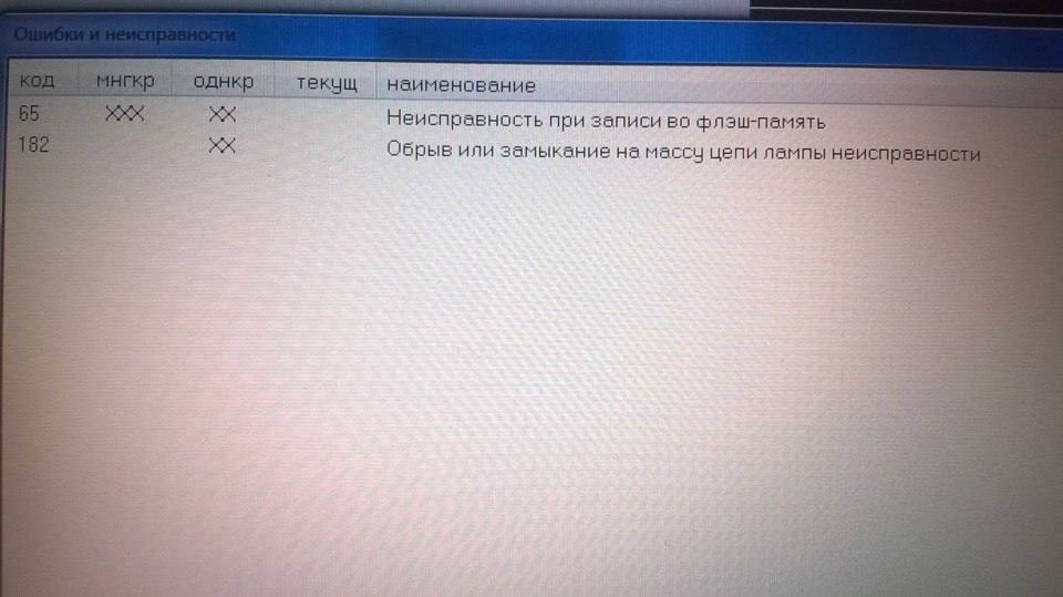
Ну вот опять беда пичаль, была как то раз запись про эту ошибку, но ничего я так и не нашел, катался и радовался, а сейчас научился прошивать, редактировать кои чо, ну и так по мелочи балуюсь с ЭБУ. И сидит занозой эта ошибка, как в мозгу волги так теперь и у меня. Чует мое сердце что и не заводится она по утрам на холодную именно из-за неё, т.к. опыт показал следующее: прошил ЭБУ, поставил, завел, на холодную при температуре на улице -8 завелась как надо, обороты 1500 и не глохнет. Покатался немного, постояла остыла и без педали газа не заводится никак, 2 цилиндра подхватывают, а то и вовсе один. Снял ЭБУ, отключил, положил рядом на сиденье, через 3 часа подключил все обратно, и вуаля, опять сама завелась! Манипуляции с выставлением в прошивке угла зажигания при пуске, количестве искр и времени заряда катушки никакого результата не дают. И вот давеча наткнулся на статью, там сказано:
«Вероятно неисправна аппаратная часть (флэш-ОЗУ) блока управления двигателем.
1. Отсоедините блок управления от жгута проводов и внимательно осмотрите целостность контактов розетки жгута и вилки блока. При необходимости отрихтуйте контакты соединителя или замените их. При обнаружении воды в соединителе блок необходимо снять, остатки воды удалить, просушить блок при температуре не выше 85°C.
2. Подключите к системе контрольный блок управления.
3. После замены тестируемого блока на контрольный включите зажигание, запустите двигатель и проконтролируйте отсутствие кода неисправности «065».» Ссылка на полную статью: autodst.ru/diagnostikagaz…hibok-gaz/86-kod-065.html
Перепрошивка не помогает, такое впечатление что двигатель работает на аварийной программе. И хрена его знает чо теперь делать!
Ваз 2110 2002г. Январь 5.1 Ошибка EEPROM — ChipTuner Forum
![]()
Чип-тюнинг коммерческой техники Кама3, ГАЗ от SMS-Soft
| Прошивки Hyundai SIM2K от Strit | Прошивки Magneti Marelli VAG от Art-Pro | Прошивки Peugeot/Citroen от Art-Pro | Прошивки Kia SIM2K-241 от Strit |
Ваз 2110 2002г. Январь 5.1 Ошибка EEPROM
-
Закрытая тема.
-

offline
ИПГ
- Регистрация:
- 03.01.2009
- Сообщений:
- 2,452
- Адрес:
- Архангельск
Сегодня делал машинку и столкнулся с данной ошибкой.
При попытке изменения RKOD (коррекция СО) , параметр записывается ,но в ошибках вылезает «Ошибка EEPROM»
Параметр сохраняется только до выключения зажигания. После вкл. выставляется в 0.
И есть проблема в движении. Поездив 10 минут машина начинает тупить и подтраивать.
При перевключении зажигания проблема пропадает на такой же срок.
Свечи,возд.фильтр новые, провода проверены (Мотор-тестером).
Давл топл.-норм.(2,8-3,4) Компрессия одинаковая около 12 кг.
АЦП ДМРВ при вкл. зажигании -0,996
ДПЗ исправен.
Ошибок при экслуатации нет.
Не проверены форсунки.
Предохранители целые.
СО х.х — 4,4
СН -180
СО2- 15,4
При корректировке -СО можно загнать в нормы.(но только до выкл. заж.)
Вопрос.
1. Думаю перепрошить- но в связи с этой ошибкой можно ли «потерять» блок?
2. В связи с чем может появится данная ошибка? -

offline
Автодиагност
- Регистрация:
- 21.02.2006
- Сообщений:
- 13,561
- Адрес:
- Липецкая обл. г.Елец
Либо EEPROM неисправна, либо до Вас авто криво прошили (что скорее всего)
-

offline
Диагностика, Чиптюнинг.
- Регистрация:
- 19.11.2006
- Сообщений:
- 11,242
- Адрес:
- Майкоп или Кот 01
Полный индефикатор ЕБУ и ПО в студию.
-
offline
Автодиагност
- Регистрация:
- 21.02.2006
- Сообщений:
- 13,561
- Адрес:
- Липецкая обл. г.Елец
-
offline
ИПГ
- Регистрация:
- 03.01.2009
- Сообщений:
- 2,452
- Адрес:
- Архангельск
ЭБУ 2111-1411020-71 J5V13I02
Кс не считывал. -
offline
Автодиагност
- Регистрация:
- 21.02.2006
- Сообщений:
- 13,561
- Адрес:
- Липецкая обл. г.Елец
B4CE должна быть , пробовать перешить для начала
-
offline
Диагностика, Чиптюнинг.
- Регистрация:
- 19.11.2006
- Сообщений:
- 11,242
- Адрес:
- Майкоп или Кот 01
По буквачкам похоже на правельную, тогда вопрос, чем смотриш?
Ваще попробуй перезаписать с сайта ( или попалам, или в дребезги ). -

offline
Диагностика, чиптюнинг, ТО
- Регистрация:
- 12.02.2007
- Сообщений:
- 12,668
- Адрес:
- Миллерово Ростовской обл
знаем мы эти букавки, на заборе тоже написанно…., сливать и сравнивать
-
offline
ИПГ
- Регистрация:
- 03.01.2009
- Сообщений:
- 2,452
- Адрес:
- Архангельск
Так и спрашиваю Блок то не сдохнет ? Подмены просто нет.
Смотрел kwp new -
offline
ИПГ
- Регистрация:
- 03.01.2009
- Сообщений:
- 2,452
- Адрес:
- Архангельск
-
offline
ИПГ
- Регистрация:
- 03.01.2009
- Сообщений:
- 2,452
- Адрес:
- Архангельск
Дерганье было из за забитого топл. фильтра с сетки на насосе.
По СО все так и осталось. И с ошибкой тоже.
Клиент побоялся мозги шить. Так уехал.
-
Закрытая тема.
Коды ошибок промышленных кондиционеров LG.
Внутренний блок:
01 – датчик температуры воздуха короткозамкнут или обрыв в цепи;
02 – датчик температуры испарителя короткозамкнут или обрыв в цепи;
03 – плохое соединение внутреннего блока с проводным пультом управления;
04 – ошибка дренажного насоса (помпы) или поплавкового датчика уровня конденсата;
05 – ошибка в межблочном соединении внешнего и внутреннего блоков;
06 – датчик температуры наружного блока короткозамкнут или обрыв в цепи;
07 – внутренние блоки мультиситсемы включены на разные режимы работы;
HL – та же ошибка, что и 04, поплавковый датчик разомкнут;
CL – установлен детский замок, для включения нажмите Timer & Min Buttons 3 секунды;
Po – установлен режим jet cool, для выхода нажмите кнопку jet cool
Внешний блок:
21 – перегрузка компрессора по току;
22 – ток компрессора более 14 А;
23 – напряжение постоянного тока ниже 140 В; (не напряжение питания, а после модуля преобразования)
24 – ошибка по высокому/низкому давлению, датчики давления разомкнуты;
25 – напряжение питания выше/ниже нормального значения;
26 – DC Compressor Position;
27 – ошибка PSC (реактор, катушка индуктивности);
28 – DC Link High Volts;
32 – Высокая температура нагнетательной трубы (INV);
33 – Высокая температура нагнетательной трубы (Cons.);
40 – короткое замыкание CT;
41 – датчик температуры D-Pipe замкнут/оборван (INV);
44 – датчик температуры наружного воздуха замкнут/оборван;
45 – датчик температуры конденсатора замкнут/оборван;
46 – датчик на всасывающей трубке замкнут/оборван;
47 – D-pipe датчик замкнут/оборван;
48 – D-pipe датчик и датчик температуры воздуха отсутствуют/оборваны;
51 – комбинированная перегрузка по мощности;
52 – ошибка соединения (main micom-sub micom);
53 – ошибка соединения (внутренний-наружный блоки);
54 – для систем с 3-хфазным питанием, неправильная последовательность фаз,поменять фазу;
60 -ошибка EEPROM (внутренняя энергонезависимая память)
61 -высокая температура трубки конденсатора (конденсера)
62 -высокая температура радиатора(скорее всего имеется в виду радиатор охлаждения силового модуля инвертора)
63 -низкая температура конденсатора
65 -датчик температуры радиатора замкнут/оборван
67 -заблокирован наружный BLDC (безколлекторный электродвигатель постоянного тока) вентилятор
105 -нет связи между главной платой управления и платой управления вентилятором
Коды ошибок всех настенных кондиционеров LG, в том числе серии Art Cool
C1 или CH1 – внутренний датчик температуры воздуха короткозамкнут или обрыв в цепи;
C2 или CH2 – датчик температуры испарителя короткозамкнут или обрыв в цепи;
C4 или CH4 – температурный датчик конденсатора короткозамкнут или обрыв в цепи;
C5 или CH5 – соединение между внешним и внутренним блоками;
C6 или CH6 – превышен ток в цепи инверторного модуля;
C7 или CH7 – превышен ток компрессора;
C8 или CH8 – не вращается вентилятор внутреннего блока;
C9 или CH9 – не вращается вентилятор внешнего блока;
C10 или CH-10 – неисправен терморезистор контроля температуры корпуса компрессора сплит системы (обрыв или короткое замыкание)
CA – температура нагнетания выше 130 0С;
CC – ошибка EEPROM (внутренняя энергонезависимая память);
CD – ошибка в инверторном модуле;
CE
Po – система находится в энергосберегающем режиме, ошибки нет;
Lo – система находится в режиме тестирования,ошибки нет;
Если кода ошибки нет,а моргают светодиодные индикаторы на панели необходимо скачать полную версию кода ошибок, там же находится график зависимости сопротивления температурного датчика от температуры.
Все коды ошибок кондиционеров LG
|
Код неисправности |
Расшифровка кода ошибки |
|
00 |
Text the 1, 2 or 3 digit fault code number only. I.e. If you see fault code CH07 on your indoor unit or R/Controller, only type 7 or 07 in your text message. |
|
01 |
Indoor unit return air sensor fault. Disconnect sensor from PCB and measure resistance. 8 kOhm at 30C and 13 kOhm at 20C if not replace sensor |
|
1 |
Indoor unit return air sensor fault. Disconnect sensor from PCB and measure resistance. 8 kOhm at 30C and 13 kOhm at 20C if not replace sensor |
|
02 |
Indoor Pipe Sensor or Outdoor Sensor Assy fault, Open or Short. Disconnect from PCB and measure resistance. Air sensor = 10 kOhm at 25C, Pipe sensor = 5 kOhm at 25C. If not replace sensor. |
|
2 |
Indoor Pipe Sensor or Outdoor Sensor Assy fault, Open or Short. Disconnect from PCB and measure resistance. Air sensor = 10 kOhm at 25C, Pipe sensor = 5 kOhm at 25C. If not replace sensor. |
|
03 |
Remote controller comms error. Check wired correctly, if so check dipswitch in RC. Set to Sg for 1 unit, or Gr for group then reset power |
|
3 |
Remote controller comms error. Check wired correctly, if so check dipswitch in RC. Set to Sg for 1 unit, or Gr for group then reset power |
|
04 |
RAC Product = Heat Sink Sensor Error, Open/Short Cct or over 95C. Commercial Product = Condensate pump float switch risen. Check drain pan is empty, check pump is working OK. If no pump check blue jumper plug is inserted in socket CN Float. |
|
4 |
RAC Product = Heat Sink Sensor Error, Open/Short Cct or over 95C. Commercial Product = Condensate pump float switch risen. Check drain pan is empty, check pump is working OK. If no pump check blue jumper plug is inserted in socket CN Float. |
|
05 |
Comms Error, check your wiring, remove external pumps. Split/Multi – check volts from terminal N to 3 = 0 – 65 Vdc, Multi V – 4 Vdc terminals 3 and 4 |
|
5 |
Comms Error, check your wiring, remove external pumps. Split/Multi – check volts from terminal N to 3 = 0 – 65 Vdc, Multi V – 4 Vdc terminals 3 and 4 |
|
06 |
Indoor unit coil sensor fault. Disconnect from PCB measure resistance. 10 kOhm at 10C and 4 kOhm at 30C. if not replace sensor. Split = text 21 |
|
6 |
Indoor unit coil sensor fault. Disconnect from PCB measure resistance. 10 kOhm at 10C and 4 kOhm at 30C. if not replace sensor. Split = text 21 |
|
07 |
Multi Splits and Multi V = indoor unit is set to run in a different mode from the master indoor unit. Set ALL indoor units to cooling or ALL to heating to clear. Splits = Compressor Over Current (CT2), also see Code 06. |
|
7 |
Multi Splits and Multi V = indoor unit is set to run in a different mode from the master indoor unit. Set ALL indoor units to cooling or ALL to heating to clear. Splits = Compressor Over Current (CT2), also see Code 06. |
|
RAC Indoor unit BLDC Fan problem. This is caused by the Indoor fan being locked. Check fan motor is plugged in correctly, Electrically & Mechanically sound. |
|
|
08 |
Check the fan motor turns freely, check the AC Voltage supplied to the fan motor, this will vary from 120 V ac at low speed to 170V AC at high speed. If no |
|
Voltage is present the the PCB is faulty, if Voltage is present the fan motor will be Faulty. |
|
|
RAC Indoor unit BLDC Fan problem. This is caused by the Indoor fan being locked. Check fan motor is plugged in correctly, Electrically & Mechanically sound. |
|
|
8 |
Check the fan motor turns freely, check the AC Voltage supplied to the fan motor, this will vary from 120 V ac at low speed to 170V AC at high speed. If no |
|
Voltage is present the the PCB is faulty, if Voltage is present the fan motor will be Faulty. |
|
|
09 |
Split = Outdoor unit fan problem. Check Outdoor fan motor is plugged in, Electrically & Mechanically sound, if not replace motor, otherwise replace PCB. Multi V = Indoor unit EEPROM error – Replace the indoor unit PCB, and then make sure to do Auto addressing and input the address of central control. |
|
9 |
Split = Outdoor unit fan problem. Check Outdoor fan motor is plugged in, Electrically & Mechanically sound, if not replace motor, otherwise replace PCB. Multi V = Indoor unit EEPROM error – Replace the indoor unit PCB, and then make sure to do Auto addressing and input the address of central control. |
|
10 |
RAC Product: Compressor discharge sensor fault. Disconnect from PCB measure resistance 237 kOhm at 20°C, 168 kOhm at 30C. Multi Fdx & Multi V text 8 |
|
11 |
Multi V indoor unit not connected to an outdoor unit. Check comms wiring is correct, and check initialisation has been carried out correctly |
|
12 |
RAC Product = EEPROM Sum Check Error, text 60 for help. |
|
13 |
RAC Product = PSC (Reactor) Error, text 27 for help. |
|
14 |
RAC Product = Compressor Phase Current Error |
|
15 |
no such fault code Text 1, 2 or 3 digit fault code number only. If you see fault code CH07 only type 7 in your text message |
|
16 |
no such fault code Text 1, 2 or 3 digit fault code number only. If you see fault code CH07 only type 7 in your text message |
|
17 |
no such fault code Text 1, 2 or 3 digit fault code number only. If you see fault code CH07 only type 7 in your text message |
|
18 |
no such fault code Text 1, 2 or 3 digit fault code number only. If you see fault code CH07 only type 7 in your text message |
|
19 |
no such fault code Text 1, 2 or 3 digit fault code number only. If you see fault code CH07 only type 7 in your text message |
|
20 |
no such fault code Text 1, 2 or 3 digit fault code number only. If you see fault code CH07 only type 7 in your text message |
|
21 |
Inverter compressor run current high. Check compressor windings all equal 1 to 4 Ohms, Check to earth 50 MOhm minimum, check run current |
|
22 |
Inverter compressor run current high. Check compressor windings all equal 1 to 4 Ohms . Check to earth 50 MOhm minimum, check run current |
|
23 |
Inverter dc voltage low. Check dc voltage of capacitors 300 Vdc for 1Ph and 600 Vdc for 3Ph. If OK change outdoor inverter PCB |
|
24 |
Splits and Multi Splits = High or low pressure trip. Low at 1 bar High at 35 bar check pressures. Multi V = High pressure trip. |
|
25 |
Check power supply voltage to the outdoor unit is correct (1ph ?220 Vac ±10% or 3ph ?380 Vac ±10%). If OK, check fuses, if fuses are OK replace outdoor main PCB |
|
26 |
Inverter compressor seized. Check compressor windings all equal resistance 1 to 4 Ohms, check to earth 50 MOhm minimum, check run current and Inverter outputs |
|
27 |
Inverter current irregularity. Check inverter PCB, check reactor connections and its resistance is less than 1 ohm. |
|
28 |
Inverter dc voltage too high. Check dc voltage of capacitors 300 Vdc for 1Ph and 600 Vdc for 3Ph. If OK change outdoor inverter PCB |
|
29 |
no such fault code Text 1, 2 or 3 digit fault code number only. If you see fault code CH07 only type 7 in your text message |
|
30 |
no such fault code Text 1, 2 or 3 digit fault code number only. If you see fault code CH07 only type 7 in your text message |
|
31 |
no such fault code Text 1, 2 or 3 digit fault code number only. If you see fault code CH07 only type 7 in your text message |
|
32 |
Inverter compressor discharge temperature too high. If over 105°C, check refrigerant charge |
|
33 |
Excessive rise of standard compressor discharge temperature. If over 105°C check refrigerant charge |
|
34 |
Excessive high pressure rise, over 35 bar at HP sensor. Check pressures, check coils, and filters are clean check for OFN in system pipework |
|
35 |
Excessive low pressure drop under 1 Bar at LP sensor. Check pressures, and check service valves open |
|
36 |
no such fault code Text 1, 2 or 3 digit fault code number only. If you see fault code CH07 only type 7 in your text message |
|
37 |
no such fault code Text 1, 2 or 3 digit fault code number only. If you see fault code CH07 only type 7 in your text message |
|
38 |
no such fault code Text 1, 2 or 3 digit fault code number only. If you see fault code CH07 only type 7 in your text message |
|
39 |
no such fault code Text 1, 2 or 3 digit fault code number only. If you see fault code CH07 only type 7 in your text message |
|
40 |
Inverter ac current abnormal. Check compressor windings all equal resistance 1 to 4 Ohms, check to earth 50 MOhm minimum, check run current and inverter outputs |
|
41 |
Inverter compressor discharge sensor fault. Disconnect from PCB measure resistance 237 kOhm at 20°C and 168 kOhm at 30°C. |
|
42 |
Low pressure sensor fault. Check dc voltage between white and black cable on plug. Multi V: 1 Vdc = 4 bar up to 5 Vdc = 32 bar |
|
43 |
High pressure sensor fault. Check dc voltage between white and black cable on plug. Multi V: 1 Vdc = 8 bar up to 2.5 Vdc = 37 bar |
|
44 |
Outdoor unit air sensor fault. Disconnect from PCB and measure resistance. 8 kOhm at 30C and 13 kOhm at 20C. If OK replace PCB, if not replace sensor |
|
45 |
Outdoor unit coil sensor fault. Disconnect from PCB measure resistance. 10 kOhm at 10°C and 4 kOhm at 30°C. If OK replace PCB, if not replace sensor |
|
46 |
Outdoor unit suction sensor fault. Disconnect from PCB and measure resistance. 10 kOhm at 10°C and 4 kOhm at 30°C. If OK replace PCB, if not replace sensor |
|
47 |
Compressor discharge sensor fault. Disconnect from PCB measure resistance. 237 kOhm at 20°C and 168 kOhm at 30°C. If OK replace PCB, if not replace sensor |
|
48 |
Split/Multi Split = Outdoor unit discharge and air sensor both unplugged. Multi V = Outdoor unit coil sensor. Text 45 for diagnostics |
|
49 |
Check power supply voltage to the outdoor unit is correct (1ph ?220 Vac ±10% or 3ph ?380 Vac ±10%). If OK check fuses, if fuses OK, replace outdoor main PCB |
|
50 |
no such fault code Text 1, 2 or 3 digit fault code number only. If you see fault code CH07 only type 7 in your text message |
|
51 |
Unit mismatch. Check model number of units do not exceed maximum. Multi V – also check Sub outdoor unit dipswitch settings |
|
52 |
Communication error between inverter PCB and main outdoor unit PCB. Check wiring fuses and LEDs . If OK either inverter or main PCB defective |
|
53 |
Comms error indoor to outdoor unit. Check your wiring . Split and Multi – check voltage from terminal N to 3 = 0 – 65 Vdc, Multi V – 4 Vdc terminals 3 and 4 |
|
54 |
Reverse or open phase. Check all 3 phases are present and correct. If correct voltage appears at all three phases, swap any two to cure the fault |
|
55 |
no such fault code Text 1, 2 or 3 digit fault code number only. If you see fault code CH07 only type 7 in your text message |
|
56 |
no such fault code Text 1, 2 or 3 digit fault code number only. If you see fault code CH07 only type 7 in your text message |
|
57 |
Comms error between outdoor main PCB and inverter PCB. Check wiring fuses and LEDs are lit. If OK either inverter or main PCB defective |
|
58 |
no such fault code Text 1, 2 or 3 digit fault code number only. If you see fault code CH07 only type 7 in your text message |
|
59 |
no such fault code Text 1, 2 or 3 digit fault code number only. If you see fault code CH07 only type 7 in your text message |
|
60 |
Outdoor unit PCB EEPROM failure, try removing EEPROM and refitting if removable (possible contact fault), otherwise replace PCB if the EEPROM is non-removable. |
|
61 |
Condenser coil over 65°C. Check coil and filters are clean and free from debris, and airflow is OK. Check system pressures for non-condesables |
|
62 |
Inverter over 85°C. Check air flow across heat sink, check inverter tight to heatsink use thermal paste. Multi V – check inverter cooling fan |
|
63 |
Multi F(DX) – “Cond. Pipe Sensor Temp. Low” (opposite to Error Code 61). Check Temperature/Resistance reading and replace sensor if found to be faulty. If sensor okay, check for cause of low temperature and rectify. |
|
64 |
no such fault code Text 1, 2 or 3 digit fault code number only. If you see fault code CH07 only type 7 in your text message |
|
65 |
Outdoor unit inverter fin temperature sensor fault. Disconnect from PCB measure resistance. 8 kOhm at 30°C and 13 kOhm at 20°C |
|
67 |
Outdoor Fan Motor siezed, or rotation sensing circuit failure. Check motor for mechanical and/or electrical failure, if okay replace pcb. |
|
100 |
Excessive discharge temperature rise 105°C Sub condenser 1 standard compressor. Check refrigerant |
|
101 |
Excessive discharge temperature rise 105°C Sub condenser 1 standard compressor. Check refrigerant |
|
102 |
Excessive discharge temperature rise 105°C Sub condenser 2 standard compressor. Check refrigerant |
|
103 |
Excessive discharge temperature rise 105°C Sub condenser 2 standard compressor. Check refrigerant |
|
104 |
Communication error between Main and Sub outdoor units. Check comms wiring and power to all outdoor units |
|
105 |
Communication error between outdoor main PCB and fan PCB. Check plug connections and LEDs. If OK, replace either main or fan PCB |
|
106 |
Outdoor unit fan motor high current. Check fans rotate freely, and are connected correctly |
|
107 |
Outdoor unit low voltage to fan PCB. Check 300 Vdc supply, check fuses and plug connections. If OK, replace fan PCB |
|
108 |
Communication error between outdoor main PCB, and fan PCB. Check plug connections and LEDs. If OK replace either main or fan PCB |
|
109 |
Sub 1 excessive rise of high pressure. Check pressures, check for non condensables, check heat exchanger coil is free from debris |
|
110 |
Sub 1 reverse or open phase. Check all 3 phases are present and correct. If correct voltage appears at all three phases, swap any two to cure the fault |
|
111 |
Communication error between Main and Sub outdoor units. Check comms wiring and power to all outdoor units |
|
113 |
Main outdoor unit liquid pipe sensor fault. Disconnect from PCB and measure resistance. 10 kOhm at 10°C and 4 kOhm at 30°C |
|
114 |
Main outdoor unit Subcool inlet sensor fault. Disconnect from PCB and measure resistance. 10 kOhm at 10°C and 4 kOhm at 30°C |
|
115 |
Main outdoor unit Subcool outlet sensor fault. Disconnect from PCB and measure resistance. 10 kOhm at 10°C and 4 kOhm at 30°C |
|
116 |
Sub 1 high pressure sensor fault. Check dc voltage between white and black cable on plug. Multi V: 1 Vdc = 8 bar up to 2.5 Vdc = 37 bar |
|
117 |
Sub 1 low pressure sensor fault. Check dc voltage between white and black cable on plug. Multi V: 1 Vdc = 4 bar up to 5 Vdc = 32 bar |
|
118 |
Sub 1 outdoor unit air sensor fault. Disconnect from PCB and measure resistance. 8 kOhm at 30°C and 13 kOhm at 20°C. If OK replace PCB, if not replace sensor |
|
120 |
Sub 1 outdoor unit suction sensor fault. Disconnect from PCB and measure resistance. 10 kOhm at 10°C and 4 kOhm at 30°C. if not replace sensor |
|
121 |
Sub 1 compressor 1 discharge sensor fault. Disconnect from PCB measure resistance 237 kOhm at 20°C and 168 kOhm at 30°C. if not replace sensor |
|
122 |
Sub 1 compressor 2 discharge sensor fault. Disconnect from PCB measure resistance 237 kOhm at 20°C and 168 kOhm at 30°C. if not replace sensor |
|
123 |
Sub 1 outdoor unit coil sensor A fault. Disconnect from PCB measure resistance. 10 kOhm at 10°C and 4 kOhm at 30°C. If OK replace PCB, if not replace sensor |
|
124 |
Sub 1 outdoor unit coil sensor B fault. Disconnect from PCB measure resistance. 10 kOhm at 10°C and 4 kOhm at 30°C. If OK replace PCB, if not replace sensor |
|
125 |
Sub 1 outdoor unit liquid pipe sensor fault. Disconnect from PCB and measure resistance. 10 kOhm at 10°C and 4 kOhm at 30°C |
|
126 |
Sub 1 outdoor unit Subcool inlet sensor fault. Disconnect from PCB and measure resistance. 10 kOhm at 10°C and 4 kOhm at 30°C |
|
127 |
Sub 1 outdoor unit Subcool outlet sensor fault. Disconnect from PCB and measure resistance. 10 kOhm at 10°C and 4 kOhm at 30°C |
|
128 |
Sub 2 high pressure sensor fault. Check dc voltage between white and black cable on plug. Multi V: 1 Vdc = 8 bar up to 2.5 Vdc = 37 bar |
|
129 |
Sub 2 low pressure sensor fault. Check dc voltage between white and black cable on plug. Multi V: 1 Vdc = 4 bar up to 5 Vdc = 32 bar |
|
130 |
Sub 2 outdoor unit air sensor fault. Disconnect from PCB and measure resistance. 8 kOhm at 30°C and 13 kOhm at 20°C. If OK replace PCB, if not replace sensor |
|
132 |
Sub 2 outdoor unit suction sensor fault. Disconnect from PCB and measure resistance. 10 kOhm at 10°C and 4 kOhm at 30°C.if not replace sensor |
|
133 |
Sub 2 compressor 1 discharge sensor fault. Disconnect from PCB measure resistance 237 kOhm at 20°C and 168kOhm at 30°C. if not replace sensor |
|
134 |
Sub 2 compressor 2 discharge sensor fault. Disconnect from PCB measure resistance 237 kOhm at 20°C and 168kOhm at 30°C.if not replace sensor |
|
135 |
Sub 2 outdoor unit coil sensor A fault. Disconnect from PCB measure resistance. 10 kOhm at 10°C and 4 kOhm at 30°C. If OK replace PCB, if not replace sensor |
|
136 |
Sub 2 outdoor unit coil sensor B fault. Disconnect from PCB measure resistance. 10 kOhm at 10°C and 4 kOhm at 30°C. If OK replace PCB, if not replace sensor |
|
137 |
Sub 2 outdoor unit liquid pipe sensor fault. Disconnect from PCB and measure resistance. 10 kOhm at 10°C and 4 kOhm at 30°C |
|
138 |
Sub 2 outdoor unit Subcool inlet sensor fault. Disconnect from PCB and measure resistance. 10 kOhm at 10°C and 4 kOhm at 30°C |
|
139 |
Sub 2 outdoor unit Subcool outlet sensor fault. Disconnect from PCB and measure resistance. 10 kOhm at 10°C and 4 kOhm at 30°C |
|
140 |
Sub 2 excessive rise of high pressure. Check pressures, check for non condensables, check heat exchanger coil is free from debris |
|
141 |
Sub 2 reverse or open phase. Check all 3 phases are present and correct. If correct voltage appears at all three phases, swap any two to cure the fault |
|
142 |
Communication error between Main and Sub outdoor units. Check comms wiring and power to all outdoor units |
|
143 |
Sub 1 excessive rise of high pressure. Check pressures, check for non condensables, check heat exchanger coil is free from debris |
|
144 |
Sub 1 excessive drop of low pressure. Check pressures, check for non condensables, check heat exchanger coil is free from debris |
|
145 |
Sub 2 excessive rise of high pressure. Check pressures, check for non condensables, check heat exchanger coil is free from debris |
|
146 |
Sub 2 excessive drop of low pressure. Check pressures, check for non condensables, check heat exchanger coil is free from debris |
|
147 |
Sub 1 check power supply voltage to the outdoor unit is correct (1ph 220 Vac ±10% or 3ph 380 Vac ±10%).check fuses, if fuses OK replace outdoor main PCB |
|
148 |
Sub 1 check power supply voltage to the outdoor unit is correct (1ph 220 Vac ±10% or 3ph 380 Vac ±10%). check fuses, if fuses OK replace outdoor main PCB |
|
149 |
Sub 2 check power supply voltage to the outdoor unit is correct (1ph 220 Vac ±10% or 3ph 380 Vac ±10%). check fuses, if fuses OK replace outdoor main PCB |
|
150 |
Sub 2 check power supply voltage to the outdoor unit is correct (1ph 220 Vac ±10% or 3ph 380 Vac ±10%). check fuses, if fuses OK replace outdoor main PCB |
|
151 |
Faulty 4 way valve. Check solenoid coil and output from PCB. If OK, mechanical failure. |
|
152 |
Excessive discharge temperature rise 105°C Sub condenser 2 standard compressor. Check refrigerant |
|
153 |
Excessive discharge temperature rise 105°C Sub condenser 2 standard compressor. Check refrigerant |
|
154 |
Sub 3 excessive rise of high pressure. Check pressures, check for non condensables, check heat exchanger coil is free from debris |
|
155 |
Sub 3 reverse or open phase. Check all 3 phases are present and correct. If correct voltage appears at all three phases, swap any two to cure the fault |
|
156 |
Communication error between Main and Sub outdoor units. Check comms wiring and power to all outdoor units |
|
157 |
Sub 3 high pressure sensor fault. Check dc voltage between white and black cable on plug. Multi V: 1 Vdc = 8 bar up to 2.5 Vdc = 37 bar |
|
158 |
Sub 3 low pressure sensor fault. Check dc voltage between white and black cable on plug. Multi V: 1 Vdc = 4 bar up to 5 Vdc = 32 bar |
|
159 |
Sub 3 outdoor unit air sensor fault. Disconnect from PCB and measure resistance. 8 kOhm at 30°C and 13 kOhm at 20°C. If OK replace PCB, if not replace sensor |
|
161 |
Sub 3 outdoor unit suction sensor fault. Disconnect from PCB and measure resistance. 10 kOhm at 10°C and 4 kOhm at 30°C. if not replace sensor |
|
162 |
Sub 3 compressor 1 discharge sensor fault. Disconnect from PCB measure resistance 237 kOhm at 20°C and 168 kOhm at 30°C. if not replace sensor |
|
163 |
Sub 3 compressor 2 discharge sensor fault. Disconnect from PCB measure resistance 237 kOhm at 20°C and 168 kOhm at 30°C.if not replace sensor |
|
164 |
Sub 3 outdoor unit coil sensor A fault. Disconnect from PCB measure resistance. 10 kOhm at 10°C and 4 kOhm at 30°C. If OK replace PCB, if not replace sensor |
|
165 |
Sub 3 outdoor unit coil sensor B fault. Disconnect from PCB measure resistance. 10 kOhm at 10°C and 4 kOhm at 30°C. If OK replace PCB, if not replace sensor |
|
166 |
Sub 3 outdoor unit liquid pipe sensor fault. Disconnect from PCB and measure resistance. 10 kOhm at 10°C and 4 kOhm at 30°C |
|
167 |
Sub 3 outdoor unit Subcool inlet sensor fault. Disconnect from PCB and measure resistance. 10 kOhm at 10°C and 4 kOhm at 30°C |
|
168 |
Sub 3 outdoor unit Subcool outlet sensor fault. Disconnect from PCB and measure resistance. 10 kOhm at 10°C and 4 kOhm at 30°C |
|
169 |
Sub 3 excessive rise of high pressure. Check pressures, check for non condensables, check heat exchanger coil is free from debris |
|
170 |
Sub 3 excessive drop of low pressure. Check pressures, check for non condensables, check heat exchanger coil is free from debris |
|
171 |
Sub 3 check power supply voltage to the outdoor unit is correct (1ph 220 Vac ±10% or 3ph 380 Vac ±10%). check fuses, if fuses OK replace outdoor main PCB |
|
172 |
Sub 3 check power supply voltage to the outdoor unit is correct (1ph 220 Vac ±10% or 3ph 380 Vac ±10%). check fuses, if fuses OK replace outdoor main PCB |
|
173 |
Main outdoor unit standard compressor not starting. Check output from main PCB, check contactor, and check wiring connections. If OK compressor faulty |
|
174 |
Sub 1 standard compressor 1 not starting. Check output from main PCB, check contactor, and check wiring connections. If OK compressor faulty |
|
175 |
Sub 1 standard compressor 2 not starting. Check output from main PCB, check contactor, and check wiring connections. If OK compressor faulty |
|
176 |
Sub 2 standard compressor 1 not starting. Check output from main PCB, check contactor, and check wiring connections. If OK compressor faulty |
|
177 |
Sub 2 standard compressor 2 not starting. Check output from main PCB, check contactor, and check wiring connections. If OK compressor faulty |
|
204 |
Comms Error between Outdoor Unit and HR Box No1. 1. Defective connection in HR unit power supply and transmission connection 2. Wrong setting of the HR unit Rotary switch and Dip switch 3. Defective HR unit PCB |
|
208 |
Comms Error between Outdoor Unit and HR Box No2. 1. Defective connection in HR unit power supply and transmission connection 2. Wrong setting of the HR unit Rotary switch and Dip switch 3. Defective HR unit PCB |
|
212 |
Comms Error between Outdoor Unit and HR Box No3. 1. Defective connection in HR unit power supply and transmission connection 2. Wrong setting of the HR unit Rotary switch and Dip switch 3. Defective HR unit PCB |
|
240 |
Central controller wiring error. Check all comms wiring, including between controller and CNU, and IP addresses. If OK possible defective CNU |
|
241 |
Central controller data sending error. Either defective CNU or Central controller initialisation failure |
|
242 |
Central controller data receiving error. Either defective CNU or Central controller initialisation failure |
|
243 |
Central controller. Comms cable too long or picking up external electrical noise. If OK, mismatching of controllers, or defective CNU |
|
244 |
Central controller data receiving time out. Either defective CNU or Central controller initialisation failure |
|
245 |
Central controller data sending time out. Either defective CNU or Central controller initialisation failure |
|
246 |
Central controller data receiving time out. Either defective CNU or Central controller initialisation failure |
|
250 |
Central controller data receiving error. Either comms cable picking up external electrical noise, or defective CNU |
|
251 |
Central controller receiving no data. Either comms cable picking up external electrical noise, or defective CNU |
|
252 |
Central controller incorrect address error. Check addresses match, if OK either comms cable picking up external electrical noise, or defective CNU |
|
253 |
Central Controller Disconnection Error, No response from Air Conditioner. Check wiring, if OK either comms cable picking up external electrical noise, defective CNU, or Interface. |
|
C1 |
Indoor unit return air sensor fault, Open or Short. Disconnect sensor from PCB and measure resistance. 8 kOhm at 30C and 13 kOhm at 20C if not replace sensor |
|
C2 |
Indoor Pipe Sensor or Outdoor Sensor Assy fault, Open or Short. Disconnect from PCB and measure resistance. Air sensor = 10 kOhm at 25C, Pipe sensor = 5 kOhm at 25C. If not replace sensor. |
|
C4 |
RAC Product = Heat Sink Sensor Error, Open/Short Cct or over 95C. Commercial Product = Condensate pump float switch risen. Check drain pan is empty, check pump is working OK. If no pump check blue jumper plug is inserted in socket CN Float. |
|
C5 |
Comms Error, check your wiring, remove external pumps. Split/Multi – check volts from terminal N to 3 = 0 – 65 Vdc, Multi V – 4 Vdc terminals 3 and 4 |
|
C6 |
Inverter compressor run current high. Check compressor windings all equal 1 to 4 Ohms, Check to earth 50 MOhm minimum, check run current |
|
C7 |
Splits = Compressor Over Current (CT2), also see Code 06. |
|
RAC Indoor unit BLDC Fan problem. This is caused by the Indoor fan being locked. Check fan motor is plugged in correctly, Electrically & Mechanically sound. |
|
|
C8 |
Check the fan motor turns freely, check the AC Voltage supplied to the fan motor, this will vary from 120 V ac at low speed to 170V AC at high speed. If no |
|
Voltage is present the the PCB is faulty, if Voltage is present the fan motor will be Faulty. |
|
|
C9 |
Outdoor unit fan problem. Check Outdoor fan motor is plugged in, Electrically & Mechanically sound, if not replace motor, otherwise replace PCB. |
|
CA |
Compressor discharge sensor fault. Disconnect from PCB measure resistance 237 kOhm at 20°C, 168 kOhm at 30C. |
|
CC |
RAC Product = EEPROM Sum Check Error, text 60 for help. |
|
Cd |
RAC Product = PSC (Reactor) Error, text 27 for help. |
|
CE |
RAC Product = Compressor Phase Current Error |
|
CH00 |
Text the 1, 2 or 3 digit fault code number only. I.e. If you see fault code CH07 on your indoor unit or R/Controller, only type 7 or 07 in your text message. |
|
CH01 |
Indoor unit return air sensor fault. Disconnect sensor from PCB and measure resistance. 8 kOhm at 30C and 13 kOhm at 20C if not replace sensor |
|
CH02 |
Indoor Pipe Sensor or Outdoor Sensor Assy fault, Open or Short. Disconnect from PCB and measure resistance. Air sensor = 10 kOhm at 25C, Pipe sensor = 5 kOhm at 25C. If not replace sensor. |
|
CH03 |
Remote controller comms error. Check wired correctly, if so check dipswitch in RC. Set to Sg for 1 unit, or Gr for group then reset power |
|
CH04 |
RAC Product = Heat Sink Sensor Error, Open/Short Cct or over 95C. Commercial Product = Condensate pump float switch risen. Check drain pan is empty, check pump is working OK. If no pump check blue jumper plug is inserted in socket CN Float. |
|
CH05 |
Comms Error, check your wiring, remove external pumps. Split/Multi – check volts from terminal N to 3 = 0 – 65 Vdc, Multi V – 4 Vdc terminals 3 and 4 |
|
CH06 |
Indoor unit coil sensor fault. Disconnect from PCB measure resistance. 10 kOhm at 10C and 4 kOhm at 30C. if not replace sensor. Split = text 21 |
|
CH07 |
Multi Splits and Multi V = indoor unit is set to run in a different mode from the master indoor unit. Set ALL indoor units to cooling or ALL to heating to clear. Splits = Compressor Over Current (CT2), also see Code 06. |
|
RAC Indoor unit BLDC Fan problem. This is caused by the Indoor fan being locked. Check fan motor is plugged in correctly, Electrically & Mechanically sound. |
|
|
CH08 |
Check the fan motor turns freely, check the AC Voltage supplied to the fan motor, this will vary from 120 V ac at low speed to 170V AC at high speed. If no |
|
Voltage is present the the PCB is faulty, if Voltage is present the fan motor will be Faulty. |
|
|
CH09 |
Split = Outdoor unit fan problem. Check Outdoor fan motor is plugged in, Electrically & Mechanically sound, if not replace motor, otherwise replace PCB. Multi V = indoor PCB failure. Replace PCB |
|
CH10 |
RAC Product: Compressor discharge sensor fault. Disconnect from PCB measure resistance 237 kOhm at 20°C, 168 kOhm at 30C. Multi Fdx & Multi V text 8 |
|
CH11 |
Multi V indoor unit not connected to an outdoor unit. Check comms wiring is correct, and check initialisation has been carried out correctly |
|
CH12 |
no such fault code Text 1, 2 or 3 digit fault code number only. If you see fault code CH07 only type 7 in your text message |
|
CH13 |
no such fault code Text 1, 2 or 3 digit fault code number only. If you see fault code CH07 only type 7 in your text message |
|
CH14 |
no such fault code Text 1, 2 or 3 digit fault code number only. If you see fault code CH07 only type 7 in your text message |
|
CH15 |
no such fault code Text 1, 2 or 3 digit fault code number only. If you see fault code CH07 only type 7 in your text message |
|
CH16 |
no such fault code Text 1, 2 or 3 digit fault code number only. If you see fault code CH07 only type 7 in your text message |
|
CH17 |
no such fault code Text 1, 2 or 3 digit fault code number only. If you see fault code CH07 only type 7 in your text message |
|
CH18 |
no such fault code Text 1, 2 or 3 digit fault code number only. If you see fault code CH07 only type 7 in your text message |
|
CH19 |
no such fault code Text 1, 2 or 3 digit fault code number only. If you see fault code CH07 only type 7 in your text message |
|
CH20 |
no such fault code Text 1, 2 or 3 digit fault code number only. If you see fault code CH07 only type 7 in your text message |
|
CH21 |
Inverter compressor run current high. Check compressor windings all equal 1 to 4 OhmsCheck to earth 50 MOhm minimum, check run current |
|
CH22 |
Inverter compressor run current high. Check compressor windings all equal 1 to 4 Ohms . Check to earth 50 MOhm minimum, check run current |
|
CH23 |
Inverter dc voltage low. Check dc voltage of capacitors 300 Vdc for 1Ph and 600 Vdc for 3Ph. If OK change outdoor inverter PCB |
|
CH24 |
Splits and Multi Splits = High or low pressure trip. Low at 1 bar High at 35 bar check pressures. Multi V = High pressure trip. |
|
CH25 |
Check power supply voltage to the outdoor unit is correct (1ph ?220 Vac ±10% or 3ph ?380 Vac ±10%). If OK, check fuses, if fuses are OK replace outdoor main PCB |
|
CH26 |
Inverter compressor seized. Check compressor windings all equal resistance 1 to 4 Ohms, check to earth 50 MOhm minimum, check run current and Inverter outputs |
|
CH27 |
Inverter current irregularity. Check inverter PCB and reactor |
|
CH28 |
Inverter dc voltage too high. Check dc voltage of capacitors 300 Vdc for 1Ph and 600 Vdc for 3Ph. If OK change outdoor inverter PCB |
|
CH29 |
no such fault code Text 1, 2 or 3 digit fault code number only. If you see fault code CH07 only type 7 in your text message |
|
CH30 |
no such fault code Text 1, 2 or 3 digit fault code number only. If you see fault code CH07 only type 7 in your text message |
|
CH31 |
no such fault code Text 1, 2 or 3 digit fault code number only. If you see fault code CH07 only type 7 in your text message |
|
CH32 |
Inverter compressor discharge temperature too high. If over 105°C, check refrigerant charge |
|
CH33 |
Excessive rise of standard compressor discharge temperature. If over 105°C check refrigerant charge |
|
CH34 |
Excessive high pressure rise, over 35 bar at HP sensor. Check pressures, check coils, and filters are clean check for OFN in system pipework |
|
CH35 |
Excessive low pressure drop under 1 Bar at LP sensor. Check pressures, and check service valves open |
|
CH36 |
no such fault code Text 1, 2 or 3 digit fault code number only. If you see fault code CH07 only type 7 in your text message |
|
CH37 |
no such fault code Text 1, 2 or 3 digit fault code number only. If you see fault code CH07 only type 7 in your text message |
|
CH38 |
no such fault code Text 1, 2 or 3 digit fault code number only. If you see fault code CH07 only type 7 in your text message |
|
CH39 |
no such fault code Text 1, 2 or 3 digit fault code number only. If you see fault code CH07 only type 7 in your text message |
|
CH40 |
Inverter ac current abnormal. Check compressor windings all equal resistance 1 to 4 Ohms, check to earth 50 MOhm minimum, check run current and inverter outputs |
|
CH41 |
Inverter compressor discharge sensor fault. Disconnect from PCB measure resistance 237 kOhm at 20C and 168 kOhm at 30C. |
|
CH42 |
Low pressure sensor fault. Check dc voltage between white and black cable on plug. Multi V: 1 Vdc = 4 bar up to 5 Vdc = 32 bar |
|
CH43 |
High pressure sensor fault. Check dc voltage between white and black cable on plug. Multi V: 1 Vdc = 8 bar up to 2.5 Vdc = 37 bar |
|
CH44 |
Outdoor unit air sensor fault. Disconnect from PCB and measure resistance. 8 kOhm at 30°C and 13 kOhm at 20°C. If OK replace PCB, if not replace sensor |
|
CH45 |
Outdoor unit coil sensor fault. Disconnect from PCB measure resistance. 10 kOhm at 10°C and 4 kOhm at 30°C. If OK replace PCB, if not replace sensor |
|
CH46 |
Outdoor unit suction sensor fault. Disconnect from PCB and measure resistance. 10 kOhm at 10°C and 4 kOhm at 30°C. If OK replace PCB, if not replace sensor |
|
CH47 |
Compressor discharge sensor fault. Disconnect from PCB measure resistance. 237 kOhm at 20°C and 168 kOhm at 30°C. If OK replace PCB, if not replace sensor |
|
CH48 |
Split/Multi Split = Outdoor unit discharge and air sensor both unplugged. Multi V = Outdoor unit coil sensor. Text 45 for diagnostics |
|
CH49 |
Check power supply voltage to the outdoor unit is correct (1ph ?220 Vac ±10% or 3ph ?380 Vac ±10%). If OK check fuses, if fuses OK, replace outdoor main PCB |
|
CH50 |
no such fault code Text 1, 2 or 3 digit fault code number only. If you see fault code CH07 only type 7 in your text message |
|
CH51 |
Unit mismatch. Check model number of units do not exceed maximum. Multi V – also check Sub outdoor unit dipswitch settings |
|
CH52 |
Communication error between inverter PCB and main outdoor unit PCB. Check wiring fuses and LEDs . If OK either inverter or main PCB defective |
|
CH53 |
Comms error indoor to outdoor unit. Check your wiring . Split and Multi – check voltage from terminal N to 3 = 0 – 65 Vdc, Multi V – 4 Vdc terminals 3 and 4 |
|
CH54 |
Reverse or open phase. Check all 3 phases are present and correct. If correct voltage appears at all three phases, swap any two to cure the fault |
|
CH55 |
no such fault code Text 1, 2 or 3 digit fault code number only. If you see fault code CH07 only type 7 in your text message |
|
CH56 |
no such fault code Text 1, 2 or 3 digit fault code number only. If you see fault code CH07 only type 7 in your text message |
|
CH57 |
Comms error between outdoor main PCB and inverter PCB. Check wiring fuses and LEDs are lit. If OK either inverter or main PCB defective |
|
CH58 |
no such fault code Text 1, 2 or 3 digit fault code number only. If you see fault code CH07 only type 7 in your text message |
|
CH59 |
no such fault code Text 1, 2 or 3 digit fault code number only. If you see fault code CH07 only type 7 in your text message |
|
CH60 |
Outdoor unit PCB EEPROM failure, try removing EEPROM and refitting if removable (possible contact fault), otherwise replace PCB if the EEPROM is non-removable. |
|
CH61 |
Condenser coil over 65°C. Check coil and filters are clean and free from debris, and airflow is OK. Check system pressures for non-condesables |
|
CH62 |
Inverter over 85°C. Check air flow across heat sink, check inverter tight to heatsink use thermal paste. Multi V – check inverter cooling fan |
|
CH63 |
no such fault code Text 1, 2 or 3 digit fault code number only. If you see fault code CH07 only type 7 in your text message |
|
CH64 |
no such fault code Text 1, 2 or 3 digit fault code number only. If you see fault code CH07 only type 7 in your text message |
|
CH65 |
Outdoor unit inverter fin temperature sensor fault. Disconnect from PCB measure resistance. 8 kOhm at 30°C and 13 kOhm at 20°C |
|
CH67 |
Outdoor Fan Motor siezed, or rotation sensing circuit failure. Check motor for mechanical and electrical failure. |
|
CL |
CL = Child Lock. Press Timer & Min buttons simultaneously for 5 seconds to engage/disengage function. |
|
help |
Text the 1, 2 or 3 digit fault code number only. I.e. If you see fault code CH07 on your indoor unit or R/Controller, only type 7 or 07 in your text message. |
|
HL |
Condensate pump float switch risen. Check drain pan is empty, check pump is working OK. If no pump check blue jumper plug is inserted in socket CN Float. Alternatively, Dry Contact Interface is in “OFF” condition. Check status and adjust as necessary. |
|
Po |
Po = Jet Cool Mode selected. To cancel press Jet Cool, Fan Speed or Set Temperature button. |
-
18.11.2012, 21:50
#1

Новичок
 Прошу помощи для GU-S24HRN1. Неисправность EEPROM.
всем привет. ситуация следующая…
установлены сплиты в июне этого года. нормально отпахали. у заказчика возникла необходимость переноса нб с удлинением трассы (с крыши на стену здания заднего двора, длина трассы около 15 метров). перенесли, заправили, еще зимник добавили sb004. через несколько дней позвонил заказчик, сообщил, что один блок не работает (2 блока переносили).
результаты осмотра:
— на внутрянке моргает лампа «авто»
— на плате наружнего индикатор красный — 5 миганий
— компрессор принудительно пускается
— пробовали сбрасывать питанием, внутрянка включается, на наружке, на плате горит индикатор на время задержки пуска нб, по прошествии нескольких минут, когда должен стартануть, начинает моргать индикатор на плате (5 раз), внутрянка останавливается.если варианты его оживить малой кровью ? отправлять по гарантии долго, т.к. от москвы очень далеко находимся (свердловская обл).
-
18.11.2012, 21:56
#2
Местный

Не стыковка двух плат(наружки и внутряка). плату менять
-
18.11.2012, 21:58
#3
Новичок
Спасибо. А что могло послужить этому ?
-
18.11.2012, 22:24
#4
Пользователь
 Сообщение от gala

не стыковка двух плат(наружки и внутряка). плату менять
а до этого тоды как работал?
могли при переносе фазы (если 3ф) попутать — было такое, черти нб переносили, а запустить не смогли… думали стрясли при переносе.
сняли другой такой-же (с менее важного места) , перенесли (а он весит эдак под 120) на нижнюю парковку (с 3-го этажа, без крана, весь фасад — стекло с положительным наклоном, т.е. верёвки исключены, лифта нет, одно хорошее — широкие лесничные марши…)забегая вперед, они его потом назад тащили:-d
поставили перепаяли, включили… тот же эфект.
короче там ркф стоит, компрессор защищает….*jokingly*
-
20.11.2012, 19:34
#5
Новичок
-
20.11.2012, 20:00
#6
Пользователь
А как на счёт приходящего-уходящего по межблочке? Какая логика управления НБ (ККР или микропоц)? Не попала ли какая насекомая или ещё кто? Датчики в блоке есть? Питание собственных нужд НБ в норме?
Вариантов масса… Если нет точного определения кода ошибки, нужен электрик-автоматчик.
-
21.11.2012, 13:13
#7
Мастер -ломастер

Меняйте плату внутреннего блока , скорее всего неисправность произошла в результате неправильного подключения межблочки (монтажники напутали ,после сделали как надо , да поздно).
-
21.11.2012, 19:37
#8
Новичок
Сообщение от Amir
Меняйте плату внутреннего блока , скорее всего неисправность произошла в результате неправильного подключения межблочки (монтажники напутали ,после сделали как надо , да поздно).
он отработал несколько дней
-
21.11.2012, 21:54
#9
Пользователь
А на мои вопросы ответы есть??? Или тема уже исчерпана???
-
21.11.2012, 21:59
#10
Мастер

Сообщение от sumiha8374
А на мои вопросы ответы есть??? Или тема уже исчерпана???
Не шуми , Шумиха , голова болит
")
-
21.11.2012, 22:28
#11
Пользователь
Читай правильно транскрибцию: Су Миха
А по поводу шума, я ж не к тебе обращался, мне интересно!
-
22.11.2012, 06:44
#12
Новичок
Сообщение от sumiha8374
А как на счёт приходящего-уходящего по межблочке? Какая логика управления НБ (ККР или микропоц)? Не попала ли какая насекомая или ещё кто? Датчики в блоке есть? Питание собственных нужд НБ в норме?
Вариантов масса… Если нет точного определения кода ошибки, нужен электрик-автоматчик.— что именно под вопросом «уходящего-приходящего» ?
— логику управления не знаю (не владею знаниями в електронике)
— насекомые, очень наврядли, на вид все внутренности почти новые, никаких следов не видно
— датчики есть в блоке, но по ним отдельные ошибки- проверять не стал
— питание 222-223 Вт (запитывается с НБ)
-
22.11.2012, 08:25
#13
Пользователь
Сообщение от Рамарио
логику управления не знаю (не владею знаниями в електронике)
— датчики есть в блоке, но по ним отдельные ошибки- проверять не сталИзвини брат, по моему вся тема впустую. Зови автоматчика, он разберётся….
-
22.11.2012, 08:59
#14
Новичок
Сообщение от sumiha8374
Извини брат, по моему вся тема впустую. Зови автоматчика, он разберётся….
Тяжело у нас с ними в городе. Платы гарантийные, тем более. Отправлю в сервис.
-
10.07.2017, 10:00
#15
Местный
Добрый день. Друзья нужна прошивка для GC 24 на плате выбито CE-KFR70GW11Y.D.1.1.1-1 V2,8, наклейка на релюшках и коробке в которой плата CE-KFR61GW11Y, наклейка на памяти 30356- её собственно и нужно. Помогите, своего блока нет, можно конечно к рабочему клиенту сгонять- выпаять память — сканировать -впаять, но согласится ли клиент…целая история.
-
10.07.2017, 10:02
#16
Местный
Да, симптомы на 24м- постоянное непрерывное мигание красного светодиода
-
10.07.2017, 14:48
#17
Люблю свое дело!…

Какого светодиода? Где? Модель кондея та же?
-
10.07.2017, 16:08
#18
Местный
Сообщение от AleksScrew
Какого светодиода? Где? Модель кондея та же?
Сорри, модель самого кондиционера Дженерал Климат GU-S24HR 2008 года
Похожие темы
-
прошу помощи
от евгений54 в разделе Indesit — вопросы НЕ мастеров
Ответов: 10
Последнее сообщение: 14.12.2019, 19:22
-
Ответов: 5
Последнее сообщение: 26.02.2017, 13:07
-
Ответов: 3
Последнее сообщение: 21.03.2015, 14:43
-
Ответов: 7
Последнее сообщение: 01.07.2014, 03:27
-
Ответов: 16
Последнее сообщение: 25.09.2011, 18:59
Социальные закладки
Социальные закладки
-

Google

Ваши права
- Вы не можете создавать новые темы
- Вы не можете отвечать в темах
- Вы не можете прикреплять вложения
- Вы не можете редактировать свои сообщения
- BB коды Вкл.
- Смайлы Вкл.
- [IMG] код Вкл.
- [VIDEO] код Вкл.
- HTML код Выкл.
Правила форума
-

Alex48
- Сообщения: 198
- Зарегистрирован: Вс июн 10, 2012 1:57 pm
- Откуда: Липецк
EDC MS 5 ошибка EEPROM
Всем привет, на MANе 23.414 во время стирания ошибок, водитель попытался завести машину в итоге вылезла ошибка 32 — ошибка EEPROM1
Как она лечится? Надо перезаписывать EEPROM ? Сложно ли это сделать? Програматор имеется! Навыков нет! На машину кинули другой блок и она улитела в рейс, поэтому времени у меня много, хотелось бы самому разобраться. Может кто подсказать с чего начать? Или все таки вести блок к спецам? ![]()
-
Alex48
- Сообщения: 198
- Зарегистрирован: Вс июн 10, 2012 1:57 pm
- Откуда: Липецк
Re: EDC MS 5 ошибка EEPROM
Сообщение
Alex48 » Сб мар 14, 2015 1:54 am
pshisha писал(а): нормально включить и выключить зажигание
Что подразумивается под словом нормально? И массу выключали на час и пол дня смотрели провода, питание и т.д. Блок выходит на диагностику прекрасно ошибок нет, но как начинаешь крутить стартер то вылетает 32.
-
Alexx60rus
- Сообщения: 1192
- Зарегистрирован: Пн мар 02, 2009 9:05 pm
- Откуда: РФ г.Псков
- Контактная информация:
Re: EDC MS 5 ошибка EEPROM
Сообщение
Alexx60rus » Сб мар 14, 2015 10:35 am
Ну так разбирайся сам, раз хочется. Или уж назови вещи своими именами — я не знаю чего делать, расскажите пошагово и дайте фотки, где обведено что выпаивать и куда вставлять. А лучше сразу закиньте денег мне на карту номер ХХХХ ХХХХ ХХХХ ХХХХ ![]() Ответили же тебе, если не лечится выбегом правильным, то чинить надо однако.
Ответили же тебе, если не лечится выбегом правильным, то чинить надо однако.
-
Anatoli
- Сообщения: 4030
- Зарегистрирован: Вт июн 17, 2008 11:31 am
- Откуда: Украина Яготин
Re: EDC MS 5 ошибка EEPROM
Сообщение
Anatoli » Сб мар 14, 2015 11:34 am
было такое с МС5 от мерцедеса, незнаю как но народ старом его уложил, полная амнезия была, вылечелось трепанацыей двух блоков с оперативным вмешательством.