-
Добрый день. Пароконвектомат FX61E3-ZMR01, переодически выкидывает ошибку Е10 ( перегрев платы). Чтобы её убрать нужно отключить парик на час, потом он снова работает без проблем. Визуально ничего не нашел. Я так понимаю где-то установлен температурный датчик который считывает температуру. Но его тоже не могу найти. Может кто-то сталкивался с такой проблемой? Где капать?
— Добавлено, 7 июн 2021 —
И насколько повреждённый уплотнитель двери влияет на проблему в данном случае? Порван но не сильно.
Вложения:
-
-
Должен быть вентилятор охлаждения электроники. Датчик температуры плат может вглядеть как угодно, термистор, термопара в виде капли, даже в виде м/сх.
-
Вентилятор охлаждения платы в норме. Парик весь греется так что готовить можно не только внутри его но и на нём
))") . Решил для начала поменять уплотнитель двери, заказал, жду. Дальше будет видно. Снял боковую стенку для лучшего охлаждения, ошибка пропала. Пока готовят так.
. Решил для начала поменять уплотнитель двери, заказал, жду. Дальше будет видно. Снял боковую стенку для лучшего охлаждения, ошибка пропала. Пока готовят так. -
Фильтр или вентиляционные отверстия снизу корпуса надо почистить, а то доступа свежего воздуха нет, вентилятор гоняет тот что внутри.
СергейИркутск нравится это.

Поделиться этой страницей
Angelopo Service Code,Wiring Diagram,Troubleshooting,How to diagnose Machine,Software UpDate’s — Angelo po combistar — Angelo po Spares Parts — Error Codes
small kitchen design, cook ware kitchen units, pantry organization, marble countertops ,kitchen cabinet near to me, modular kitchen designs, island kitchen worktops, kitchen items spoon, rest kitchen timer,
open kitchen design, ikea cabinet,s ikea kids kitchen, kitchen makeovers, used kitchen ,cabinets kitchen layouts, ikea countertop,kitchen cabinets cheap, kitchen room design , kitchen island design, best kitchen designs, second hand kitchens, kitchen floor, ikea toy kitchen, custom kitchen cabinets ,cabinet designs , ikea pantry cabinet
NEXT PAGE
Note : Subscribe or- E-Mail and YouTube below to get more information,we are ready to help you our best don’t hesitate to contact us.
How to configure the type of oven
The setup process of the oven must be done after replacing one of the following
components: CPU board, power board, inverter, combustion control board. It is required to
make all the boards communication with one another and to select the correct operating
parameters of the oven.
Operate as follow:
— Enter the service menu
— Select the «oven type»
— Select the type of oven
— Wait until the end of the procedure and check the list of devices in comparison with
the table below.
— If you get the alarm E20 during the procedure, reset with the reset button and
repeat the procedure by pressing the function «repeat configuration”. If the problem
persists, verify the items found and control the wiring of the components not
detected.
— If at the end of the procedure, the screen does not match the table below, check the
wiring and repeat the configuration by pressing «repeat configuration”.
— If the configuration is correct (the screen corresponds to the table) press «OK».
Alarm log: Selecting this voice you get the list of the last thirty alarms that have occurred
on the oven. The list will show you the alarm code, date and time.
Temperature: Allows you to configure the temperature unit used in the normal operation
of the oven. The choices can be °C or °F. To change the setting, put the cursor on the line
«Temperature» and select the new unit pushing the knob.
Water Hardness: Allows you to set the parameter of hardness of water. This determines
the quantity of chemicals and water used during washing,
Update SW, FW: This selection start the process of updating the software on the CPU
(1a) and the firmware on the power board.
Before performing the upgrade the USB stick (recommended max. size 4GB) should be
inserted into the connector (the stick must be formatted FAT or FAT32 and contain a
directory «AngeloPo» with all the necessary files inside)
How to update software and firmware
To update the software and firmware, proceed as follows:
— Enter the service menu
— Insert the key into the USB connector
— Select «Update SW, FW»
— Wait until the end of the procedure and follow the instructions that appear on the
display
— During this procedure the message “turn off and on the oven” will appear. This has
to be done by the green power switch. Attention! Don’t remove the USB Stick! (if
you switch from version 1.x to 2.x, the system will require a second reboot, again
without removing the USB stick!)
— Remove the USB stick only when the complete update has been finished (when the
main menu is displayed)
WARNING
In case of power loss during this procedure, both the electronic boarding could be
damaged beyond repair
Email : infothehan6@gmail.com 💻 Error Code’s Messages
Inverter Alarm Table NEXT PAGE👇LATEST MODEL
E06:3 The inverter bus voltage is lower than
85% of the nominal value check the inverter voltage (220VAC)
E06:4 the inverter bus voltage has dropped
below the minimum allowable check the inverter voltage (220VAC)
E06:5 the inverter bus voltage has raised up
to the maximum allowable check the inverter voltage (220VAC)
E06:6
The inverter is not able to turn the
motor
check that the motor is free to move. Check that
the three phases are connected to the motor.
E06:7 Motor overload
check that the motor is free to move and doesn’t
touch any other item
E06:8 Excessive heating of the dissipater
verify that the ambient temperature is below
50°C. Verify that the cooling fan inside the
inverter works properly
E06:12 The output current too high
check that the motor is free to move and doesn’t
touch any other item
E06:13
Found scattered current too high
between one of the phases and earth.
check that one or more phases of the motor
power supply are not short circuited with the
mass
E06:33 Automatic restart failed
There was an alarm 4, 5, 6, 7, 8, 12 or 63, but
the automatic restart was unsuccessful. Remove
the cause of these alarms and restart.
E06:38 Phase U short circuited with GND
check the correct connection of the motor and
check that the phase U of motor supply is not
short circuited to the GND
E06:39 Phase V short circuited with GND
check the correct connection of the motor and
check that the phase V of motor supply is not
short circuited to the GND
E06:40 Phase W short circuited with GND
check the correct connection of the motor and
check that the phase W of motor supply is not
short circuited to the GND
E06:41 between phases a UV excess current
flows
check the correct connection of the motor and
that the phases U and V of the motor power
supply are not short circuited together
E06:42 between phases a UW excess current
flows
check the correct connection of the motor and
that the phases U and W of the motor power
supply are not short circuited together
E06:43 between phases a VW excess current
flows
check the correct connection of the motor and
that the phases V and W of the motor power
supply are not short circuited together
E06:64 High current limit exceeded 150% for 1
minute or 200% for 3 seconds
check that the motor is free to move and doesn’t
touch and other item
E06:70 inverter power section faulty Check the inverter voltage (220VAC)
E06:71 Excessive communication errors
check that the cable connecting the serial line is
properly connected.
E06:81 Communication breakdown
check that the cable connecting the serial line is
properly connected.
E06:100 Inverter checksum error Replace the inverter
E06:122 Inverter control section faulty Replace the inverter
E06:255 Inverter blocked
check the connection between terminal 1 and
terminal 11 on the inverter.
Below the list of the configurable ovens, in bold the models equipped with the inverter
Oven Model Inverter Combustion Control
FX61E1 0 0 FX61E2 0 0 FX82E1 0 0 FX82E2 0 0 FX101E1 0 0 FX101E2 0 0 FX122E1 0 0 FX122E2 0 0 FX201E2 0 0 FX202E2 0 0
FX61G1 0 1 FX61G2 0 1 FX82G1 0 1 FX82G2 0 1
FX101G1 0 1 FX101G2 0 1
FX122G1 0 1
FX122G2 0 1
FX201G2 0 2 FX202G2 0 2 FX61E2S 1 0
FX82E2S 1 0 FX101E2S 1 0
FX122E2S 1 0
FX201E2S 2 0
FX202E2S 2 0
FX61G2S 1 1
FX82G2S 1 1
FX101G2S 1 1 FX122G2S 1 1 FX201G2S 2 2 FX202G2S 2 2
Alarm on
display
Problem (on
the manual)
Solution (on the
manual)
Note (on the
manual)
Note for Service
OPE
Oven door
opening or
closure request.
Open or close the oven
door. Inform the aftersales service if this
message continues to be
displayed.
The cooking
cycle does not
start until the
door has been
opened or
closed as
required.
Check the door magnetic micro switch,
to be correctly connected to the power
PCB by wires 42 and 43. It could be
interruption or short circuit.
CLE
W01
W02
Cleaning alarm — —
See chapter 5.6
(cleaning warnings)
E01:CC
The cooking
chamber probe
has failed or is
not properly
connected.
(Short circuit)
Inform the after-sales
service.
The oven’s
functions are
disabled so no
cooking
cycles can be
carried out.
Check the chamber probe. The
resistance value must be about 1100
Ohm at 25°C. The probe is connected
to the terminals 44 and 45 of the power
PCB.
E01:—
The cooking
chamber probe
has failed or is
not properly
connected.
(Circuit open)
Inform the after-sales
service.
The oven’s
functions are
disabled so no
cooking
cycles can be
carried out.
Check the chamber probe. The
resistance value must be about 1100
Ohm at 25°C. The probe is connected
to the terminals 44 and 45 of the power
PCB.
E02:CC
The product
core probe has
failed.
(Short circuit)
Check the position of the
product core probe or
inform the after-sales
service if it is faulty.
Cooking
cycles with
product core
probe cannot
be carried out.
Check the core probe. The resistance
value must be about 1100 Ohm at
25°C. On the ovens level 2, the probe
is connected to the terminals 46 and 47
of the power PCB. On the ovens level
3, the multipoint core wires are
connected to terminals 74-75-76-77-78
(wires red-yellow-blue-green-black) of
the expansion PCB, and the white one
Alarm on
display
Problem (on
the manual)
Solution (on the
manual)
Note (on the
manual)
Note for Service
E02:—
The product
core probe has
failed.
(Circuit open)
Check the position of the
product core probe or
inform the after-sales
service if it is faulty.
Cooking
cycles with
product core
probe cannot
be carried out.
Same as above
E03:CC
The steam
discharge probe
has failed.
(Short circuit)
Inform the after-sales
service.
Convection
and steam
cooking
cycles can still
be carried out.
Check the drain probe. The resistance
value must be about 1100 Ohm at
25°C. The probe is connected to the
terminals 48 and 49 of the power PCB.
E03:—
The steam
discharge probe
has failed.
(Circuit open)
Inform the after-sales
service.
Convection
and steam
cooking
cycles can still
be carried out.
Same as above.
E04
The motoroperated valve
is not positioned
correctly.
Switch on the oven again
and if the problem
persists inform the aftersales service.
Convection
and steam
cooking
cycles can still
be carried out.
Check that the motor-operated valve is
not blocked. The motor is connected to
pole 11. The micro-switch terminals C
and NC are connected to the terminals
37 and 38 of the power PCB. Verify the
3,15 A fuse (delayed) on the relays
PCB.
E05
Safety
thermostat
failure.
Inform the after-sales
service.
The oven’s
functions are
disabled so no
cooking
cycles can be
carried out.
Reset the safety thermostat. Check
that the thermostat capillary is not bent,
squeezed or broken. Test the oven at
the maximum temperature for some
minutes.
E06
Motor overload
tripped.
Inform the after-sales
service.
The oven’s
functions are
disabled so no
cooking
cycles can be
carried out.
Reset the motor overload protection
relay (L1 and L2) or reset the alarm
from the keyboard (L3). For L3 only,
check the inverter alarm list. Check the
motor to rotate free and the 3 phases
in case of 3 phases power supply.
Alarm on
display
Problem (on
the manual)
Solution (on the
manual)
Note (on the
manual)
Note for Service
E07
Power board
alarm
Inform the after-sales
service.
The oven’s
functions are
disabled so no
cooking
cycles can be
carried out.
Control the dip switch settings of the
power board. The switches 1, 2, 3, and
4 of the DP1 must be set to OFF.
E08
The vacuum
probe has failed.
Press reset button.
Check if the vacuum
probe is correctly
connected to the plug on
the control board.
Connect and
disconnect the
vacuum probe
only when the
oven is not
working. If the
problem
persists, call
the after-sales
service.
Check the vacuum probe. The
resistance value must be about 1100
Ohm at 25°C. The probe is connected
to the terminals 50 and 51 of the panel
PCB. Verify the connector terminals
are clean and be sure to follow the
user instructions.
E09
Exceeded
maximum
temperature
allowed in room
(Probe is set to
315°)
Inform the after-sales
service.
The oven’s
functions are
enabled so
cooking
cycles can be
carried out.
Check the chamber probe, and check
the contactors are non blocked
E10
Electrical
component
compartment
has overheated.
The oven solves the
problem on its own.
The oven’s
functions are
enabled so
cooking
cycles can be
carried out.
The chamber heating will be
temporarily disabled. Check the panel
board cooling fan. Remove and clean
the air gratings located on the front of
the oven. This alarm will be
automatically reset when the
temperature drops down.
E11
Electronic circuit
board
diagnostics
tripped.
Inform the after-sales
service.
The oven’s
functions are
disabled so no
cooking
cycles can be
carried out.
This alarm will appear in the case the
alarm
E10 has not been removed and
the temperature on PCB has rised up
to 69°C. Follow the above instructions.
Alarm on
display
Problem (on
the manual)
Solution (on the
manual)
Note (on the
manual)
Note for Service
E13
Electronic circuit
board
diagnostics
tripped.
Inform the after-sales
service.
The oven’s
functions are
disabled so no
cooking
cycles can be
carried out.
Communication failure between the
boards or peripheral devices. Verify
electrical connections.
E13 = Power Board — CPU
E13a= Inverter 1
E13b= Combustion control board 1
E13c= Inverter 2
E13d= Combustion control board 2
E14
Electronic circuit
board
diagnostics
tripped.
Inform the after-sales
service.
The oven’s
functions are
disabled so no
cooking
cycles can be
carried out.
PCB temperature probe failure.
Replace the power board or the CPU
board.
E14V = CPU
E14Q = power board
E19 The humidity
probe has failed.
Inform the after-sales
service.
The oven’s
functions are
enabled so
cooking
cycles can be
carried out.
Check the connector terminals on the
probe and on the power board.
E20 Configuration
error
Inform the after-sales
service.
The oven’s
functions are
disabled so no
cooking
cycles can be
carried out.
Found inconsistencies between the
type of oven and installed boards.
Verify the installed boards (display,
power board) and devices (inverter and
combustion control), verify their proper
connection on net cables and repeat
the configuration of the oven.
E21 – E26 Washing cycle
alarms See chapter 5.4
E27 Gas test missed See chapter 4.8 (alarm gas chart)
Alarm on
display
Problem (on
the manual)
Solution (on the
manual)
Note (on the
manual)
Note for Service
E28
Valve not
working
Press reset button
The oven’s
functions are
enabled so
cooking
cycles can be
carried out.
Washing
programs are
disabled.
Check the connector terminals on the
valve and on the power board.
E29 Core probe not
inserted
Press reset button
The oven’s
functions are
enabled so
cooking
cycles can be
carried out.
—
E30 – E38
Electronic circuit
board
diagnostics
tripped.
Press reset button
If the problem
persists
inform the
after-sales
service.
Protections against electromagnetic
interferences. Check all the ground
wiring of the equipment. In case of gas
version, please check ignition electrode
and cover protections to be properly
fitted. Check all the wirings relative to
the ignition system. Check the correct
insulation of the cable.
E80 – E85


1) All the models with right hand side opening door (__R) have to be configured as the equal standard model (e.g.FX101E3R) has to be configured as FX101E3).
2) All the models lev.3 with fat drain and right hand side opening door (__3CR) have to be configured as the equal model with fat drain and standard opening door (e.g. FX101G3CR has to be configured as
FX101G3C).
3) All the pastry models (__P) have to be configured as the equal standard model (e.g. FX201E3P has to be configured as FX201E3)
4) All the models “table models” (__T) have to be configured as the equal standard model (e.g. FX122E2T has to be configured as FX122E3)
The appliance must be supplied with drinking water having the characteristics shown in the table. If these characteristics are not complied with, the appliance might suffer damage; a water treatment device should therefore be installed.
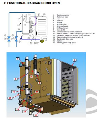
2.1. Open valve operation
The rotation of the fan creates a vacuum effect in the local area behind his disk back where it faces the suction pipe/exhaust 5. When the butterfly valve 7 is open to this effect a vacuum sucking air flow entering through the pipe 5. Simultaneously the moist air inside the cooking chamber is induced to leave through the vent tube 6, aided by a flow diverter (not shown) placed inside the chamber at the exit hole. Through the injector 12 is sprayed
water into the vent pipe – especially at high temperatures – in order to cool and condense
the flow of moist air coming out. The condensate is collected on the bottom of the pipe to
siphon 6 and conveyed through the rubber hose 14.
| Alarm on display | Problem (on the manual) | Solution (on the manual) | Note (on the manual) | Note for Service |
|---|---|---|---|---|
| E02:— | The product
core probe has failed. (Circuit open) |
Check the position of the product core probe or inform the after-sales service if it is faulty. | Cooking cycles with product core probe cannot be carried out. | Same as above |
| E03:CC | The steam discharge probe has failed.
(Short circuit) |
Inform the after-sales service. | Convection
and steam cooking |
Check the drain probe. The resistance value must be about 1100 Ohm at 25°C. The probe is connected to the terminals 48 and 49 of the power PCB. |
| E03:— | The steam discharge probe has failed.
(Circuit open) |
Inform the after-sales service. | Convection
and steam cooking |
Same as above. |
| E04 | The motor- operated valve is not positioned correctly. |
Switch on the oven again and if the problem persists inform the after- sales service. | Convection and steam cooking cycles can still be carried out. |
Check that the motor-operated valve is
not blocked. The motor is connected to pole 11. The micro-switch terminals C and NC are connected to the terminals 3,15 A fuse (delayed) on the relays PCB. |
| E05 | Safety thermostat failure. | Inform the after-sales service. | The oven’s
functions are disabled so no cooking |
Reset the safety thermostat. Check that the thermostat capillary is not bent, squeezed or broken. Test the oven at the maximum temperature for some minutes. |
| E06 | Motor overload tripped. | Inform the after-sales service. | The oven’s
functions are disabled so no cooking |
Reset the motor overload protection
relay (L1 and L2) or reset the alarm from the keyboard (L3). For L3 only, check the inverter alarm list. Check the motor to rotate free and the 3 phases |
| Alarm on display | Problem (on the manual) | Solution (on the manual) | Note (on the manual) | Note for Service |
| E07 | Power board alarm | Inform the after-sales service. | The oven’s
functions are disabled so no cooking |
Control the dip switch settings of the power board. The switches 1, 2, 3, and 4 of the DP1 must be set to OFF. |
| E08 | The vacuum probe has failed. | Press reset button. Check if the vacuum probe is correctly connected to the plug on the control board. | Connect and
disconnect the vacuum probe only when the oven is not working. If the problem persists, call the after-sales service. |
Check the vacuum probe. The resistance value must be about 1100 Ohm at 25°C. The probe is connected to the terminals 50 and 51 of the panel PCB. Verify the connector terminals are clean and be sure to follow the user instructions. |
| E09 | Exceeded
maximum temperature allowed in room (Probe is set to |
Inform the after-sales service. | The oven’s
functions are enabled so cooking |
Check the chamber probe, and check the contactors are non blocked |
| E10 | Electrical component compartment has overheated. | The oven solves the problem on its own. | The oven’s functions are enabled so cooking cycles can be carried out. |
The chamber heating will be
temporarily disabled. Check the panel board cooling fan. Remove and clean the air gratings located on the front of the oven. This alarm will be automatically reset when the temperature drops down. |
| E11 | Electronic circuit board diagnostics tripped. | Inform the after-sales service. | The oven’s
functions are disabled so no cooking |
This alarm will appear in the case the alarm E10 has not been removed and the temperature on PCB has rised up to 69°C. Follow the above instructions. |
Closed valve operation
With the valve closed, the steam can not escape from the vent pipe 6, or from the tube 5 at least until the pressure inside the cooking chamber is not sufficient to overcome the effect of decompression generated by the rotation of the fan (usually 1,5-2,0 mBar). But when the pressure chamber exceeds the decompression generated by the fan, the steam
excess is expelled through the tube 5. The system operates as a closed system, where the overpressure valve (overpressure valve in the FM ovens) is dynamically replaced by the effect of decompression generated by the fan. Even in this mode, water is sprayed by the injector 12 in order to maintain the siphon full. Note that, unlike than the FM, the condensate tube 14 is connected upstream of the swing of the siphon, as with the motorised valve closed the vent pipe 6 and the drain tube 14 are at the same pressure of the cooking chamber. The two modes of operation described above are used in different modes of cooking in the following way: Convection cooking: means the user can determine the % the vent valve is open according to the diagram below. 0% -vent completely open (bar on the display all red)
from 10 to 90% – the valve opens and closes in timed mode, the value shown on the display is the % of time that remains closed. 100% – vent completely closed (bar on the display all grey) Combi cooking mode: the user can set the desired % of steam – the opening and closing of the vent valve is controlled automatically by the oven, based on values detected from
the apposite humidity probe. Steam cooking: valve remains closed.
| Alarm on display | Problem (on the manual) | Solution (on the manual) | Note (on the manual) | Note for Service |
|---|---|---|---|---|
| E13 | Electronic circuit board diagnostics tripped. | Inform the after-sales service. | The oven’s functions are disabled so no cooking cycles can be carried out. |
Communication failure between the
boards or peripheral devices. Verify electrical connections. E13c= Inverter 2 E13d= Combustion control board 2 |
| E14 | Electronic circuit board diagnostics tripped. | Inform the after-sales service. | The oven’s
functions are disabled so no cooking |
PCB temperature probe failure. Replace the power board or the CPU board. E14V = CPU E14Q = power board |
| E19 | The humidity probe has failed. | Inform the after-sales service. | The oven’s
functions are enabled so cooking |
Check the connector terminals on the probe and on the power board. |
| E20 | Configuration error | Inform the after-sales service. | The oven’s functions are disabled so no cooking cycles can be carried out. |
Found inconsistencies between the type of oven and installed boards. Verify the installed boards (display, power board) and devices (inverter and combustion control), verify their proper connection on net cables and repeat the configuration of the oven. |
| E21 – E26 | Washing cycle alarms | See chapter 5.4 | ||
| E27 | Gas test missed | See chapter 4.8 (alarm gas chart) |
Drain cooldown / steam condensing operation
The inlet water assembly 11 feeds the cooling water injector 12. The opening of the water solenoid valve is timed based on the mode of operation (convection, combi or steam), chamber temperature and the temperature detected by temperature sensor 9. The inlet water assembly 11 is different depending on the levels:
Level 3
It consists of:
– Non return valve EN1717 (for washing)
– Pressure reducer (for washing)
– Double water solenoid valve (one is for washing)
– Pressure switch on the drain cooldown line
– Pressure switch and manometer on the washing water line
Note: the water pressure adjustment should be done during a washing cycle.
Level 2 & BX
It consists of:
– Double water solenoid valve (one is for cleaning)
– Pressure switch on the drain cooldown line
– Pressure switch on the washing water line (not for BX MY2016)
– Pressure reducer (only models FX201-202)
Level 1
It consists of:
– Single water solenoid valve
3. ELECTRONIC BOARDS, INVERTER, FUSES, OVERLOAD
RELAYS
3.1. Electronic boards level 3 general layout
The electronic boards system comprises:
1. panel group:
o CPU board 1a
o display LCD board 1b
o keyboard (glued to the glass panel) 1c
o LED board 1d
2. power PCB
3. combustion control PCB (only gas model)
4. inverter
5. USB connector
6. transformer
7. on/off switch – 12V AC
| Alarm on display | Problem (on the manual) | Solution (on the manual) | Note (on the manual) | Note for Service |
|---|---|---|---|---|
| E28 | Valve not working | Press reset button | The oven’s
functions are enabled so cooking |
Check the connector terminals on the valve and on the power board. |
| E29 | Core probe not inserted | Press reset button | The oven’s
functions are enabled so cooking |
— |
| E30 – E38 | Electronic circuit board diagnostics tripped. | Press reset button | If the problem persists inform the after-sales service. | Protections against electromagnetic
interferences. Check all the ground wiring of the equipment. In case of gas version, please check ignition electrode and cover protections to be properly fitted. Check all the wirings relative to the ignition system. Check the correct insulation of the cable. |
| E80 – E85 | — | — | Inform the
after-sales service. |
— |
CPU board (1a) controls the display panel (1b), keyboard (1c) and the LED board (1d).
The connections with these boards are made with flat cables. Addition, the CPU board (1a) communicates with the power board (2) through a network cable (RJ45) and with the external USB port (5). The power board (2) receives all the signals from the oven probes (PT1000 temperature sensors, door micro switch, core food probe, etc.) and controls all organs of the oven through the appropriate relays. It communicates with the CPU board (1a), with the inverter
(4) and the combustion control board (3) (only for gas) via RJ45 network cables. If there is no communication between the power board (2) and the CPU board (1a) or the board or the inverter or the combustion control board a warning alarm appears E13 (communication error alarms, see table). The management programme of the oven consists of three parts:
Firmware (FW) – it controls the operation of the oven (inputs and outputs) – it is in the
power board (2) Software (SW) – Contains all the user interface, programs, pictures, etc.. – it is in the CPU
Operating System (OS) – it is in the CPU Versions of OS, SW and FW are shown in the upper part of the Service menu
| Alarm on display | Alarm description | Notes |
|---|---|---|
| A01 | High chamber temperature | In positive storing the temperature of the chamber remained higher than 12°C for more than 60 minutes
In negative storing the temperature of the chamber remained higher than -10°C for more than 60 minutes |
| A02 | Low chamber temperature | In positive storing the temperature of the chamber remained lower than -8°C for more than 60 minutes
In negative storing the temperature of the chamber remained lower than -30°C for more than 60 minutes |
| A03 | Temperature limit | In chilling or freezing the temperature of the core probe or the chamber probe is higher than 90 ° C |
| A04 | Chamber probe | Chamber probe failure |
| A05 | Evaporator probe | Evaporator probe failure |
| A06 | Condenser probe | Condenser probe failure |
| A07 | Condenser dirty | Condenser dirty |
| A08 | Core probe (needle tip) | Core probe failure |
| A09 | Core probe (under- surface) | Core probe failure |
| A10 | Core probe (external) | Core probe failure |
| A11 | Power board probe | Power board probe failure |
| Alarm on display | Alarm description | Notes |
| A12 | Power board over temperature | The temperature of the power board exceeded 70°C |
| A13 | Door open | The door remained open longer than 120 seconds |
| A14 | Blackout | There was a lack of power for a long time |
| A15 | High pressure | The high pressure switch has detected a fault. |
| A16 | Low pressure | The low pressure switch has detected a fault. |
| A17 | Compressor overload | The compressor overload has tripped |
| A18 | Communication failure | Missing communication between the CPU and the power board |
| A20 | Internal alarm of the power board | There has been an anomaly power board. |
Versions:
O.S.: 1.9
The operating system, indicates the date issued and version used in that machine. The issue date of O.S. is unique and allows the user to know the last upgrades of the oven.
SW: 2.01
SW: Software of the LCD display board, indicates the date issued and the version of software installed on the CPU (1a).
The issue date of the SW is unique and allows the user to know the last upgrades of the
software interface of oven.
FW: E4FD
FW: Firmware of power PCB, reports the checksum of the firmware version installed on the power board. The checksum of the FW of the power board are unique and allow the user to know the level of the firmware update of the oven.
Oven Type: From this window you have to select the type of the oven. The selection of the type of
oven must be done every time you replace any board (1a, 2, 3, 4) to realign the
parameters of that oven.
The selection of the oven automatically starts the configuration process during which the
devices present are tested. At the end of the configuration the oven shows the list of
devices found: check that the devices are the same as those installed.
If the devices do not match check again the oven and repeat the process of configuration.
How to configure the type of oven
The setup process of the oven must be done after replacing one of the following
components: CPU board, power board, inverter, combustion control board. It is required to
make all the boards communication with one another and to select the correct operating
parameters of the oven.
Operate as follow:
– Enter the service menu
– Select the “oven type”
– Select the type of oven
– Wait until the end of the procedure and check the list of devices in comparison with
the table below.
– If you get the alarm E20 during the procedure, reset with the reset button and repeat the procedure by pressing the function “repeat configuration”. If the problem persists, verify the items found and control the wiring of the components not detected.
– If at the end of the procedure, the screen does not match the table below, check the wiring and repeat the configuration by pressing “repeat configuration”.
– If the configuration is correct (the screen corresponds to the table) press “OK”. Alarm log: Selecting this voice you get the list of the last thirty alarms that have occurred on the oven. The list will show you the alarm code, date and time.
Temperature: Allows you to configure the temperature unit used in the normal operation of the oven. The choices can be °C or °F. To change the setting, put the cursor on the line “Temperature” and select the new unit pushing the knob.
Water Hardness: Allows you to set the parameter of hardness of water. This determines the quantity of chemicals and water used during washing, Update SW, FW: This selection start the process of updating the software on the CPU
(1a) and the firmware on the power board. Before performing the upgrade the USB stick (recommended max. size 4GB) should be inserted into the connector (the stick must be formatted FAT or FAT32 and contain a
directory “AngeloPo” with all the necessary files inside).
How to update software and firmware
To update the software and firmware, proceed as follows:
– Enter the service menu
– Insert the key into the USB connector
– Select “Update SW, FW”
– Wait until the end of the procedure and follow the instructions that appear on the display
– During this procedure the message “turn off and on the oven” will appear. This has to be done by the green power switch. Attention! Don’t remove the USB Stick! (if you switch from version 1.x to 2.x, the system will require a second reboot, again without removing the USB stick!)
– Remove the USB stick only when the complete update has been finished (when the main menu is displayed)
WARNING In case of power loss during this procedure, both the electronic boarding could be
damaged beyond repair Update parameters: This selection starts the procedure for updating parameters of the
boards without the USB stick. It is performed normally when you change the power board 2 or the CPU 1a in order to align the parameters of the boards. To activate the update enter the password FA53.
How to update the parameters (SW and FW alignment)
This procedure allows the user to align the parameters of the boards after replacing the
CPU board or power board. The procedure is performed after replacing the card, as
follows:
– Enter the service menu
– Select ” Update parameters “
– Enter the password “FA53”
– Wait until the end of the procedure and follow the instructions that appear on the display
When the procedure has finished, turn off and on the oven as written on the display. Oven Number: identification number of the oven within a network of ovens. It is used during HACCP data download as not to create conflicts within the network and to uniquely identify the data from each appliance. Testing APGC: this choice is subject to Password and is used only at the end of the test cycle into the factory before the oven is shipped to the final customers. Display gas: allows visual check, during normal operation of the machine, the parameters and the states of the gas unit. It must be repeated each time the machine is switched on. Gas setup: this option allows you to enter into the gas setup, the password is SI74. RH% Calibration: This selection allows you to activate the calibration procedure of the UR probe (humidity probe). The procedure takes about 10 minutes to run. The procedure is performed with the oven cold and finish with the oven at 230 ° C. This procedure should be performed every time you replace the UR probe or whenever you replace the
power board (2).
Clean test: See chapter 653.
Pump unit selection: set 0 if is installed the black/brown pumps unit, set 1 if is installed the blue pumps (first version).
T/RH display: This option is for internal use of Angelo Po. Counters: displays the numbers of washing programs performed and the working times at low and high temperature
Counters from software version 1.16L: displays the numbers of washing programs performed completely or interrupted. In addition is possible to download all the data distinguishing those made above 250° or under that limit.
With an USB memory inserted in the slot, and pressing “download”, in the above screen
the washing, data will be downloaded in the same format as HACCP data. Pressing “details” will appear the following screen where is possible select a date. For each date the screen displays the types of washing done, start time, end time, and if an alarm has occurred during washing cycle displaying the icon
From the previous screen, pressing “display alarms” will be showed the same screen displayed for HACCP data, the soft key will switch on “show acquisitions” pressing on it will end in the return to the list of washes. Choose language on switch on: When set to ON, on the next switch on of the oven, the user can set the appropriate language without entering the menu “Settings”. Core probe warning: This option is for internal use of Angelo Po. OS update: This option is subject to password and is for internal use of Angelo Po. Restore Factory PSW: Replaces the user entered password with the password APGC. To be used if the user forgets their password. The oven will still be delivered with the factory password APGC, Blast Chiller: ON or OFF depending if there’s installed a blast chiller controlled by the oven.
3.4. Emergency Software Recover Procedure
In case of fault during boot-strap or a power loss during Firmware update might be necessary turn on the equipment with the emergency recover procedure. To operate the procedure is mandatory to have available an USB memory prepared as described at page 26 with the last firmware release. To activate it need to insert the memory at oven turned off, and turn it on keeping press down the encoder until the update splash screen will appear, and follow the standard
procedure.
3.5. Inverter
The inverter keyboard is disabled as the operating parameters are sent to the inverter via power board. This component allows us to select up to five motor speeds and the static way of cooking, with fan stops (when the heating element is inactive). The inverter is equipped with a heat dissipater and a cooling fan situated at the bottom of the item. The inverter inner temperature is monitored by an internal temperature sensor, if the temperature exceeds 50° C, the inverter blocks (show the alarm E06: 8 see alarms table).
The over temperature alarm may be due to rupture of the cooling fan, in which case you can replace the single cooling fan. The speeds could be selected between 0 – 600 – 800 – 1100 – 1400 – 1500 rpm
3.5.1. Warning on electric hazard
Once you remove the power supply on the oven, you have to wait 3 minutes before starting maintenance on the inverter or the motor due to electrical hazards.
E06:3 The inverter bus voltage is lower than
85% of the nominal value check the inverter voltage (220VAC)
E06:4 the inverter bus voltage has dropped
below the minimum allowable check the inverter voltage (220VAC)
E06:5 the inverter bus voltage has raised up
to the maximum allowable check the inverter voltage (220VAC)
E06:6
The inverter is not able to turn the
motor
check that the motor is free to move. Check that
the three phases are connected to the motor.
E06:7 Motor overload
check that the motor is free to move and doesn’t
touch any other item
E06:8 Excessive heating of the dissipater
verify that the ambient temperature is below
50°C. Verify that the cooling fan inside the
inverter works properly
E06:12 The output current too high
check that the motor is free to move and doesn’t
touch any other item
E06:13
Found scattered current too high
between one of the phases and earth.
check that one or more phases of the motor
power supply are not short circuited with the
mass
E06:33 Automatic restart failed
There was an alarm 4, 5, 6, 7, 8, 12 or 63, but
the automatic restart was unsuccessful. Remove
the cause of these alarms and restart.
E06:38 Phase U short circuited with GND
check the correct connection of the motor and
check that the phase U of motor supply is not
short circuited to the GND
E06:39 Phase V short circuited with GND
check the correct connection of the motor and
check that the phase V of motor supply is not
short circuited to the GND
E06:40 Phase W short circuited with GND
check the correct connection of the motor and
check that the phase W of motor supply is not
short circuited to the GND
E06:41 between phases a UV excess current
flows
check the correct connection of the motor and
that the phases U and V of the motor power
supply are not short circuited together
E06:42 between phases a UW excess current
flows
check the correct connection of the motor and
that the phases U and W of the motor power
supply are not short circuited together
E06:43 between phases a VW excess current
flows
check the correct connection of the motor and
that the phases V and W of the motor power
supply are not short circuited together
E06:64 High current limit exceeded 150% for 1
minute or 200% for 3 seconds
check that the motor is free to move and doesn’t
touch and other item
E06:70 inverter power section faulty Check the inverter voltage (220VAC
E06:71 Excessive communication errors
check that the cable connecting the serial line is
properly connected.
E06:81 Communication breakdown
check that the cable connecting the serial line is
properly connected.
E06:100 Inverter checksum error Replace the inverter
E06:122 Inverter control section faulty Replace the inverter
E06:255 Inverter blocked
check the connection between terminal 1 and
terminal 11 on the inverter.
SUZUMO SUSHI ROLL MACHINE ERROR CODE
Sushi roll machine troubleshooting and error code , how to repair step by step and Instruction Manual Sushi Roll Machine.SUZUMO[wdcl_logo_carousel nav_pagi=»none» is_variable_width=»on» custom_cursor=»on» _builder_version=»4.16″ _module_preset=»default»…
HOBART DISHWASHER SERVICE CODE AND SERVICE MANUAL
ECOMAX DISHWASHERSYMPTOM Machine cannot beswitched on.The ON/OFF buttonLED does not flash oris permanentlyilluminated.Also see page 4POSSIBLE CAUSE — Power supply has been cut off on site.- Control fuse F1 faulty.- No power supply of 230V (L1) at the boardA1, terminal…
RATIONAL SCC ERROR CODE AND SERVICE MANUAL
Rational Oven Error Code | Wiring Diagram | Software Up-Date | Service Manual | Spare Parts.[wdcl_logo_carousel nav_pagi=»none» is_variable_width=»on» custom_cursor=»on» _builder_version=»4.16″ _module_preset=»default» global_colors_info=»{}»…
ALTO-SHAAM ERROR CODE AND SERVICE MANUAL
Alto Shaam Error Code | Service Manual | Machine Diagnostic |User Manual | Wiring Diagram | Software Download Provide Alto-Shaam Combitherm countertop Model CTX4-10EC flash-steam electric CombiOven designed with EcoSmart technology for reduced energy usage and include…
MKN OVEN ERROR CODE
MKN Combi Oven Error Code | Service Manual | Wiring Diagram | Troubleshooting | How to do Diagnose the Machine.[wdcl_logo_carousel nav_pagi=»none» is_variable_width=»on» custom_cursor=»on» _builder_version=»4.16″ _module_preset=»default» global_colors_info=»{}»…
CONVOTHERM OVEN ERROR CODE AND SERVICE MANUAL
Convotherm oven errorcode | Service Manual | Troubleshooting | Diagnose | User Manual | Spare Parts. [wdcl_logo_carousel nav_pagi=»none» is_variable_width=»on» custom_cursor=»on» _builder_version=»4.16″ _module_preset=»default» global_colors_info=»{}»…
ELOMA OVEN ERROR CODE AND WIRING DIAGRAM
Eloma Error Code | Service Code | Wiring Diagram | Software Up-Dtaes Free | Service Manual | User ManualEloma Combi-steamer Multimax A, Multimax B, Genius T, Joker B, Joker TEloma Bake-Off Oven EB 30, EB 50, EB 80, version B and TAccess and saving of the…
RATIONAL OVEN WE ERROR CODE AND SERVICE PROGRAME
Service Code|Troubleshooting|Error Messages|Wiring Diagrame|Software Up-Dates|Error Code[wdcl_logo_carousel nav_pagi=»none» is_variable_width=»on» custom_cursor=»on» _builder_version=»4.16″ _module_preset=»default» global_colors_info=»{}»…
- RATIONAL
- CONVOTHERM
- MKN
- ELOMA
- HOBART
The unit will only function properly, when all components are designed correctly and the installation is done according to the manufacturers instructions.
Therefore during maintenance and troubleshooting it is mandatory to observe all components together with the connected services such as electricity, water etc. and the kitchen surrounding and venting.
Every deviation from the installation manual can cause different errors
In order to ensure that the combi
steamer is in perfect technical
condition, the manufacturer
recommends maintenance by
authorized after-sales service
personnel at least once per year.
The frequency converter is fitted with a wide range input. The input voltage can be configured with the link plug (Jumper) J1
Input voltage at the mains terminal inlet can be measured according to the following Jumper status
the installation manual! It is oblige to follow the installation instructions to get a valid
warranty from Eloma and to ensure that the purchased appliances
can be operated correct
-
Contents
-
Table of Contents
-
Bookmarks
Quick Links
LEVEL 1 and 2
LEVEL 3
LEVEL 2
Rev.1
Copyright by Servizio Clienti ANGELO PO Spa
1
Related Manuals for Angelo Po FX Series
Summary of Contents for Angelo Po FX Series
-
Page 1
LEVEL 1 and 2 LEVEL 3 LEVEL 2 Rev.1 Copyright by Servizio Clienti ANGELO PO Spa… -
Page 2: Table Of Contents
Adjustment during the test………………….64 4.5. Problems during the test setup wizard…………………67 4.6. Gas flue analysis……………………..68 4.7. Installation report……………………..69 4.8. Gas alarms and burner problem solving ……………….71 4.9. Gas conversion ……………………..74 4.10. Levels 2: Gas test ……………………..75 Copyright by Servizio Clienti ANGELO PO Spa…
-
Page 3
Blower fan replacement ……………………108 7.14. CPU and display LCD boards (LIV.3) replacing …………….109 7.15. CPU and display LCD boards (LIV.3) replacing (2 version)…………115 7.16. Roll-In adjustment RX201 — RX202………………..117 7.17. Scheduled recommended maintenance ………………119 ALARMS …………………………120 Copyright by Servizio Clienti ANGELO PO Spa… -
Page 4: Commercial Model Number
1. COMMERCIAL MODEL NUMBER ( 2 – 3 ) Copyright by Servizio Clienti ANGELO PO Spa…
-
Page 5
WITH RIGHT FX61G2R FX101G2R OPENING DOOR FX61G3R FX101G3R FX61E2CR FX101E2CR SPECIAL VERSION FX61E3CR FX101E3CR WITH FAT DRAIN AND RIGHT FX61G2CR FX101G2CR OPENING DOOR FX61G3CR FX101G3CR FX201E2P FX201E3P SPECIAL VERSION FOR PASTRY FX201G2P FX201G3P Copyright by Servizio Clienti ANGELO PO Spa… -
Page 6
FM GAS POWER (KW) DELTA % 16,7% 8,3% 25,0% 12,5% 20,35% 14,6% FX ELECTRICAL POWER 17,8 35,5 (KW) FM ELECTRICAL POWER 17,8 35,5 17,9 (KW) DELTA % 0,0% 0,0% 0,0% 11,7% 0,0% 0,0% Copyright by Servizio Clienti ANGELO PO Spa… -
Page 7: Connection Diagram Electric And Gas
1.1. Connection diagram electric and gas OVEN CONNECTION DIAGRAM (FX122E3) Copyright by Servizio Clienti ANGELO PO Spa…
-
Page 8
OVEN CONNECTION DIAGRAM (FX122G3) Copyright by Servizio Clienti ANGELO PO Spa… -
Page 9: Water Characteristics
The appliance must be supplied with drinking water having the characteristics shown in the table. If these characteristics are not complied with, the appliance might suffer damage; a water treatment device should therefore be installed. Copyright by Servizio Clienti ANGELO PO Spa…
-
Page 10: Functional Diagram Combi Oven
2. FUNCTIONAL DIAGRAM COMBI OVEN Copyright by Servizio Clienti ANGELO PO Spa…
-
Page 11: Open Valve Operation
— especially at high temperatures — in order to cool and condense the flow of moist air coming out. The condensate is collected on the bottom of the pipe to siphon 6 and conveyed through the rubber hose 14. Copyright by Servizio Clienti ANGELO PO Spa…
-
Page 12: Closed Valve Operation
Note that, unlike than the FM, the condensate tube 14 is connected upstream of the swing of the siphon, as with the motorised valve closed the vent pipe 6 and the drain tube 14 are at the same pressure of the cooking chamber. Copyright by Servizio Clienti ANGELO PO Spa…
-
Page 13
Combi cooking mode: the user can set the desired % of steam — the opening and closing of the vent valve is controlled automatically by the oven, based on values detected from the apposite humidity probe. Steam cooking: valve remains closed. Copyright by Servizio Clienti ANGELO PO Spa… -
Page 14: Drain Cooldown / Steam Condensing Operation
It consists of: — Double water solenoid valve (one is for cleaning) — Pressure switch on the drain cooldown line — Pressure switch on the washing water line — Pressure reducer (only models FX201-202) Copyright by Servizio Clienti ANGELO PO Spa…
-
Page 15: Steam Producing Operation
Back flow preventer 2.4. Steam producing operation Copyright by Servizio Clienti ANGELO PO Spa…
-
Page 16: Electronic Boards For Levels 2-3, Inverter, Fuses, Overload Relays
LCD board 1b keyboard (glued to the glass panel) 1c LED board 1d 2. power PCB 3. combustion and fan control PCBs (only gas model) 4. inverter 5. USB connector 6. transformer 7. on/off switch Copyright by Servizio Clienti ANGELO PO Spa…
-
Page 17
4. Inverter 1. Control panel The control panel has to be connected always on the 1 connector 2. Power board and Switch 3. Combustion Control board and Blower Control board Copyright by Servizio Clienti ANGELO PO Spa… -
Page 18
5. USB plug 1b. LCD display 1a. CPU board 1d. LED board 1c. Keyboard Copyright by Servizio Clienti ANGELO PO Spa… -
Page 19
2 FW Transformer 2x 12Vac outputs (fused) to the electronic boards Copyright by Servizio Clienti ANGELO PO Spa… -
Page 20
Software (SW) — Contains all the user interface, programs, pictures, etc.. – it is in the CPU Operating System (OS) – it is in the CPU Versions of OS, SW and FW are shown in the upper part of the Service menu. Copyright by Servizio Clienti ANGELO PO Spa… -
Page 21: Service» Menu
O.S.: 1.9 The operating system, indicates the date issued and version used in that machine. The issue date of O.S. is unique and allows the user to know the last upgrades of the oven. Copyright by Servizio Clienti ANGELO PO Spa…
-
Page 22
At the end of the configuration the oven shows the list of devices found: check that the devices are the same as those installed. If the devices do not match check again the oven and repeat the process of configuration. Copyright by Servizio Clienti ANGELO PO Spa… -
Page 23
Operate as follow: Enter the service menu Select the «oven type» Select the type of oven Copyright by Servizio Clienti ANGELO PO Spa… -
Page 24
Temperature: Allows you to configure the temperature unit used in the normal operation of the oven. The choices can be °C or °F. To change the setting, put the cursor on the line «Temperature» and select the new unit pushing the knob. Copyright by Servizio Clienti ANGELO PO Spa… -
Page 25
How to update the parameters (SW and FW alignment) This procedure allows the user to align the parameters of the boards after replacing the CPU board or power board. The procedure is performed after replacing the card, as follows: Copyright by Servizio Clienti ANGELO PO Spa… -
Page 26
Pump unit selection: set 0 if is installed the black/brown pumps unit, set 1 if is installed the blue pumps (first version). T/RH display: This option is for internal use of Angelo Po. Counters: displays the numbers of washing programs performed and the working times at low and high temperature. -
Page 27
Core probe warning: This option is for internal use of Angelo Po. OS update: This option is subject to password and is for internal use of Angelo Po. Restore Factory PSW: Replaces the user entered password with the password APGC. To be used if the user forgets their password. -
Page 28: Explanation Table
Note: After replacing one of the items listed above, at the first ignition of the oven you may see alarms E13 and / or E20. After following the procedures listed in the table the alarms should no longer appear. Copyright by Servizio Clienti ANGELO PO Spa…
-
Page 29: Inverter
Cooling fan Once you remove the power supply on the oven, you have to wait 3 minutes before starting maintenance on the inverter or the motor due to electrical hazards. Copyright by Servizio Clienti ANGELO PO Spa…
-
Page 30
GND check the correct connection of the motor and E06:40 check that the phase W of motor supply is not Phase W short circuited to GND short circuited to the GND Copyright by Servizio Clienti ANGELO PO Spa… -
Page 31
E06:100 Inverter checksum error Replace the inverter E06:122 Inverter control section faulty Replace the inverter check the connection between terminal 1 and E06:255 Inverter blocked terminal 11 on the inverter. Copyright by Servizio Clienti ANGELO PO Spa… -
Page 32: Electronic Boards Level 2 General Layout
1. control panel assembly, it is made of: o CPU board 1a o keyboard (glued to the glass panel) 1b 2. power PCB 3. combustion and fan control PCBs (only gas model) 4. inverter 5. transformer 6. on/off switch Copyright by Servizio Clienti ANGELO PO Spa…
-
Page 33
2. Power board 2. Power board 1. Control panel The control panel has to be connected always on the 1 connector 3. Combustion control board and blower control board Copyright by Servizio Clienti ANGELO PO Spa… -
Page 34
1b. Keyboard 1a. CPU board Copyright by Servizio Clienti ANGELO PO Spa… -
Page 35
(3) (for gas model only) via RJ45 network cables. If there is no communication between the power board and the CPU board or the combustion control board the alarm E13 appears (communication failed error). Copyright by Servizio Clienti ANGELO PO Spa… -
Page 36
(° C or ° F). b) Press the “time” button and turn the knob to set the automatic preheating c) Hold the «washing» button for at least 3 sec to see the SW and FW versions. Copyright by Servizio Clienti ANGELO PO Spa… -
Page 37
» USb » is steady and also turns on the START / STOP button in green color. The stick (recommended max. size 4GB) must be formatted FAT or FAT32 and contain a directory «AngeloPo_L1_L2» with all the necessary files inside). . Copyright by Servizio Clienti ANGELO PO Spa… -
Page 38
If the configuration is incorrect check the connections between the boards and press the knob to repeat the configuration. o If the configuration is correct press the «start / stop» button to exit. Copyright by Servizio Clienti ANGELO PO Spa… -
Page 39
61E2, 82E2, 101E2, 122E2 1 — 0 201E2, 202E2 2 — 0 61G2, 82G2, 101G2, 122G2 1 — 1 201G2, 202G2 2 — 2 Oven type Number of Number of Combustion Control Inverters boards Copyright by Servizio Clienti ANGELO PO Spa… -
Page 40: Explanation Table
Note: After replacing one of the items listed above, at the first ignition of the oven you may see alarms E13 and / or E20. After following the procedures listed in the table the alarms should no longer appear. Copyright by Servizio Clienti ANGELO PO Spa…
-
Page 41: Fx Fuses Description
Blower control pcb: F1- board general fuse (4A F), blower and combustion control board supply circuits. Combustion control pcb: F1—— board general fuse (6,3A T), protects also gas valve supply circuit. NOTE: T=slow, F=fast. Copyright by Servizio Clienti ANGELO PO Spa…
-
Page 42: Operation Testing, Adjusting, Installation Report, Gas Circuit Alarm
To make this adjustment it is necessary to use a gas flue analyzer. Furthermore, an electronic variable-speed blower, controlled by the power board, allows you to change the quantity of the air-gas mixture. Copyright by Servizio Clienti ANGELO PO Spa…
-
Page 43: Power Schemes
Full power*: operating at maximum capacity and blower engines at full speed, the • inlet gas circuit is in total decompression and the gas valve adjustment of the valve does not cause significant differences. The combustion is totally dependent on the nozzle installed. Copyright by Servizio Clienti ANGELO PO Spa…
-
Page 44
* With the PLUS function turned off the oven works with maximum set at 90% of maximum power, to use 100% of the power it is necessary to enable the PLUS function. NOTE: — The burner ignition occurs at a power of about 10% higher than the minimum (40-50%). Copyright by Servizio Clienti ANGELO PO Spa… -
Page 45: System Components
— As the gas inside the tube (7) and the fitting (3) is at negative pressure, in case of leak to find it don’t use flame because it could be sucked in the mixer and cause a fire / explosion. Copyright by Servizio Clienti ANGELO PO Spa…
-
Page 46
Functional diagram gas system Copyright by Servizio Clienti ANGELO PO Spa… -
Page 47: Gas Valve ( Csa Approved)
4.2.1. Gas valve ( CSA approved) 120 VAC between terminals 3 and 4 Compensation pipe Copyright by Servizio Clienti ANGELO PO Spa…
-
Page 48: Mixer
Check that the draft air tube is free of cuts or tears and that the clamps are tight Check the connections tightness; do not use flames on gas burner because they could be sucked into the mixing circuit and cause fire / explosion. Copyright by Servizio Clienti ANGELO PO Spa…
-
Page 49: Air Blower Fan
Air blower fan Power supply 115 volts AC Modulation control NOTES: Do not force the connector of the modulation control, it is one way inserting. The blower speed is controlled by the blower control board. Copyright by Servizio Clienti ANGELO PO Spa…
-
Page 50: Blower Control Board
On the level 3 models the microAmpere reading can be displayed. It is possible to activate this function from the Service menu; the reading needs to be divided by 10 (e.g. 32 / 10 = 3,2 microAmpere). Copyright by Servizio Clienti ANGELO PO Spa…
-
Page 51: Combustion Control Board
The reading must be about 3,5 µA DC; in order to check it, take the mesure in series between the flame detector and the terminal n°8 on the combustion control board, as shown in the drawing. 4.2.5. Combustion control board Copyright by Servizio Clienti ANGELO PO Spa…
-
Page 52: General Functional Diagram
REQUEST PHASE RECEIVED NEUTRAL 120 V 100 – 240 V 120 V INVERTER POWER SUPPLY 120 V LOCKOUT ALARM 120 V BURNER-ON RS485 FEEDBACK COMMUNICATION CLOSE ON POWER REQUEST 120 V LOCKOUT RESET Copyright by Servizio Clienti ANGELO PO Spa…
-
Page 53: Spark Plug And Flame Detector Kit
— The spark plug needs scheduled maintenance, see section 4.10. — We recommend the replacement of the gasket each spark plug replacement. — The spark plug kit is one way fixing (see picture). Copyright by Servizio Clienti ANGELO PO Spa…
-
Page 54: Burner
4.2.8. Burner INSULATING MATERIAL COIBENTANTE NOTES: Replace the insulation panel at any replacement of the spark plug kit, if necessary. Copyright by Servizio Clienti ANGELO PO Spa…
-
Page 55: Heat Exchanger
4.2.9. Heat exchanger FX heat exchangers are more efficient because they have more exchange surface than FM ones: +18% 101: +13% +22% 122: +10% 201: +13% 202: +10% Copyright by Servizio Clienti ANGELO PO Spa…
-
Page 56: Exhaust Extraction Kit
If the oven is not positioned under a fume hood, you can use the Exhaust extraction kit to make a connection to an exhaust system. It is absolutely prohibited the direct connection to the outside. A type installation only! Copyright by Servizio Clienti ANGELO PO Spa…
-
Page 57: Blower Control Board: Logic Operation
This step will remain until the power is requestd and/or until an alarm occurs, then step 10 is selected. STOP: burner turned off. The blower is set to stop. The blower control check for alarm from Burner Control Copyright by Servizio Clienti ANGELO PO Spa…
-
Page 58
If there is any alarm then step 7 and 8 are selected. If there are problems the board turn on state “7” or «8» ( Locked Steps ), showing alarm. For example GAS: F4 can be reset from the panel. Copyright by Servizio Clienti ANGELO PO Spa… -
Page 59: Ignition Standard Cycle
The diagram shows 2 ignition cycles (step 1-5): the first operational phase (step 5) has a modulating working, second, minimum power range working. The difference between the two cycles is the speed of the blower, which varies with the required power. Copyright by Servizio Clienti ANGELO PO Spa…
-
Page 60: Gas Alarm: F4: Flame Missing
After these 3 attempts the combustion control board goes into state «8” the combustion is blocked and the display shows the alarm GAS: F4. The alarm can be reset by the user. The causes may be different, for details please refer to section 4.8 Gas Alarms. Copyright by Servizio Clienti ANGELO PO Spa…
-
Page 61: Gas Setup
(see section 6. Change of Gas). 4. To start the wizard, select «Burner 1. (For models FX201G3 and FX202G3 perform first the procedure on the burner 1 and thereafter on the burner 2). Copyright by Servizio Clienti ANGELO PO Spa…
-
Page 62
Verify that the ignition occurs at the correct speed and that the minimum and maximum speeds reached match those settings. If the gas system doesn’t function properly or the flue combustion values are not included in the ranges indicated, follow the instructions in section 4.4.3 Adjustments. Copyright by Servizio Clienti ANGELO PO Spa… -
Page 63: Recommended Values Of Combustion
± 0,8 0÷100 FX202G. CO2% Range CO2% CO ppm minimum 9,3% ± 0,8 0÷100 Natural Gas G20 Maximum 9,2% ± 0,8 0÷100 minimum 11,5% ± 0,8 0÷100 Propane G31 Maximum 11,1% ± 0,8 0÷100 Copyright by Servizio Clienti ANGELO PO Spa…
-
Page 64: Adjustment During The Test
Once done repeat the wizard test. When the adjustment is finished refit the protective cap of the screw. Attention: the pressure adjustment screw PR.ADJ. has no effect on increasing the power of the oven. Copyright by Servizio Clienti ANGELO PO Spa…
-
Page 65
Select the parameter you want to change and set a different value depending on the problem (see next paragraph). Attention: never increase the maximum blower speed over the value set by the factory. Copyright by Servizio Clienti ANGELO PO Spa… -
Page 66
30% — 65% — Propane VMax 6500 7000 6500 6500 7000 6700 5500rpm — Methane 7000rpm VMax 6000 6000 6000 6000 6500 6000 Propane VAcc 35 — 60% Methane — Propane Ramp 30000 10000-30000 Copyright by Servizio Clienti ANGELO PO Spa… -
Page 67: Problems During The Test Setup Wizard
Important: At the end of each intervention on the gas system must perform the procedure for testing gas by measuring the CO and CO2, and verify that the data is within the fields declared by the manufacturer. Copyright by Servizio Clienti ANGELO PO Spa…
-
Page 68: Gas Flue Analysis
CO2 and CO values. Wait until the measure has stabilized (about 1 minute). The gas analyzer should be calibrated and checked periodically to make precise measures. Recommended analyzer: Testo 327-2. Copyright by Servizio Clienti ANGELO PO Spa…
-
Page 69: Installation Report
When first installed, the installer must fill in all parts of the following installation report and send it to «Angelo Po» within 7 days for the activation of the Warranty. It presents data connection, and in particular must show the power supply, if possible, the mains water pressure (and other available data, e.g.
-
Page 70
CO max: 300 ppm Instrument Used (mark and model):………………………………………………………………… This form, relative to the appliance indicated above, filled-in completely must be sent to Angelo Po SpA within 7 days from installation in order to activate the warranty. Certification: the under-signed, in quality of technician of an Angelo Po authorised after-sales centre, certifies that all of the items on this form have been filled-in correctly and that the unit is installed correctly. -
Page 71: Gas Alarms And Burner Problem Solving
3 fast light + 1 long light = Failure before ignition step or leakage currents from flame signal wire or from his plug. From 8 to 14 fast light + 1 long light: internal failure. Change the burner control board. Copyright by Servizio Clienti ANGELO PO Spa…
-
Page 72
The flame is lighting but after some 3. check the small led on the burner control board for status seconds the flame goes off. informations and/or diagnostic mode. 4. measure the ionization current. Copyright by Servizio Clienti ANGELO PO Spa… -
Page 73
(Pins 4-4 and Pins19-3 between two pcb ). Note: For the 20 grid models appears with the alarm also the number of the burner; 1 stands for the lower burner and 2 stands for the upper burner. Copyright by Servizio Clienti ANGELO PO Spa… -
Page 74: Gas Conversion
2. Setting the type of gas on the display: o enter menu “Service” (Password:SAAP), o enter menu “Setup gas”(Password:SI74), o select the type of gas used from the menu “Type of gas” 3. Perform analysis of flue gas (see section 4.6) Copyright by Servizio Clienti ANGELO PO Spa…
-
Page 75: Levels 2: Gas Test
2. Type of gas: the first display shows the kind of gas: turning the knob is possible to choose the type of gas G20, G25, G30, G31 and Out; the selection is confirmed with enter with the knob. Copyright by Servizio Clienti ANGELO PO Spa…
-
Page 76
5. Start testing: the START/STOP button is on, press it to start the testing phases. 6. STEP 1: Ignition and burner at minimum power. Go to step 2 with button ECO. 7. STEP 2: Burner at maximum power. Go to step 3 with button ECO. Copyright by Servizio Clienti ANGELO PO Spa… -
Page 77
10. Change the dei parameters of the gas board: This adjustment must be done only in according with Service Angelo Po. The parameters into “Step 2” and “Step 3”, are modifiable: press the button TEMPERATURE (red) to change the maximum speed, TIME (yellow) to change the minimum speed, HUMIDITY (green) to change the ignition speed. -
Page 78: Periodic Gas Flue Analysis
2500 working hours. Also in this case you can erase it temporarily by pressing button RESET, and you can work normally with the oven until next switching on. To remove the warning for longer time you must perform Setup Gas and make gas flue analysis. Copyright by Servizio Clienti ANGELO PO Spa…
-
Page 79: Washing Cycles Levels 3
Through this pipe the chemical reaches the nebulizer cleaning in the heat exchanger compartment. PUMP 8 INJECTORS SPRINKLER DETERGENT TANK MIXING PUMP TANK SANITIZER TANK WATER SUPPLY FIXING SPRINKLER WATER SOLENOID PRESSURE NON-RETURN ADJUSTMENT VALVE EN17171 COOKING CHAMBER TO DRAIN SIPHON DRAIN SOLENOID Copyright by Servizio Clienti ANGELO PO Spa…
-
Page 80
Soft clean: 1 detergent dispensing + 1 sanitizer distribution (small amounts) Basic clean: 1 detergent dispensing + 1 sanitizer distribution Medium clean: 2 detergent dispensing + 1 sanitizer distribution Standard clean: 3 detergent dispensing + 2 sanitizer distribution Descaling: 1 sanitizer distribution Copyright by Servizio Clienti ANGELO PO Spa… -
Page 81
— Since version 2.xx each time you switch on the oven, it runs for 5 seconds the dosing pumps, then it opens for 0.5 seconds the rinsing solenoid valve and then it empties the tank for 20 seconds. Copyright by Servizio Clienti ANGELO PO Spa… -
Page 82: Clean Test
During all stages the status of the float shows on the display: it must be open when the tank is empty, it must be closed when the liquid level in the tank exceeds half. Copyright by Servizio Clienti ANGELO PO Spa…
-
Page 83: Washing Interruption
(Ø 9-10 mm). WARNING: on oven level 2 the diaphragm does not have to be drilled. Diaphragm Diaframma Copyright by Servizio Clienti ANGELO PO Spa…
-
Page 84
LEVEL SENSOR TO THE SPRINKLERS MIXING TANK WATER INLET DRAINAGE PRESS. SWITCH SOLENOID VALVE DETERGENT DISPENSER MANOMETER SANITIZER DISPENSER WATER SOLENOID VALVE PRESSURE REDUCER TO SIPHON NON RETURN VALVE WATER DRAIN Copyright by Servizio Clienti ANGELO PO Spa… -
Page 85: Washing Alarms Table
CLEAN TEST phase. Circuit loading incomplete Carry out the CLEAN TEST The washing cycle has been interrupted during the rinsing stage, Carry out the CLEAN TEST caused by “missing water” Copyright by Servizio Clienti ANGELO PO Spa…
-
Page 86
Check the pressure of water supply, control the power During phase 3 the water doesn’t fill supply rinse solenoid (terminal 17 on the power board), the tank. check fuse F5, check the pressure regulator. Replace the solenoid. Copyright by Servizio Clienti ANGELO PO Spa… -
Page 87
(if not just replace the whole solenoid valve). During Phase 4 the liquid level into the tank flow down but the float Replace the float level sensor. level sensor doesn’t switch. Copyright by Servizio Clienti ANGELO PO Spa… -
Page 88: Cleaning Consumption Table
5.5. Cleaning consumption table Drain cleaning function: Selectable only for the cleaning programs Standard and Medium. For all oven sizes the consumption of detergent increases 0.13 kg. Copyright by Servizio Clienti ANGELO PO Spa…
-
Page 89: Cleaning Warning And Cleaning Blockage
Here following the two screens: The timing of these two types of alarms can be set by the user by going to «settings», «user parameters», typing the password «APGC» and entering the following screen: Copyright by Servizio Clienti ANGELO PO Spa…
-
Page 90
Release cooking: unlock the oven without having to run a cleaning cycle if it is expired «time limit cleaning oven». In the alarm log the warning is registered with “W01” and the blockage with “CLE”. Copyright by Servizio Clienti ANGELO PO Spa… -
Page 91: Warning Descaling
5.7. Warning descaling The warning screen appears after a time set by user, by which you should run a descaling. In the alarm log the warning is registered with “W02”. Copyright by Servizio Clienti ANGELO PO Spa…
-
Page 92: Washing Cycles Levels 2
• Water solenoid valve (water inlet assembly) • Pressure switch (water inlet assembly) • A hose connection ( to connect the rubber hose with the Teflon tube) • Fixed sprinkler in the cooking chamber Copyright by Servizio Clienti ANGELO PO Spa…
-
Page 93
In case of low pressure or broken solenoid valve the alarm E26 will appear. The level 2 ovens have 2 cleaning programs: “CLE” “Pr” “P01” and “CLE” “Pr” “P02” selectable with the cleaning button. The cleaning program P02 performs twice the cleaning program P01. Copyright by Servizio Clienti ANGELO PO Spa… -
Page 94: Dismantle And Reassembly Components
3. the pin on the encoder goes into the hole on the spacer (picture 3) ; 4. All the assembly should be put in place with the pin into the hole on the dashboard (picture 4). PICTURE 1 PICTURE 2 PICTURE 4 PICTURE 3 Copyright by Servizio Clienti ANGELO PO Spa…
-
Page 95: Motor
(see photo 4). When replacing the Corteco it needs flattening with MOLIKOTE 41. For removal, you should use the extractor p/n 6003060. PICTURE 1 PICTURE 2 PICTURE 3 PICTURE 4 Copyright by Servizio Clienti ANGELO PO Spa…
-
Page 96: Door Micro-Switch
1. micro-switch position in the dashboard inner side (picture 1); 2. micro-switch holder fixing screws (picture 2); PICTURE 1 PICTURE 2 NOTE: the magnet for the micro switch is inside the door assembly. Copyright by Servizio Clienti ANGELO PO Spa…
-
Page 97: Door Glass Frame Disassembly
Pull off the inner glass with its frames glued. To do this you must open the inner glass at about 90 ° to the door. Then lift up the hinge pins from the parade support. 90° Copyright by Servizio Clienti ANGELO PO Spa…
-
Page 98: Component Compartment Cooling System
6. air intake filter and air intake filter for gas valve (picture 6). PICTURE 1 PICTURE 2 PICTURE 3 PICTURE 4 PICTURE 6 PICTURE 5 NOTE: If the cooling motor breaks the following alarm will appear: “components compartment over temperature E10” (see chapter Alarms). Copyright by Servizio Clienti ANGELO PO Spa…
-
Page 99: Door Adjustment
(see photo 4).When the adjustment is done, work with the oven on steam to check the tightness of the door gasket. PICTURE 1 PICTURE 2 PICTURE 3 PICTURE 4 Copyright by Servizio Clienti ANGELO PO Spa…
-
Page 100: Core Probe
2. the correct positioning of the probe is shown in the picture 2; 3. the terminals of the probe are connected to the power board, the white one on the plug 73, for the others is the same. Copyright by Servizio Clienti ANGELO PO Spa…
-
Page 101: Humidity Probe
1. the humidity probe is inside the chamber, behind metal panel (picture 1). 2. the terminals of the probe are connected to the power board (picture 3). PICTURE 2 PICTURE 1 PICTURE 4 PICTURE 3 Copyright by Servizio Clienti ANGELO PO Spa…
-
Page 102: Halogen Lamp Replacement
2. to replace the lamp, unscrew the glass fixing nuts into the chamber (picture 2); 3. under the right hand panel it is possible to work on the lamp holder and the plug (picture 3). PICTURE 2 PICTURE 1 PICTURE 3 Copyright by Servizio Clienti ANGELO PO Spa…
-
Page 103: Lock Dismantling
7. mount the lock – handle assembly on the door with the three screws. Add on each screw Loctite 243 (pictures 7a and 7b). Before securing the screws control the vertical alignment of the handle. PICTURE 1 PICTURE 2 PICTURE 3 PICTURE 4 Copyright by Servizio Clienti ANGELO PO Spa…
-
Page 104
PICTURE 5a PICTURE 5b PICTURE 6 PICTURE 7a PICTURE 7b Copyright by Servizio Clienti ANGELO PO Spa… -
Page 105: Lock Dismantling 20 Trays Models
6. Unscrew the screw rear handle lock for its removal (picture 6); 7. to access the lock assembly (picture 7) remove the panel behind the lock (picture PICTURE 2 PICTURE 1 PICTURE 3 PICTURE 4 Copyright by Servizio Clienti ANGELO PO Spa…
-
Page 106
PICTURE 5 PICTURE 6 PICTURE 7 PICTURE 8 Copyright by Servizio Clienti ANGELO PO Spa… -
Page 107: Spark Plug Replacement
3. Unscrew the nuts on the spark plug fixing pins. (picture 3) 4. Take off the spark plug and remove the gasket. (picture 4) PIC. 1 PIC. 2 PIC. 4 PIC. 3 NOTE: with the spark plug always replace the gasket too. Copyright by Servizio Clienti ANGELO PO Spa…
-
Page 108: Blower Fan Replacement
(internal and external) FX61G3 FX101G3 FX82G3 Ø16 — 3138640 Ø20 — 3138660 Ø24 — 3138650 Diaphragm FX122G3 FX201G3 FX202G3 Ø30 — 3138670 Ø19 — 3171770 Ø25 — 3172410 Copyright by Servizio Clienti ANGELO PO Spa…
-
Page 109: Cpu And Display Lcd Boards (Liv.3) Replacing
7.14. CPU and display LCD boards (LIV.3) replacing To access the replacement of such components, unscrew the two screws TE M5 placed on the bottom of the dashboard that opens like a book. Copyright by Servizio Clienti ANGELO PO Spa…
-
Page 110
7 – Net cable (connection with the power board) 8 – Keyboard flat cable 9 – LED board flat cable 10 – External buzzer connection (optional) WARNING: DO NOT CONNECT THE POWER SUPPLY TO THE PLUG 10. Copyright by Servizio Clienti ANGELO PO Spa… -
Page 111
10 – Connection with blast chiller (optional) WARNING: DO NOT CONNECT THE POWER SUPPLY TO THE PLUG 10. 11 – Network cable (optional) A – CPU B – Keyboard C — Encoder Copyright by Servizio Clienti ANGELO PO Spa… -
Page 112
To reconnect the flat it must be threaded into the connector until it comes to the bottom. Then lock the cable pushing the clip down as shown in the photo below. POSIZIONE “SBLOCCATO” POSIZIONE “BLOCCATO” UNBLOCKED POSITION BLOCKED POSITION Fermaglio clip clip Fermaglio Copyright by Servizio Clienti ANGELO PO Spa… -
Page 113
LCD display replacing To remove the LCD screen, first remove the CPU board. To remove the display you must remove the metal profile shown in the picture. DISPLAY FIXING PROFILO FISSAGGIO PROFILE DISPLAY Copyright by Servizio Clienti ANGELO PO Spa… -
Page 114
To remove the flat connection from the display plug, unlock the clip by rotating it as shown in the picture. Remember to lock again the flat cable. POSIZIONE SBLOCCATO POSIZIONE BLOCCATO BLOCKED POSITION UNBLOCKED POSITION Copyright by Servizio Clienti ANGELO PO Spa… -
Page 115: Cpu And Display Lcd Boards (Liv.3) Replacing
Since March 2014 we have introduced new CPU boards and Keyboards. The new cards are compatible with the previous version. The new CPU has connectors for flat cables (keyboard) type of old and new. Copyright by Servizio Clienti ANGELO PO Spa…
-
Page 116
KIT CPU for updating ovens 1 version The new CPU can be used to update older versions using an adaptation kit: CPU board mounted with KIT Copyright by Servizio Clienti ANGELO PO Spa… -
Page 117: Roll-In Adjustment Rx201 — Rx202
7.16. Roll-In adjustment RX201 — RX202 Copyright by Servizio Clienti ANGELO PO Spa…
-
Page 118
Copyright by Servizio Clienti ANGELO PO Spa… -
Page 119: Scheduled Recommended Maintenance
Run pump test procedure – check the pumps working Check possible leaks on the fittings of the pumps Check and possible adjustment rinse water pressure Disassemble multi-injector sprinkler and check possible obstructions Clean inverter air intakes Copyright by Servizio Clienti ANGELO PO Spa…
-
Page 120: Alarms
See chapter 4.8 (alarm gas chart) too low, or flame the problem persists repeated inform the after-sales more than detection failure. service. once. Copyright by Servizio Clienti ANGELO PO Spa…
-
Page 121
3, the multipoint core wires are probe cannot service if it is faulty. connected to terminals 74-75-76-77-78 (Short circuit) be carried out. (wires red-yellow-blue-green-black) of the expansion PCB, and the white one is connected to terminal 73. Copyright by Servizio Clienti ANGELO PO Spa… -
Page 122
(L3). For L3 only, tripped. service. cooking check the inverter alarm list. Check the cycles can be motor to rotate free and the 3 phases carried out. in case of 3 phases power supply. Copyright by Servizio Clienti ANGELO PO Spa… -
Page 123
E13 = Power Board — CPU diagnostics service. cooking E13a= Inverter 1 tripped. cycles can be E13b= Combustion control board 1 carried out. E13c= Inverter 2 E13d= Combustion control board 2 Copyright by Servizio Clienti ANGELO PO Spa… -
Page 124
The oven’s functions are enabled so cooking Valve not Check the connector terminals on the Press reset button cycles can be working valve and on the power board. carried out. Washing programs are disabled. Copyright by Servizio Clienti ANGELO PO Spa… -
Page 125
Check all the wirings relative to service. the ignition system. Check the correct insulation of the cable. Inform the E80 – E85 after-sales service. Copyright by Servizio Clienti ANGELO PO Spa…
TROUBLESHOOTING
The appliance has been tested before being put into service.
The information provided below is intended to assist in the identification and correction
of any anomalies and malfunctions which might occur during use.
The user can solve some of these problems himself, but for others specific technical
knowledge or skill is required, and so they must only be carried out by qualified staff
with recognised experience acquired in the specific sector of operation.
The appliance does not
switch on
Cooking cycle does not start
or stops suddenly
IT
TABLE OF ALARM INDICATIONS
GB
If the problem or fault noticed is not amongst those
listed in the table, consult the «Key to Alarms» table
DE
provided below.
The information provided below s intended to identify
FR
the alarm signals which appear on the display (7).
ES
Important
Press button (12) to reset the alarm and the cook-
ing cycle restarts automatically; if this is not the
case, press the start key (16).
English
FAULT
Cause
Fuse «blown»
Electronic circuit board damaged
Control board electronic circuit board
damaged
Alarm triggered
Safety or protection device (safety
thermostat or overload cutout)
tripped
Fault
Cause
— 20 —
Remedy
Replace the fuse (see page 30)
Contact the after-sales service
Contact the after-sales service
Consult the «Key to Alarms» table
Consult the «Key to Alarms» table +
Press device reset button
7
12
16
Use and installation manual
6
IDM-39619500100.tif