General
Displayed service
If an error message that is not described here appears on the displays, then the fault is
codes
one that can only be put right by a service engineer. Make a note of the error message
shown in the display, and of the serial number and configuration of the power source,
and contact our After-Sales Service team with a detailed description of the error.
ESr | 1 to ESr | 5, ESr | 8 and ESr | 10
Cause:
Remedy:
ESr | 12
Cause:
Remedy:
ESr | 254
Cause:
Remedy:
EPr | 0 to EPr | 12
Cause:
Remedy:
ELn | 2
Cause:
Remedy:
Err | PE
Cause:
Remedy:
WARNING! An electric shock can be fatal. Before opening the device
—
Turn the mains switch to the „O» position
—
Unplug the device from the mains
—
Put up an easy-to-understand warning sign to stop anybody inadvertently
switching it back on again
—
Using a suitable measuring instrument, check to make sure that electri-
cally charged components (e.g. capacitors) have discharged
CAUTION! Inadequate PE conductor connections can cause serious injury
and damage. The housing screws provide a suitable PE conductor connection
for earthing (grounding) the housing and must NOT be replaced by any other
screws that do not provide a reliable PE conductor connection.
Power source software error
Switch off the power source, wait for 10 seconds and then switch it
on again. If you have tried this several times and the error keeps
recurring, contact After-Sales Service.
Software not supported by power source
Contact After-Sales Service
Power source software error
Switch off the power source, wait for 10 seconds and then switch it
on again. If you have tried this several times and the error keeps
recurring, contact After-Sales Service.
Welding database power source defective
Contact After-Sales Service
Synergic B control panel, data connection interrupted
Contact After-Sales Service
The earth current watchdog has triggered the safety cut-out of the
power source.
Switch off the power source, connect the grounding (earthing) cable
to a point on the workpiece that is closer to the arc, wait for 10
seconds and then switch it on again. If you have tried this several
times and the error keeps recurring, contact After-Sales Service.
61
№1 Сработала сигнализация чиллера — лампочка мигает красным цветом. Но вода продолжает циркулировать
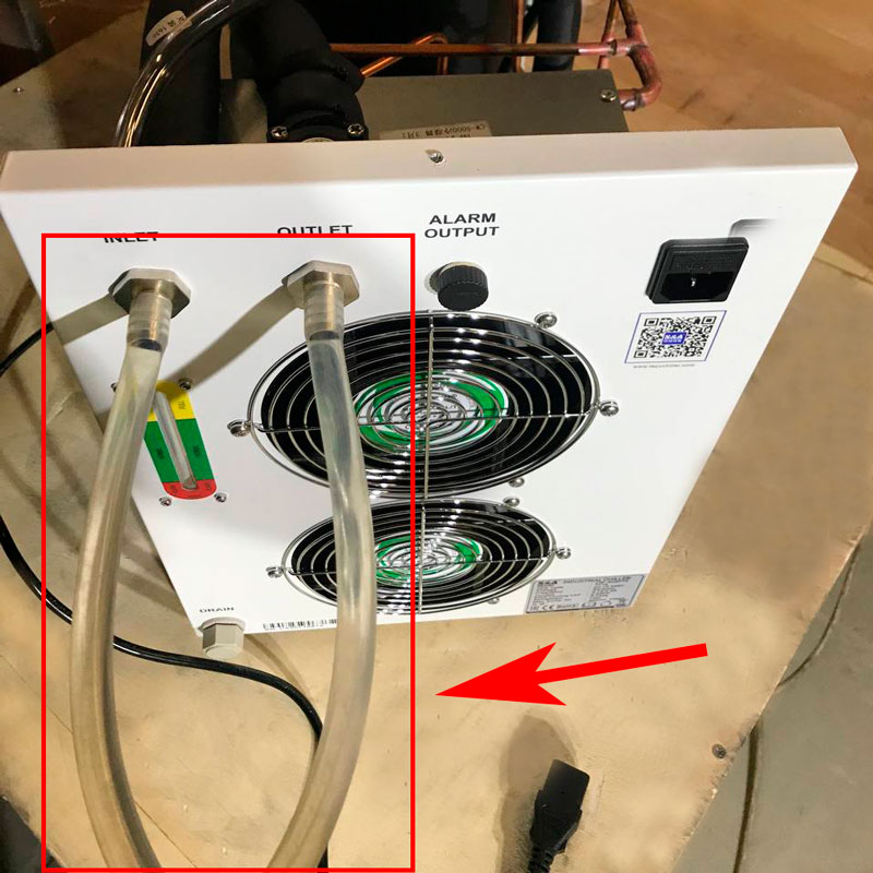
Выключите чиллер, соедините штуцера Inlet и Outlet силиконовым шлангом длиной 1 метр (как на Рис.1), а затем включите чиллер, чтобы проверить работоспособность.
Ситуация 1: водяной контур работает нормально, сигнализация остановлена — мигает зеленый свет.
Причина: шланги (трубки), которые используются для соединения охладителя и лазерного станка, а также силиконовые шланги (трубки), внутри чиллера засорились или перегнулись.
Решение: прочистите шланги (трубки), чтобы устранить засор, или замените погнутые или поврежденные шланги (трубки).
Ситуация 2: водяной контур работает нормально, сигнал тревоги продолжается — мигает красный свет.
Причина:
1. Проблема с датчиком протока воды.
2. Проблема с реле.
Диагностика:
1. Выключите чиллер, затем откройте металлический кожух (крышку) чиллера, найдите датчик потока на выходе воды (хладоносителя) из чиллера.
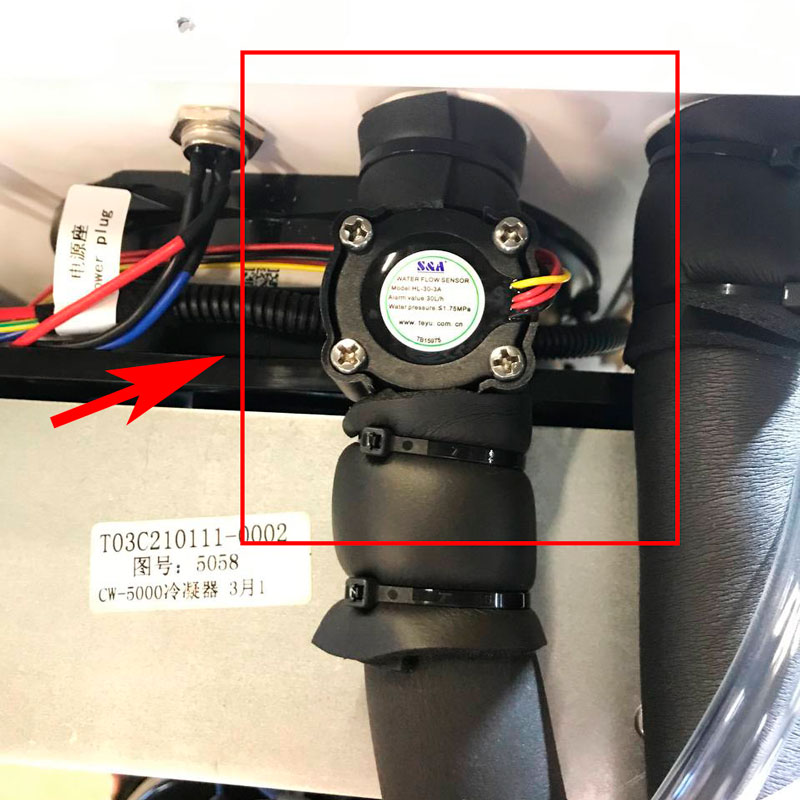
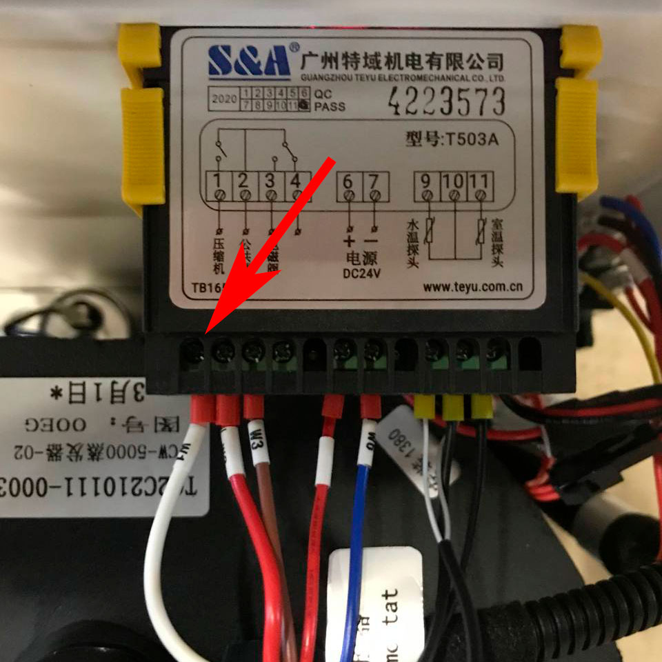
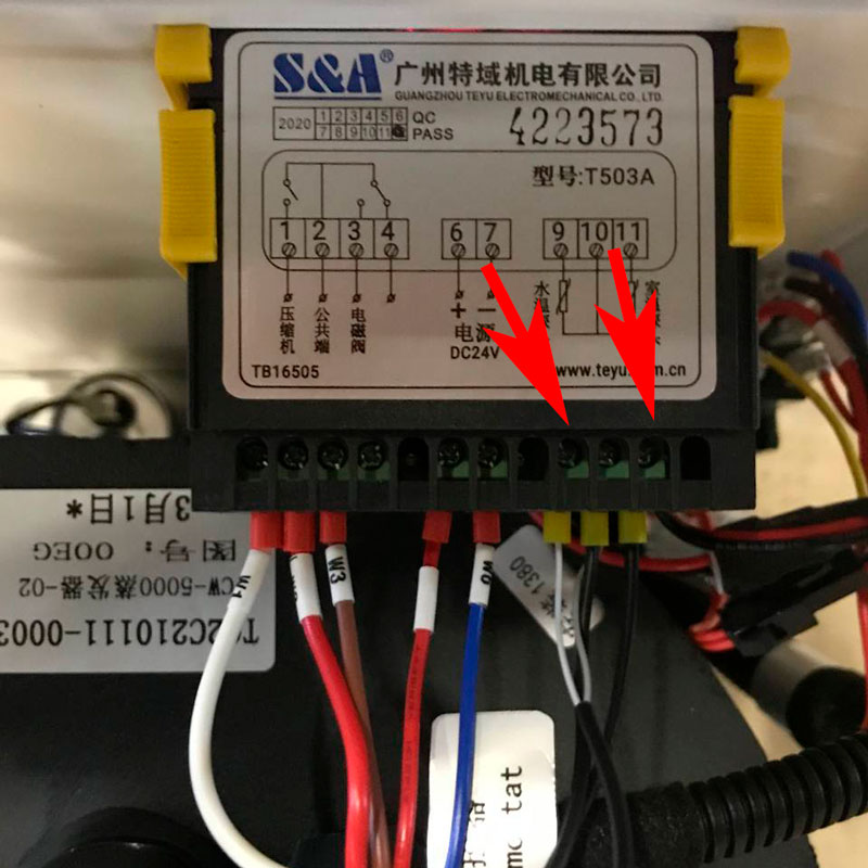
2. Замкните два провода, которые с одной стороны идут к датчику потока воды, а с другой: один подходит к контроллеру чиллера на контакт (-24 V), второй к промежуточному (электромагнитному) реле на контакт (13), желтый провод. Смотрите Рис. 4. Включите чиллер. Если сигнал тревоги прекращается (индикация зеленого сигнала), это говорит о неисправности реле потока.
Решение: замените реле протока воды.
2.2 Если сигнализация тревоги не прекращается (индикация красного сигнала), подсоедините провода в изначальное (заводское) положение для проведения следующего тестирования.
3. Отрежьте четыре провода на Датчике протока, соедините красный провод с другим красным, черный провод соедините с желтым. Затем включите чиллер и посмотрите, продолжится ли сигнализация.
3.1 Если сигнал тревоги прекратится (индикация зеленого сигнала), это можно расценивать как неисправность реле потока.
Решение: замените реле потока.
3.2 Если тревога продолжается, подсоедините эти четыре провода обратно к реле потока для проведения следующего тестирования.
4. Проверьте входное напряжение с помощью контрольно-измерительных приборов.
Примечание: Стандартное напряжение катушки реле переключателя потока дефлектора— AC220V, катушки реле переключателя потока воды —DC24V.
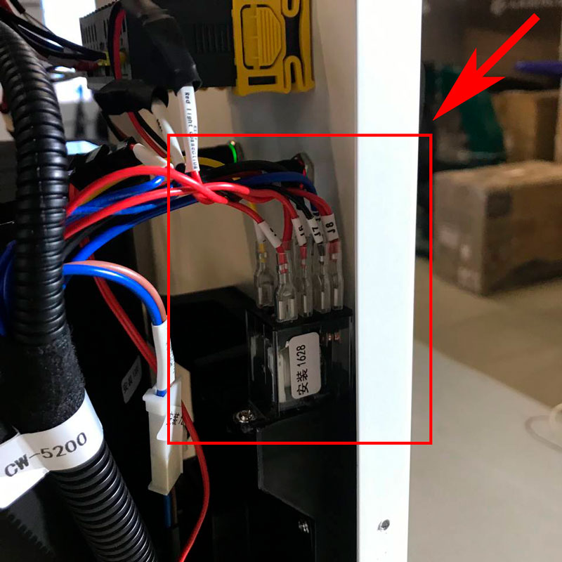
4.1 Если входное напряжение на катушке реле (как на Рис. 4) не соответствует стандартному напряжению, это можно расценивать, как обрыв проводов, которые реле потока (датчик потока) подключается к реле (электромагнитному).
Решение: проверьте, не ослаблены ли провода реле и не сломаны ли они.
Ситуация 3: поток воды включается и выключается, сигнализация продолжается — мигает красный свет.
Причина:
1. Проблема завоздушивания шлангов.
2. Проблема с источниками питания.
3. Проблема с водяным насосом.
Диагностика:
Откройте металлический кожух (крышку) чиллера и проверьте за состояние шлангов (трубок) внутри чиллера.
Прочистите шланги (трубки) для устранения засора или замените погнутые, или поврежденные шланги (трубки).
1. Проверьте выходное напряжение блока питания с помощью специальных инструментов (пр. мультиметр). Стандартное рабочее напряжение блока питания составляет DC24V для машин серии CW-5000.
2. Если выходное напряжение блока питания ниже DC18V, срок службы и расход насоса будут ухудшаться из-за низкого напряжения, это может быть расценено как неисправность блока питания или отказ водяной помпы.
Решение: сначала замените блок питания, а затем протестируйте водяную помпу.
2.2 Если выходное напряжение блока питания составляет DC24, то можно переходить к диагностике водяной помпы
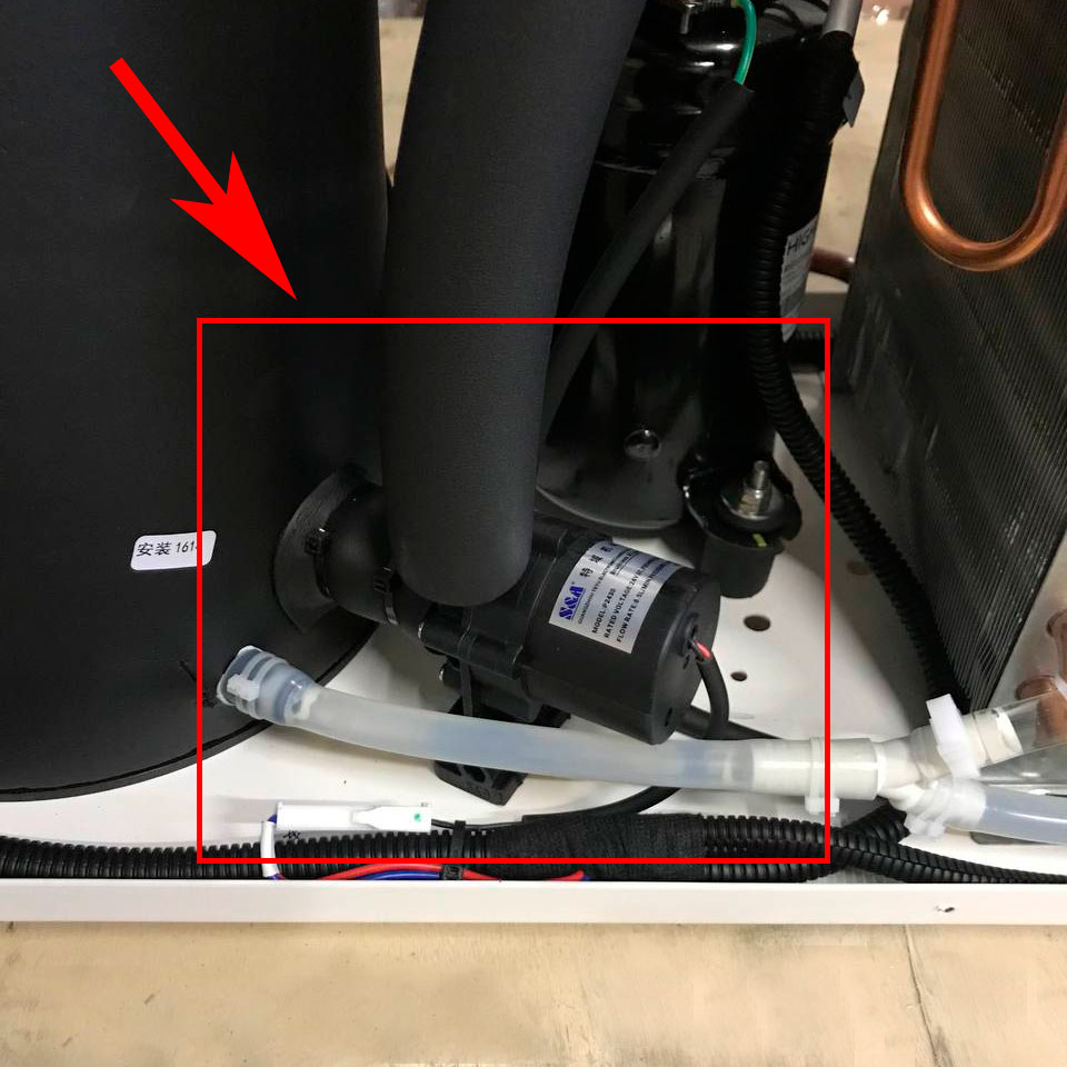
Решение: разберите водяную помпу и проверьте, нет ли завоздушивания или износа ротора. Если тревога продолжается, необходимо заменить водяную помпу.
№2 Сработала сигнализация чиллера — лампочка мигает красным светом. Вода при этом не циркулирует
Причина:
1. Низкий уровень воды
2. Проблема источников питания
3. Проблемы с водяным насосом
Диагностика:
Проверьте уровень воды в чиллере. Уровень воды должен находиться в зеленой области (normal), смотрите Рис. 1.
Решение:
1. Добавьте дистиллированную воду, если уровень воды низкий.
2. Проверьте исправность блока питания с помощью специальных инструментов (пр. мультиметр); стандартное рабочее напряжение импульсных источников питания составляет DC24V для машин серии CW-5000.
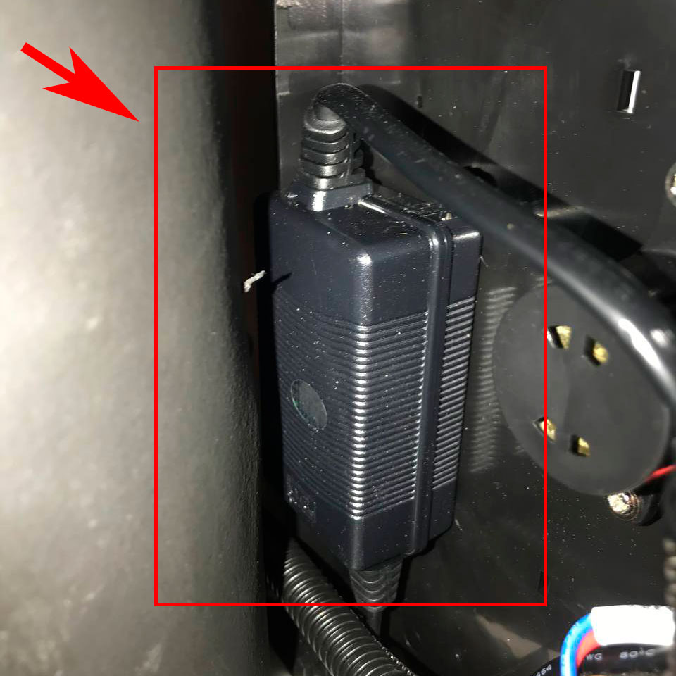
2.1 Если выходное напряжение блока питания ниже DC 18V, срок службы и расход водяной помпы ухудшаются из-за низкого напряжения, это может быть расценено как отказ блока питания или отказ насоса.
Решение: сначала замените блок питания, а затем протестируйте водяную помпу.
3. ЕсливыходноенапряжениеблокапитаниясоставляетDC24v, то можно переходить к диагностике водяной помпы.
Решение: снимите корпус водяной помпы и проверьте, нет ли завоздушивания или износа ротора. Если тревога продолжается, необходимо заменить водяную помпу.
№3 Срабатывает сигнализация, на контроллере CW-5000 серии T-503 отображается код ошибки
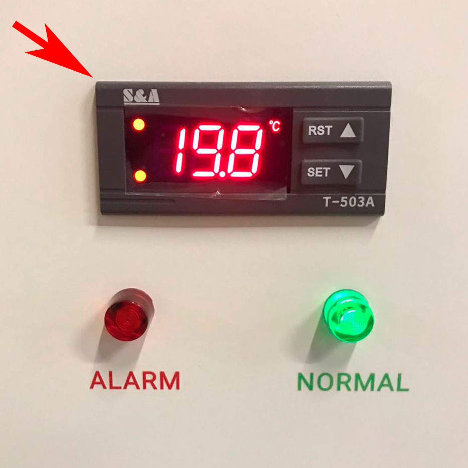
Примечание: в состоянии тревоги звуковой сигнал может быть приостановлен нажатием любой кнопки, но индикация тревоги остается до тех пор, пока ошибка не будет устранена.
По умолчанию при нажатии кнопки ▼ отображается комнатная температура; через 6 секунд восстанавливается отображение температуры воды.
Причина:
1. Температура окружающей среды выше 40℃ или место установки чиллера не проветривается.
Решение: разместить чиллер в вентилируемом месте, для оптимального забора воздуха. Рядом с чиллером должно быть свободное пространство на расстоянии 30 см, а на выходе воздуха из чиллера (где расположен вентилятор) — не менее 50 см.
2. Фильтр на боковых стенках чиллера, запылен.
Решение: необходимо прочистить фильтр чиллера.
3. Большая запыленность конденсатора чиллера.
Решение: необходимо прочистить конденсатор чиллера с помощью компрессора.
Причина:
- Температура окружающей среды выше 40 ℃ или место установки чиллера не проветривается.
- Фильтр на боковых стенках чиллера запылен.
- Большая запыленность конденсатора чиллера.
- Тепловая перегрузка чиллера (тепловая нагрузка выше, чем холодильная мощность чиллера).
- Рабочее напряжение, подаваемое на чиллер, ниже требуемого (уточните требуемое напряжение чиллера вашей модели в паспорте на данную модель чиллера).
- Неисправность вентилятора.
- Неисправность контроллера чиллера.
- Неисправность конденсатора.
- Неисправность компрессора.
- Утечка хладагента.
- Неисправность соленоидного клапана.
- Неисправность компрессора.
1. Проверьте входное напряжение на вентилятор с помощью специальных измерительных приборов (уточните требуемое напряжение чиллера вашей модели в паспорте на данную модель чиллера). При низком уровне напряжения необходимо заменить источник питания чиллера, если входное напряжение отсутствует, то необходимо проверить проводку, которая питает вентилятор чиллера, или это может говорить о неисправности вентилятора.
2. Термостат в состоянии охлаждения. Проверьте рабочее напряжение на выходных клеммах компрессора на задней стороне термостата с помощью специальных измерительных приборов. Если напряжение отсутствует, то это можно считать неисправностью термостата, если напряжение есть, то переходите к следующей части диагностики.
2.2 Проверьте рабочее напряжение на выходных клеммах соленоидного клапана на задней панели термостата с помощью специальных измерительных приборов. Если напряжение на выходе есть, то это можно считать неисправностью термостата, если напряжения нет, то переходите к следующей части диагностики.
3. В состоянии охлаждения компрессор не может запуститься.
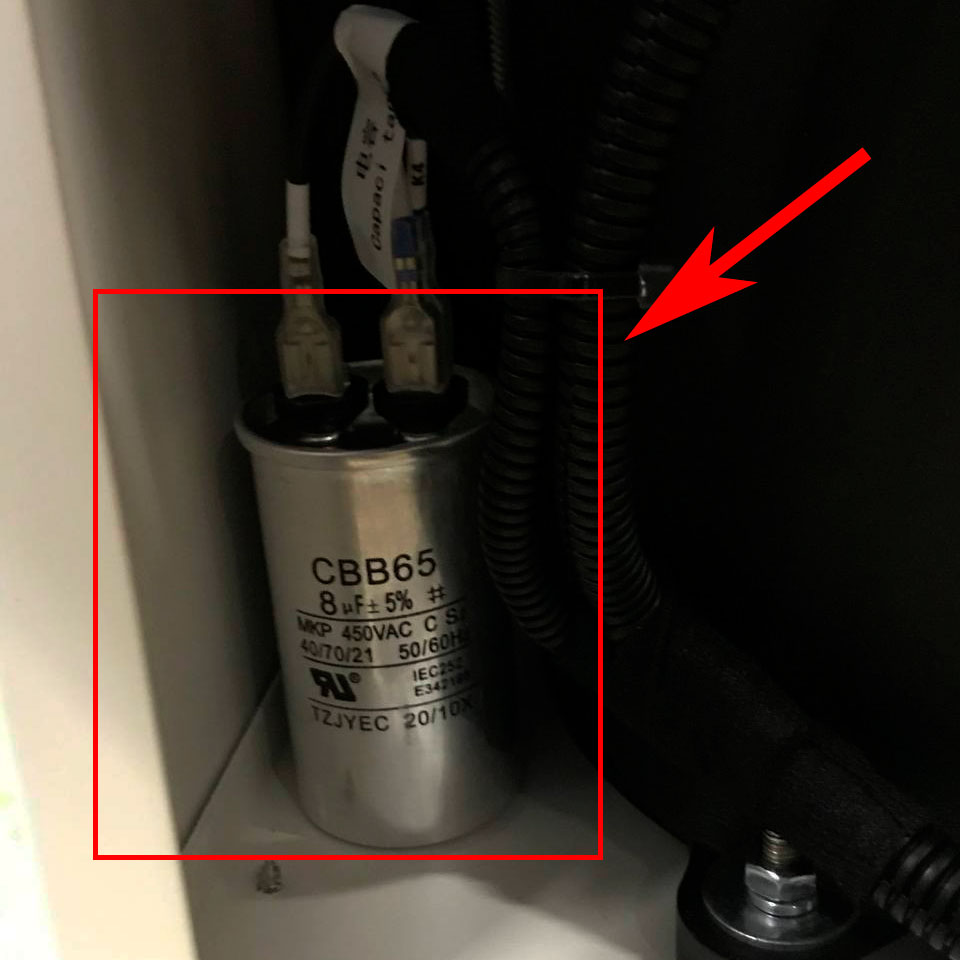
3.1 Проверьте емкость конденсатора компрессора с помощью специальных измерительных приборов, стандартная емкость составляет 10%, если показатель ниже 10%, можно судить о том, что конденсатор компрессора ниже стандартных требований.
3.2 Проверьте входное напряжение компрессора с помощью специальных измерительных приборов (уточните требуемое напряжение чиллера вашей модели в паспорте на данную модель чиллера), если напряжение ниже, чем напряжение компрессора, компрессор неисправен.
3.3 Проверьте выходное напряжение на клемме устройства защиты от перегрузки компрессора с помощью специальных измерительных приборов. Если на выходной клемме нет напряжения, это можно расценить, как отказ защитного фильтра от перегрузки или повреждение цепи.
3.4 Проверьте входной провод (белого цвета) компрессора с помощью амперметра, если ток в три раза или более превышает номинальный ток, это может означать, что ротор компрессора неисправен.
4. Компрессор работает, но не происходит охлаждения хладоносителя.
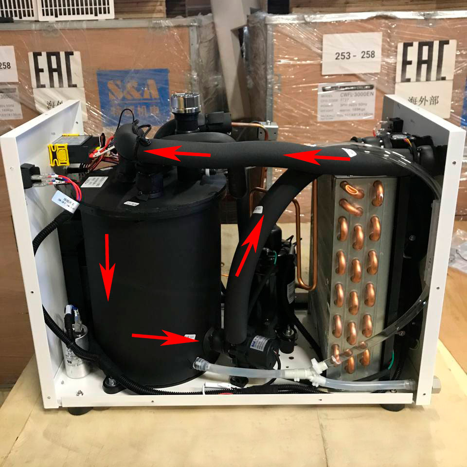
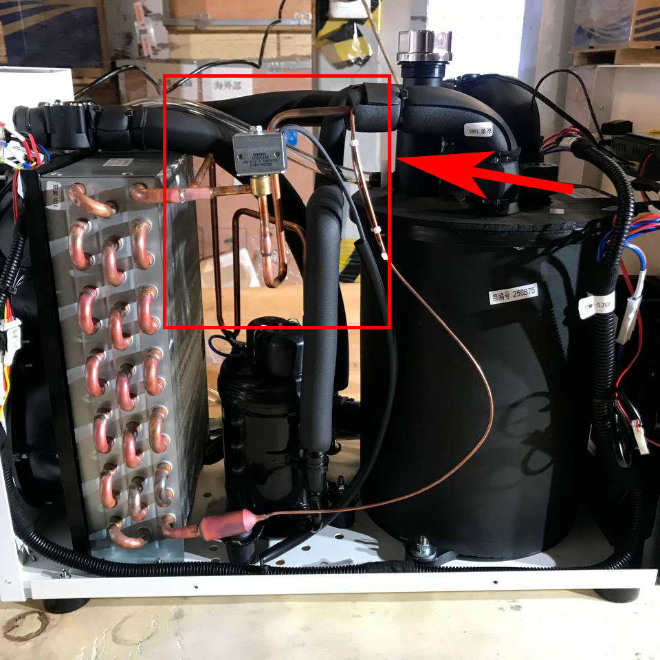
4.1 Осмотрите холодильный трубопровод (как на Рис. 12), нет ли следов масла или инея, таких как явление масла или инея, можно судить об утечке хладагента (например, внутри конденсатора или испарителя, внутренняя трубная линия утечки хладагента).
Решение: поручите нескольким специалистам по обслуживанию кондиционеров найти места утечки, запаять отверстия, а затем заправить хладагент. Объем и марку хладагента можно посмотреть на этикетке чиллера.
4.2 Проверьте емкость конденсатора компрессора с помощью специальных измерительных приборов (как на Рис. 13). Стандартная емкость составляет 10%, если цифра ниже 10%, можно судить о том, что конденсатор компрессора потерял емкость, что приводит к низкой хладопроизводительности.
Решение: замените конденсатор компрессора.
5. Неисправность электромагнитного (соленоидного) клапана (Рис. 14)
6. Ротор компрессора не работает (Рис. 15).
Наблюдайте за вибрацией компрессора, когда термостат достигает состояния охлаждения (загорается D2). Если вибрация компрессора отсутствует, а поверхность компрессора нагревается, это означает, что внутренняя часть компрессора неисправна.
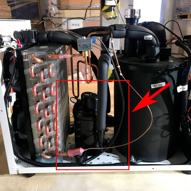
Решение: замените компрессор.
Причина:
Сигнал E3 является нормальным при первом использовании, когда температура окружающей среды низкая (например, зимой и осенью). Просто добавьте немного теплой воды, температура восстановится до рабочей.
Решение: просто добавьте немного теплой воды, температура восстановится до рабочей.
Причина:
1. Неподключенные провода
2. Отказ датчика
Диагностика:
Найдите клеммы датчика температуры окружающей среды и датчика температуры воды (как на Рис.16), поменяйте местами и подключите клеммы датчика температуры окружающей среды и датчика температуры воды к регулятору температуры.
1. Если сигнал тревоги прекращается, можно судить о плохом контакте клемм, затем подключить провода обратно к оригинальным клеммам.
2. Если есть сигнал тревоги E4, можно судить о неисправности регулятора контроллера; если есть сигнал тревоги E5, можно судить о неисправности датчика температуры окружающей среды.
3. Если отображаются коды ошибок E4, E5 одновременно, необходимо заменить датчик температуры окружающей среды и контроллер.
Причина:
1. Разрыв сигнальных проводов.
2. Поломка датчика.
Диагностика:
1. Найдите клеммы датчика температуры окружающей среды и датчика температуры воды (как на Рис. 17), поменяйте местами и подключите датчик температуры окружающей среды и датчик температуры воды к контроллеру.
2. Если сигнализация прекратилась, можно судить о плохом контакте клемм, подсоедините провода к исходным клеммам.
3. Если есть сигнализация ошибки E5, можно судить о неисправности регулятора температуры, если есть сигнализация ошибки E4, можно судить о неисправности датчика температуры.
4. Если сигнализация ошибок E4 и E5 сработали одновременно, необходимо заменить датчик температуры окружающей среды, датчик температуры воды и контроллер.
№4 Чиллер не работает при включении питания
Причина:
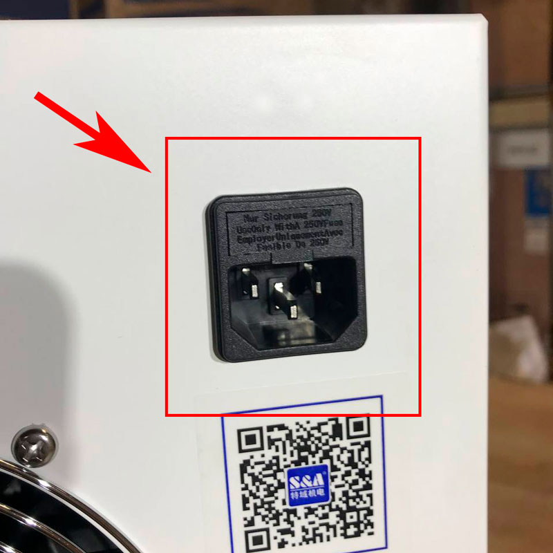
1. Поломка предохранителя.
2. Источники питания с переключаемым режимом работы (220V).
Метод тестирования:
1. Откройте защитную крышку и проверьте, не перегорел ли предохранитель (как на Рис. 18). Если перегорел, замените.
2. Проверьте напряжение AC220V (зависит от режима работы машины), если напряжение не поступает. Необходимо устранить неполадку сети питания.
Ошибка E02 в стиральной машине Candy
Опубликовано: 14 Мар 2020

Е02 — одна из распространенных ошибок стиральных машин Канди. Она проявляется следующим образом:
- стиральная машина не заливает воду и показывает ошибку на дисплее (по статистике, это самый распространенный симптом);
- вода набирается очень долго, затем машина высвечивает ошибку Е02;
- машинка переливает воду (то есть набирает больше, чем нужно для стирки), затем включается слив и загорается код на экране;
- машина стирает, но постоянно добирает воду, а затем «уходит» в ошибку, Код появляется на этапе стирки или во время полоскания, причем это может происходить не каждый раз, а периодически.
Расшифровка ошибки
Код E02 на экране СМА Канди указывает на неполадки с набором воды. Причём могут возникнуть две кардинально разные проблемы: первая — трудности с набором нужного количества воды, вторая — перелив воды выше допустимого уровня.
Примечание! Стиральная машина Канди также может отображать Е02 с помощью кодов E2, Error 2 или Err 2. Это одна и та же ошибка.
Примерно треть неполадок с ошибкой E02 владельцы Candy могут исправить без приглашения мастера. На самом деле это даже не поломки, а несоблюдение правил установки и эксплуатации стиральной машины.
Самослив воды из бака

Недавно установленная машина во время стирки или полоскания постоянно добирает воду. Вероятно, некорректно подключён слив машинки: сливной шланг полностью располагается ниже уровня бака, поэтому вода самопроизвольно вытекает в канализацию.
Необходимо установить стиральную машину Канди согласно инструкции производителя. Сливной шланг должен делать петлю выше уровня бака, прежде чем войти в канализацию.
Не подается вода

Возможно, подача воды в стиральную машину Candy перекрыта или вовсе отсутствует в водопроводе. Проверьте, что запорный вентиль подачи воды открыт. Если вода в кране отсутствует вовсе, обратитесь в управляющую компанию.
Слабый напор воды

Когда машина тратит много времени на наполнение бака, а потом пишет код Е02 на дисплее, вероятно, не до конца открыт запорный вентиль, который перекрывает подачу воды в машину. Ещё одна причина слабого напора — низкое давление в водопроводе. В первом случае откройте вентиль полностью. Во-втором — обратитесь в управляющую компанию.
Засор фильтра перед впускным клапаном

Засорение сеточки также приводит к медленному набору воды. Сетчатый фильтр фильтрует воду, поступающую в машину. На нём откладывается накипь, металлические окислы и другие примеси. Перекройте подачу воды в машину, открутите заливной шланг и достаньте фильтр с помощью плоскогубцев. Промойте его под струёй воды и поместите в раствор лимонной кислоты на 30-60 минут для очистки.
Вероятные поломки, когда без профессионального ремонта не обойтись
Ошибка E02 может указывает не только на незначительные неполадки, но и на серьезные поломки, которые требуют вмешательства мастера. Вот возможные неисправности, которые требуют ремонта.
Заливной клапан — от 1500 руб*
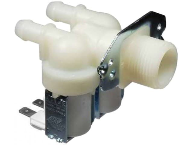
Самая распространённая поломка Candy при ошибке Е02. Она встречается примерно в 70% случаев. В устройство клапана подачи воды входит корпус, мембрана и электромагнитная катушка. Старые модели Канди оснащены клапанами одинарного типа, в современных машинках используют двухсекционные клапаны: одна секция отвечает за набор воды, необходимой для стирки, через вторую секцию в бак поступает вода на этапе полоскания.
Ремонту клапан не подлежит, требуется — его замена.
Блок управления — от 1900 руб*
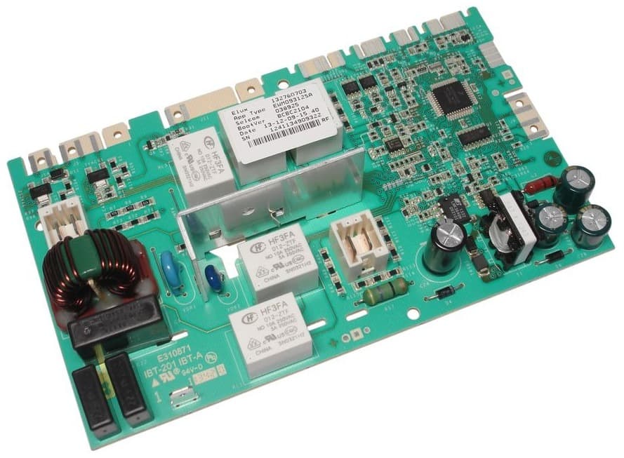
Происходит сбой «прошивки» или выходят из строя элементы платы в цепи управления заливным клапаном. Обычно неисправность возникает сразу после включения стирки, иногда — в процессе стирки или на полоскании.
Если дело в «прошивке», достаточно перепрограммировать память блока управления. Если при диагностике мастер выявит дефекты платы, нужно перепаять неисправные элементы, пропаять дорожки и контакты. В некоторых случаях восстановить модуль не удается, поэтому требуется замена платы управления.
Датчик уровня воды (прессостат) — от 1600 руб*
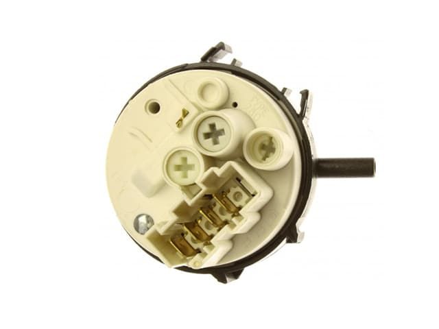
Основная задача датчика или реле уровня воды — определение уровня наполнения бака. При неисправном прессостате вода:
- не набирается вообще,
- набирается и сразу сливается,
- набирается слишком много воды.
Поломка возникает из-за засорения камеры отбора давления, повреждения трубки прессостата или выхода из строя самого датчика.
Вариант устранения поломки выбирается только после диагностики. Основные способы: снятие и очистка камеры отбора давления, проверка шланга прессостата и замены его на новый. При выходе из строя датчика, прессостат меняется полностью.
Проводка или контакты в цепи клапана подачи воды — от 1500 руб*

Поломка возникает по причине механического повреждения проводки и обрыва сигнала, подающегося на заливной клапан. Провода перетираются из-за вибраций при отжиме. В частных домах вред наносят грызуны.
Поврежденные провода восстанавливаются или меняется весь шлейф с проводами. Прогоревшие или сгнившие контакты пропаиваются или меняются на новую контактную группу.
*Стоимость ремонта складывается из двух компонентов: суммы за услуги мастера и цены новых комплектующих. Детали используются новые и оригинальные, на каждую запчасть дается гарантия.
Обращение в компанию «Вош Мэн» — правильное решение
Заметили на дисплее стиральной машины Канди ошибку E02? Попробовали справиться с проблемой самостоятельно, но результатов это не дало? Позвоните в компанию «Вош Мэн». Мастер прибудет по вашему адресу не позднее, чем через 24 часа после оформления заявки или в указанное вами время. Мы не только отремонтируем стиральную машину Candy, но и дадим гарантию до 2 лет на работу и установленные запчасти.
![]()
![]()
![]()
![]()
Дата материала: 25.04.2022

Код ошибки E02 котла BAXI означает, что разомкнуты контакты предохранительного термостата перегрева.Термостат перегрева и датчик температуры теплоносителя, как правило, располагается на выходной трубе первичного теплообменника, основная функция – защита котла от критического повышения температуры и в случае срабатывания прекращается подача газа на горелку, котел останавливается.
Предохранительный термостат — это датчик, у которого состояние контактов нормально замкнутое. В случае, если температура на термостате достигает значения более 99 градусов, то контакты размыкаются и котел блокируется с ошибкой Е02.
Ошибку можно сбросить кнопкой, но если состояние датчика не изменилось, то при очередном запросе на отопление или ГВС ошибка Е02 появится снова еще до розжига горелки.
В состояние нормально замкнутых контактов датчик переходит, если температура опустилась ниже 94 градусов.
Вероятная причина возникновения ошибки е02 на котле baxi может быть связана с работой самого термостата, датчика температуры теплоносителя и следствием нарушения работы основного циркуляционного контура котла:
- засорен первичный теплообменник или фильтра контура отопления (недостаточная циркуляция – повышенный нагрев теплоносителя)
- неисправен термостат перегрева (плохой контакт термостата с платой управления)
- неисправен циркуляционный насос (отсутствие правильной циркуляции), наличие воздушной пробки в системе отопления
Некоторые действия по проверке владелец котла может осуществить самостоятельно, для запуска котла нужно удерживать кнопку R примерно 2-3 секунды. Почему-то иногда у BAXI пользователи испытывают затруднение со сбросом ошибки. Она должна сбрасываться — проверял на своем котле.
Итак, рассмотрим самые распространенные причины и методы их диагностики.

Проверка термостата перегрева (BAXI E02)
Как уже было сказано ранее контакты датчика должны быть замкнуты, если температура не выше 99 градусов. Поэтому, необходимо подождать 15-20 минут, пока котел остынет, затем с помощью тестера проверить состояние контактов датчика.
Не путать термостат с датчиком температуры, который находится рядом (ниже по трубе). Термостат располагается вверху, сразу на выходе из теплообменника.
Если проверка показала, что контакты разомкнуты на остывшем котле, то датчик необходимо заменить.

На практике, возникновение ошибки e02 на бакси наиболее часто связано с неисправностью датчика или засоренностью теплообменника.
Ошибка Е02 — фактический перегрев котла
Если с датчиком всё в порядке, то вероятнее всего теплоноситель всё же достигает критических температурных значений и необходимо выяснить причину. Причина перегрева — отсутствие циркуляции теплоносителя. Это в свою очередь может быть вызвано абсолютно различными факторами: не работает циркуляционный насос, очень слабый проток воды через теплообменник. По этому поводу лучше изучить другие материалы:
Котел быстро набирает температуру
Если ошибка Е02 появляется исключительно при использовании котла в режиме приготовления горячей воды, то это может быть связано с низким протоком водопроводной воды через теплообменник в совокупности с неправильно настроенным газовым клапаном. Такой случай из практики я подробно описывал здесь:
Перегрев BAXI в режиме ГВС (ошибка E02)
С другими причинами, которые могут быть связаны с такой ошибкой я не встречался. Один раз была в ремонте плата управления, которая постоянно показывала ошибку Е02 независимо от состояния датчика — но это было следствие неквалифицированного вмешательства в схему.
Возможно, будет интересно:
Экономичный режим работы котла с комнатным термостатом
Настройка мощности газового котла
Какую температуру выставлять на газовом котле?
Почему падает давление в газовом котле

Рекомендуемые сообщения
-
#1
где найти таблицу кодов ошибок для фрониус ВариоСинержик 5000 и если кто знает какие основные болячки у этого аппарата бывают
Поделиться сообщением
Ссылка на сообщение
-
#2
Что интересует конкретно?? Какие то проблемы??
Поделиться сообщением
Ссылка на сообщение
-
#3
проблема в следуюшем на работе стоит трактор фрониус документов к нему нет вообще переодичеки выдаёт ошибку е42 приходится всё исправлять методом тыка что очень неудобно, хотелось бы найти документы к нему и ели кто сталкивался с таким аппаратом что у него чаще бывают за проблемы т.е. куда сразу стоит обратить внимание.
Поделиться сообщением
Ссылка на сообщение
-
#4
E42 КЗ во вторичных цепях, возможные проблемы горелка или силовые провода.
Изменено 04.03.2012 10:16 пользователем s_even
Поделиться сообщением
Ссылка на сообщение
-
#5

Поделиться сообщением
Ссылка на сообщение
-
#6
Добрый день! Аппарат фрониус 320ТСР, постоянно выдает ошибку 9649, варим АМг5
Поделиться сообщением
Ссылка на сообщение
Для публикации сообщений создайте учётную запись или авторизуйтесь
Вы должны быть пользователем, чтобы оставить комментарий
Войти
Уже есть аккаунт? Войти в систему.
Войти
-
Последние посетители
0 пользователей онлайн
Ни одного зарегистрированного пользователя не просматривает данную страницу
One of the most popular inverter brands for solar in Australia is the Fronius Inverters range. With a range of inverters from 1.5 to 27kW there’s guaranteed to be suitable inverter for virtually any solar system size from residential to large scale industrial.
Fallon Solutions have extensive experience with solar inverters and we realise not everything is perfect all the time. Here you can find a list is a list of common Fronius inverter Error Codes with potential errors and solutions to fix them.
Fronius IG Inverter
Fronius IG STATE codes beginning with 1xx
Fronius STATE codes beginning with 1 usually only occur temporarily and are caused by the power from the electrical mains (grid) being outside the inverters operating parameters.
| Code | Description | Possible causes | Remedy (sequence) |
| STATE 101 | Grid voltage beyond permitted limits | 1. Mains voltage error
2. Incorrect values in the service menu 3. Internal fault |
1. Check grid voltage, check circuit breakers are ON
2. Change values in the service menu 3. If problem persists contact your Fronius Service Partner |
| STATE 104 | Mains frequency beyond permitted limits. | 1. Mains frequency error
2. Incorrect values in the service menu 3. Internal fault |
1. Check mains frequency, check circuit breakers are ON
2. Change values in the service menu 3. If problem persists contact your Fronius Service Partner |
| STATE 107 | Synchronisation with the public mains supply not possible | 1. Mains not connected
2. Incorrect values in the service menu 3. Internal fault |
1. Connect mains power, check circuit breakers are ON
2. Check values in the service menu 3. If problem persists contact your Fronius Service Partner |
| STATE 108 | Islanding detected | 1. Islanding detected
2. Severe disturbances in public mains 3. Internal fault |
1. Automatic correction
2. Automatic correction 3. If problem persists contact your Fronius Service Partner |

Fronius IG STATE codes beginning with 2xx
Fronius IG STATE codes beginning with 2 are messages from the grid monitoring device (ENS) integrated within the inverter and refer to the parameters of the public mains.
| Code | Description | Possible causes | Remedy (sequence) |
| STATE 101 | Grid voltage beyond permitted limits | 1. Mains voltage error
2. Incorrect values in the service menu 3. Internal fault |
1. Check grid voltage, check circuit breakers are ON
2. Change values in the service menu 3. If problem persists contact your Fronius Service Partner |
| STATE 104 | Mains frequency beyond permitted limits. | 1. Mains frequency error
2. Incorrect values in the service menu 3. Internal fault |
1. Check mains frequency, check circuit breakers are ON
2. Change values in the service menu 3. If problem persists contact your Fronius Service Partner |
| STATE 107 | Synchronisation with the public mains supply not possible | 1. Mains not connected
2. Incorrect values in the service menu 3. Internal fault |
1. Connect mains power, check circuit breakers are ON
2. Check values in the service menu 3. If problem persists contact your Fronius Service Partner |
| STATE 108 | Islanding detected | 1. Islanding detected
2. Severe disturbances in public mains 3. Internal fault |
1. Automatic correction
2. Automatic correction 3. If problem persists contact your Fronius Service Partner |
Fronius IG STATE codes beginning with 3xx
Fronius IG STATE codes beginning with 3 are error states that can occur during grid feed-in operation, however, they do not indicate damaged electronics and do not lead to a remaining interruption of the feed-in operation.
| Code | Description | Possible causes | Remedy (sequence) |
| STATE 301 | Safety circuit detects a current peak on the mains supply. | 1. Voltage drop on the public mains
2. Internal fault |
1. Automatic correction
2. If problem persists contact your Fronius Service Partner |
| STATE 302 | Safety circuit detects a current peak on the PV generator side | 1. Voltage drop on the public mains supply
2. Internal fault |
1. Automatic correction
2. If problem persists contact your Fronius Service Partner |
| STATE 303 | Heat sink temperature on the DC-AC board is too high | 1. Ventilation slot congested
2. Very high ambient temperature 3. Distance between inverters too small 4. Internal fault |
1. Free ventilation slot
2. Change location of inverter 3. Increase distance between inverters 4. If problem persists contact your Fronius Service Partner |
| STATE 304 | Heat sink temperature on the DC-DC board is too high | ||
| STATE 305 | Feed-in process not possible, even though public mains parameter within the limits | Internal fault | If problem persists contact your Fronius Service Partner |
| STATE 306 | POWER LOW | Intermediate circuit voltage has dropped below permissible threshold value for feed in. | 1. Check panels
2. Internal fault |
| STATE 307 | DC LOW | 1. DC-input voltage is too low for feed in
2. Internal fault |
|
| STATE 308 | Intermediate circuit voltage out of the maximum limit | 1. Public mains disturbances
2. Internal fault |
1. Reinforce mains cable
2. If problem persists contact your Fronius Service Partner |
Fronius IG STATE codes beginning with 4xx
Fronius IG STATE codes beginning with 4 are error states that require the intervention of a Fronius Service Partner. They are either temporary or lasting and are triggered by faulty hardware or a software problem.
| Code | Description | Possible causes | Remedy (sequence) |
| STATE 401 | Communication error between IG control and the DC-DC board | Internal fault | If problem persists contact your Fronius Service Partner |
| STATE 402 | Write access to the internal Fronius IG memory failed | ||
| STATE 403 | The area in the internal memory for the country setting is incomplete | ||
| STATE 404 | Connection between the control unit and the ENS is faulty | 1. Public mains not connected
2. Internal fault |
1. Check the public mains
2.If problem persists contact your Fronius Service Partner |
| STATE 405 | An old or incorrect version of the ENS microprocessors has been recognised | Internal fault | If problem persists contact your Fronius Service Partner |
| STATE 406 | Temperature sensor on the DC-AC board faulty or not connected | ||
| STATE 407 | Temperature sensor on the DC-DC board faulty or not connected | ||
| STATE 408 | Unsymmetry on the public mains detected | 1. Public mains disturbances
2. Internal fault |
1. Error is remedied automatically
2. If problem persists contact your Fronius Service Partner |
| STATE 409 | Supply of the DC-AC board not available | Internal fault | If problem persists contact your Fronius Service Partner |
| STATE 410 | Service plug on the DC-AC board is not set correctly | ||
| STATE 412 | Value for fixed voltage is set higher than the open circuit voltage of the PV generator | ||
| STATE 413 | Open circuit voltage too high in the moment of transformer switching | ||
| STATE 414 | Memory array for Fronius IG type in EE-PROM faulty | 1. One-off – memory error
2. Internal fault |
1. Error is remedied automatically
2. If problem persists contact your Fronius Service Partner |
| STATE 415 | No END-enabling signal despite release by IG-control | Internal fault | If problem persists contact your Fronius Service Partner |
| STATE 416 | Communication error between IG-Control and power stack | 1. One-off – communication error
2. Internal fault |
1. Error is remedied automatically
2. If problem persists contact your Fronius Service Partner |
| STATE 417 | Hardware ID-collision | Internal fault | If problem persists contact your Fronius Service Partner |
| STATE 419 | Two or more power stacks with identical Unique ID | ||
| STATE 420 | Incomplete number of power stacks detected after reaching online threshold according to device type | ||
| STATE 421 | Hardware ID sequence error | ||
| STATE 425 | Receive time-out for data exchange with one or more power stacks exceeded | 1. One off error
2. Internal fault |
1. Automatic correction
2.If problem persists contact your Fronius Service Partner |
| STATE 431 | All power stacks are in boot mode | Internal fault | If problem persists contact your Fronius Service Partner |
| STATE 432 | Consistent error in power stack management | 1. One off error
2. Internal fault |
1. Automatic correction
2.If problem persists contact your Fronius Service Partner |
| STATE 433 | Allocation error of dynamic addresses | ||
| STATE 434 | Ground fault detected | ||
| STATE 435 | Wrong configuration for EE-Prom | ||
| STATE 436 | Error transmission faulty | ||
| STATE 437 | Power stack work around is active | ||
| STATE 438 | Error during state code transmission | 1. One-off error
2. Permanent error |
1. Automatic correction
2.If problem persists contact your Fronius Service Partner |
| STATE 441 | Power rack fan faulty | Internal fault | If problem persists contact your Fronius Service Partner |
| STATE 442 | Master for one phase could not be assigned | 1. Temporary communication error
2. Internal fault |
1. Error is remedied automatically
2. If problem persists contact your Fronius Service Partner |
| STATE 443 | DC-DC energy transfer failure. | 1. Error during switching on a power stack
2. Internal fault |
1. Error is remedied automatically
2. If problem persists contact your Fronius Service Partner |
| STATE 444 | AC monitoring self test interrupted | During the self test another error occurred | Quit the self test by pressing ESC and remedy the failure according to the error code list |
Fronius IG STATE codes beginning with 5xx
Fronius IG STATE codes beginning with 5 generally do not stop the feed-in operation of the Fronius IG inverter. The STATE codes will be displayed until the message is acknowledged by pushing a button on the display (the inverter will work in feed-in operation during this time).
| STATE 501 | Heat sink temperature too high, although Fronius IG is on low output | 1. Ventilation slot congested
2. Internal fault |
1. Free ventilation slot
2.If problem persists contact your Fronius Service Partner |
| STATE 502 | An isolation fault between DC+ or DC- to earth has been detected | Isolation fault at the solar generator | Check cables and solar generator |
| STATE 504 | An error occured while scanning LocalNet addresses | Identical Fronius IG address used twice | Check address of the inverters and other components |
| STATE 505 | The area in the internal memory for the “Setup” values is incomplete | 1. One off error
2. Internal fault |
1. Automatic correction
2.If problem persists contact your Fronius Service Partner |
| STATE 506 | The area in the internal memory for the “Total” values is incomplete | ||
| STATE 507 | The area in the internal memory for the “Day/Year” values is incomplete | ||
| STATE 508 | The area in the internal memory for the “WR number” is damaged | ||
| STATE 509 | No feed in operation for 24 hours | 1. Snow covered or very dirty solar panels
2. Insufficient power from the solar panels for feed in operation 3.Internal error |
1. Clean solar panels or remove snow
2. If problem persists contact your Fronius Service Partner |
| STATE 510 | Errors detected by LocalNet self diagnostic system | 1. One-off memory error
2. Internal fault |
1. Automatic correction
2. If problem persists contact your Fronius Service Partner |
| STATE 511 | Errors detected by LocalNet Sensor Card self diagnostic system | ||
| STATE 512 | According to the device type too many power stacks have been detected | 1. One-off error
2. Internal fault |
|
| STATE 513 | Power stacks in boot mode | ||
| STATE 514 | Incomplete number of power stacks detected after reaching online threshold – Device type | ||
| STATE 515 | One or more power stacks notified STATE 406/ 407/ 409/ 410 | Internal fault | If problem persists contact your Fronius Service Partner |
FRONIUS GALVO COMMON ERRORS
Fronius Galvo STATE codes beginning with 1xx
Fronius STATE codes beginning with 1 usually only occur momentarily and are caused by the power from the street (the grid) being outside the inverters operating parameters.
| Code | Description | Behaviour | Remedy |
| STATE 102 | AC voltage too high | Following careful testing and when the grid conditions are within the permissible range again, the inverter will resume feeding energy into the grid. | Check grid connections: If this STATE code keeps recurring contact your solar power system installer. |
| STATE 103 | AC voltage too low | ||
| STATE 105 | AC frequency too high | ||
| STATE 106 | AC frequency too low | ||
| STATE 107 | AC grid outside the permissible limits | ||
| STATE 108 | Stand alone operation detected |
Fronius Galvo STATE codes beginning with 3xx
Fronius Galvo STATE codes beginning with 3 are status codes that may occur while feeding energy into the grid, but generally do not cause the process to be interrupted for any length of time. The inverter disconnects automatically from the grid, the grid is then monitored as specified and the inverter attempts to resume feeding energy into the grid.
| Code | Description | Behaviour | Remedy |
| STATE 301 | Overcurrent (AC) | Short-term interruption while feeding energy into the grid due to over current in the inverter.
The inverter resumes with its startup routine. |
Fault is rectified automatically; if this STATE code is displayed all the time: notify your local Fronius service partner. |
| STATE 302 | Safety circuit detects a current peak on the PV generator side | ||
| STATE 303 | Power stage set over temperature | Short term interruption while feeding energy into the grid due to over temperature.
The inverter resumes with its startup routine. |
Purge openings for cooling air and heat sink if necessary; fault is rectified automatically; if this STATE code keeps recurring contact your solar power system installer. |
| STATE 304 | Internal temperature too high | ||
| STATE 306 | LOW PV OUTPUT
Intermediate circuit voltage too low for feeding energy into the grid |
Short term interruption while feeding energy into the grid.
The inverter resumes with its startup routine. |
Fault is rectified automatically; if this STATE code occurs when there is sufficient insolation (sunlight) contact your solar power system installer.
IMPORTANT! Due to the low level of insolation (sunlight) early in the morning and in the evening, the STATE codes 306 (LOW PV OUTPUT) and 307 LOW PV VOLTAGE) are displayed routinely at these times of day. These STATE codes do not indicate any kind of fault. |
| STATE 307 | LOW PV VOLTAGE
DC input voltage too low for feeding energy into the grid |
||
| STATE 308 | Intermediate circuit overvoltage | Short term interruption while feeding energy into the grid. The inverter resumes with its startup routine. | Fault is rectified automatically; if this STATE code is displayed all the time: notify your local Fronius service partner. |
| STATE 309 | DC input voltage too high |
Fronius Galvo STATE codes beginning with 4xx
Fronius STATE codes beginning with 4 are error states that require the intervention of a Fronius Service Partner. They are either temporary or lasting and are triggered by faulty hardware or a software problem.
| Code | Description | Behaviour | Remedy |
| STATE 401 | No communication with power stage set possible | The inverter will automatically attempt to connect again and, if possible, will resume feeding energy into the grid. | If the STATE code is displayed all the time contact your local Fronius Service Partner |
| STATE 406 | Power stage set temperature sensor faulty | ||
| STATE 407 | Internal temperature sensor faulty | ||
| STATE 408 | DC feeding into the grid detected | ||
| STATE 412 | Fixed voltage mode has been selected instead of MPP voltage mode and the fixed voltage has been set to too low or too high a value | – | If this STATE code persists contact your solar power system installer |
| STATE 415 | Safety cut out via option card or RECERBO has triggered | The inverter is not feeding any energy into the grid. | If the STATE code is displayed all the time contact your local Fronius Service Partner |
| STATE 416 | No communication possible between power stage set and control system | The inverter will automatically attempt to reconnect again and, if possible, will resume feeding energy into the grid. | |
| STATE 425 | No communication possible with the power stage set | ||
| STATE 445 | Invalid limit value settings | The inverter is not feeding any energy into the grid for safety reasons. | Update the inverter firmware with the latest firmware here ; if the STATE code is displayed all the time after the firmware update contact your local Fronius Service Partner. |
| STATE 452 | Communication error between the processors | The inverter will automatically attempt to connect again, and if possible, will resume feeding energy into the grid. | If the STATE code is displayed all the time: notify your local Fronius Service Partner. |
| STATE 453 | Short term grid voltage error | ||
| STATE 454 | Short term grid frequency error | ||
| STATE 457 | Grid relay sticking | The inverter is not feeding any energy into the grid. | Contact your local Fronius Service Partner. |
| STATE 459 | Error when recording the measuring signal for the insulation test | ||
| STATE 460 | Reference voltage source for the digital signal processor (DSP) is working out of tolerance | ||
| STATE 472 | Fuse for solar panel ground is faulty | Replace fuse for solar panel ground; if this STATE code keeps recurring contact your solar power system installer. | |
| STATE 475 | Solar panel ground, insulation fault (connection between solar panel and ground) | If this STATE code keeps recurring, contact your solar power system installer | |
| STATE 482 | Startup incomplete | Perform AC reset (turn AC circuit breaker off and on), complete startup. |
Fronius Galvo STATE codes beginning with 5xx
Fronius STATE codes beginning with 5 generally do not stop the feed in operation of the Fronius Galvo inverter. The STATE codes will be displayed until the message is acknowledged by pushing a button on the display (the inverter will work in feed in operation during this time).
| Code | Description | Behaviour | Remedy |
| STATE 502 | Insulation error on the solar panels | Warning message is shown on the display | If this STATE code keeps recurring, contact your solar power system installer. |
| STATE 509 | No energy fed into the grid in the past 24 hours | It is normal to see the state 509 code when the inverter has just been installed.Acknowledge STATE code; check whether all the conditions for the problem free feeding of energy into the grid have been met. If the STATE code is displayed all the time: look out for further STATE codes. | |
| STATE 516 | Firmware fault | Firmware fault with the inverter, firmware update required. | Update the inverter firmware; if the STATE code is displayed all the time after the firmware update contact your local Fronius Service Partner. |
| STATE 517 | Derating caused by too high a temperature | When power derating occurs, a warning message is shown on the display | Purge cooling air openings and heat sink if necessary; fault is rectified automatically; if this STATE code keeps recurring contact your solar power system installer. |
| STATE 551 | Fuse for solar panel ground is faulty | Warning is shown on display | Replace fuse for solar panel ground; if this STATE code keeps recurring contact your solar power system installer. |
| STATE 558 | Functional incompatibility (one or more PC boards in the inverter are not compatible with each other, e.g. after a PC board has been replaced) | Possible error displays or malfunction on the inverter | If this STATE code keeps recurring contact your solar power system installer. |
| STATE 560 | Derating caused by over-frequency | This STATE code is displayed when the grid frequency becomes excessively high. The inverter will then reduce its output. The status indicator will continue to be displayed until the inverter has returned to normal operation. | As soon as the grid frequency is back within the permissible range and the inverter has returned to normal operation, the fault is rectified automatically. If this STATE code keep recurring contact your solar power system installer. |
| STATE 567 | Grid Voltage Dependent Power Reduction is active | This state code is a warning informing you that the Grid Voltage Dependent Power Reduction mode (GVDPR or Volt – Watt mode) has been activated and the inverter will continue to operate with reduced power output. This is because the grid voltage has exceeded 250Vac and the GVDPR has been enabled to try to reduce the voltage rise at the inverters terminals. This mode must be enabled by default in accordance with the latest Australian Standards. | Acknowledge status code; if the STATE 567 code keeps recurring contact your local solar power system installer. |
| STATE 568 | Incorrect input signal on the multifunction current interface | The STATE code is displayed in the case of an incorrect input signal on the multi-function current interface and with the following setting: Basic menu / Input signal / Mode of operation = Ext. Signal, triggering method = Warning | Acknowledge status code; check the devices connected to the multi-function current interface; if this STATE code keeps recurring contact your solar power system installer. |
Fronius Galvo STATE codes beginning with 6xx
Some of the class 6 STATE codes necessitate intervention by a Fronius Service Partner.
| Code | Description | Behaviour | Remedy |
| STATE 668 | Incorrect input signal on the multi-function current interface | The inverter is not feeding any energy into the grid. The STATE code is displayed in the case of an incorrect input signal at the multi-function current interface and with the following setting:
Basic menu / Input signal / Mode of operation = Ext. Signal, triggering method = Ext. Stop |
Check the devices connected to the multi-function interface; if this STATE code keeps recurring: notify your local Fronius service partner. |
Fronius Galvo STATE codes beginning with 7xx
Class 7 STATE codes on Fronius Galvo inverters relate to the control system, the configuration and inverter data recording, and may directly or indirectly affect the process of feeding energy into the grid.
| Code | Description | Behaviour | Remedy |
| STATE 705 | Conflict when setting the inverter number (e.g. number already assigned) | – | Correct the inverter number via the setup menu |
| STATE 721 | EEPROM has been reinitialised or EEPROM is faulty | Warning message is shown on the display | Acknowledge STATE code; If the STATE code is displayed all the time contact your local Fronius Service Partner |
| STATE 731 | Initialisation error – USB stick is not supported | Check or replace USB stick. Check the file system on the USB stick. If the STATE code is displayed all the time notify your local Fronius Service Partner. | |
| STATE 732 | Over current on USB stick | ||
| STATE 733 | No USB stick connected | Connect or check the USB stick. If STATE code is displayed all the time contact your local Fronius Service Partner. | |
| STATE 734 | Update file not recognised or not present | Check update file (e.g. for correct file name). If STATE code is displayed all the time contact your local Fronius Service Partner. | |
| STATE 735 | Update file does not match the device, update file too old | Warning message appears on the display, update process is interrupted. | Update the inverter firmware; if the STATE code is displayed all the time after the firmware update contact your local Fronius Service Partner. |
| STATE 736 | Write or read error occurred | Warning message is shown on the display | Check USB stick and the data contained on it or replace USB stick.
Never unplug a USB stick if the ‘Data Transmission’ LED is still flashing or lit. If the STATE code is displayed all the contact your local Fronius Service Partner. |
| STATE 738 | Log file cannot be saved (e.g. USB stick is write protected or full)t | Create storage space, remove write protection, check or replace USB stick if necessary.
If STATE code is displayed all the time contact your local Fronius Service Partner. |
|
| STATE 743 | Error occurred during update process | Repeat the update process, check USB stick. If STATE code is displayed all the time contact your local Fronius Service Partner. | |
| STATE 745 | Update file corrupt | Warning message appears on the display, update process is interrupted. | Re-download firmware, if the STATE code is displayed all the time after the firmware update contact your local Fronius Service Partner. |
| STATE 751 | Time lost | Warning message is shown on the display | Reset the time and date on the inverter. Check update file (e.g. for correct file name). If STATE code is displayed all the time contact your local Fronius Service Partner. |
| STATE 752 | Real Time Clock module communication error | ||
| STATE 757 | Hardware error in the Real Time Clock module | Error message is shown on the display; the inverter is not feeding any energy into the grid. | If STATE code is displayed all the time contact your local Fronius Service Partner. |
| STATE 758 | Internal error: Real Time Clock module is in emergency mode | Time may be inaccurate or lost (feeding energy into the grid normal).. | |
| STATE 766 | Emergency power de-rating has been activated | Error message is shown on the display. |
Fronius Primo Inverter
Fronius Primo STATE codes beginning with 1xx
Fronius STATE codes beginning with 1 usually only occur momentarily and are caused by the power from the street (the grid) being outside the inverters operating parameters.
| Code | Description | Behaviour | Remedy |
| STATE 102 | AC voltage too high | Following careful testing and when the grid conditions are within the permissible range again, the inverter will resume feeding energy into the grid. | Check grid connections: If this STATE code keeps recurring contact your solar power system installer. |
| STATE 103 | AC voltage too low | ||
| STATE 105 | AC frequency too high | ||
| STATE 106 | AC frequency too low | ||
| STATE 107 | AC grid outside the permissible limits | ||
| STATE 108 | Stand alone operation detected | ||
| STATE 112 | RCMU error |
Fronius Primo STATE codes beginning with 3xx
Fronius Primo STATE codes beginning with 3 are status codes that may occur while feeding energy into the grid, but generally do not cause the process to be interrupted for any length of time.
| STATE 301 | Overcurrent (AC) | Short-term interruption while feeding energy into the grid due to over current in the inverter.
The inverter resumes with its startup routine. |
Fault is rectified automatically; if this STATE code is displayed all the time: notify your local Fronius service partner. |
| STATE 302 | Overcurrent (DC) | ||
| STATE 303 | Power stage set over temperature | Short term interruption while feeding energy into the grid due to over temperature.
The inverter resumes with its startup routine. |
Purge openings for cooling air and heat sink if necessary; fault is rectified automatically; if this STATE code keeps recurring contact your solar power system installer. |
| STATE 304 | Internal temperature too high | ||
| STATE 306 | LOW PV OUTPUT
Intermediate circuit voltage too low for feeding energy into the grid |
Short term interruption while feeding energy into the grid.
The inverter resumes with its startup routine. |
Fault is rectified automatically; if this STATE code occurs when there is sufficient insolation (sunlight) contact your solar power system installer.
IMPORTANT! Due to the low level of insolation (sunlight) early in the morning and in the evening, the STATE codes 306 (LOW PV OUTPUT) and 307 LOW PV VOLTAGE) are displayed routinely at these times of day. These STATE codes do not indicate any kind of fault. |
| STATE 307 | LOW PV VOLTAGE
DC input voltage too low for feeding energy into the grid |
||
| STATE 308 | Intermediate circuit overvoltage | Short term interruption while feeding energy into the grid. The inverter resumes with its startup routine. | Fault is rectified automatically; if this STATE code is displayed all the time: notify your local Fronius service partner. |
| STATE 309 | DC input voltage MPPT 1 too high | ||
| STATE 313 | DC input voltage MPPT 2 too high |
Fronius Primo STATE codes beginning with 4xx
Fronius STATE codes beginning with 4 are error states that require the intervention of a Fronius Service Partner. They are either temporary or lasting and are triggered by faulty hardware or a software problem. Try switching off the Fronius inverter following the system shutdown procedure, leave off for a few minutes then attempt to restart. If the fault continues please contact your local Fronius Service Partner for further assistance.
| Code | Description | Behaviour | Remedy |
| STATE 401 | No communication with power stage set possible | The inverter will automatically attempt to connect again and, if possible, will resume feeding energy into the grid. | If the STATE code is displayed all the time contact your local Fronius Service Partner |
| STATE 406 | Power stage set temperature sensor faulty | ||
| STATE 407 | Internal temperature sensor faulty | ||
| STATE 408 | DC feeding into the grid detected | ||
| STATE 412 | Fixed voltage mode has been selected instead of MPP voltage mode and the fixed voltage has been set to too low or too high a value | – | If this STATE code persists contact your solar power system installer |
| STATE 415 | Safety cut out via option card or RECERBO has triggered | The inverter is not feeding any energy into the grid. | If the STATE code is displayed all the time contact your local Fronius Service Partner |
| STATE 416 | No communication possible between power stage set and control system | The inverter will automatically attempt to reconnect again and, if possible, will resume feeding energy into the grid. | |
| STATE 417 | Hardware ID problem | ||
| STATE 419 | Unique ID conflict | ||
| STATE 421 | HID range error | ||
| STATE 425 | No communication possible with the power stage set | ||
| STATE 426-428 | Possible hardware fault | ||
| STATE 431 | Software problem | The inverter is not feeding any energy into the grid. | Carry out an AC reset (switch the AC circuit breaker off and on); update the firmware; if this status code is displayed all the time please contact your local Fronius Service Partner. |
| STATE 436 | Functional incompatibility (one or more PC boards in the inverter are not compatible with each other, e.g. after a PC board has been replaced. | The inverter will automatically attempt to connect again and, if possible, will resume feeding energy into the grid. | Update the inverter firm ware; if this status code is displayed all the time please contact your local Fronius Service Partner. |
| STATE 437 | Power stage set problem | ||
| STATE 438 | Functional incompatibility (one or more PC boards in the inverter in the inverter are not compatible with each other, e.g. after a PC board has been replaced) | ||
| STATE 443 | Intermediate circuit voltage too low or asymmetric | The inverter is not feeding any energy into the grid. | If the status code is displayed all the time contact your local Fronius Service Partners. |
| STATE 445 | Invalid limit value settings | The inverter is not feeding any energy into the grid for safety reasons. | Update the inverter firmware; if the STATE code is displayed all the time after the firmware update contact your local Fronius Service Partner. |
| STATE 447 | Insulation fault | If this status code is displayed all the time: notify a local Fronius Service Partner | |
| STATE 448 | Neutral conductor not connected | ||
| STATE 450 | Guard cannot be found | ||
| STATE 452 | Memory error detected | The inverter will automatically attempt to connect again, and if possible, will resume feeding energy into the grid. | If the STATE code is displayed all the time: notify your local Fronius Service Partner. |
| STATE 452 | Communication error between the processors | ||
| STATE 453 | Short term grid voltage error | ||
| STATE 454 | Short term grid frequency error | ||
| STATE 456 | Anti-islanding function is no longer implemented correctly | ||
| STATE 457 | Grid relay sticking | The inverter is not feeding any energy into the grid. | Contact your local Fronius Service Partner. |
| STATE 459 | Error when recording the measuring signal for the insulation test | ||
| STATE 460 | Reference voltage source for the digital signal processor (DSP) is working out of tolerance | ||
| STATE 461 | Fault in the DSP data memory | ||
| STATE 462 | Error with DC feed monitoring routine | ||
| STATE 463 | Reversed AC polarity, AC connector inserted incorrectly | ||
| STATE 474 | RCMU sensor faulty | If this STATE code keeps recurring, contact your solar power system installer | |
| STATE 475 | Solar panel ground fault, insulation fault (connection between solar panel and ground) | ||
| STATE 476 | Driver supply voltage too low | ||
| STATE 480, 481 | Functional incompatibility (one or more PC boards in the inverter are not compatible with each other, e.g. after a PC board has been replaced) | Update the inverter firmware; if the STATE code persists contact your local Fronius Service Partner | |
| STATE 482 | Startup incomplete | Perform AC reset (turn AC circuit breaker off and on), complete startup. | |
| STATE 483 | Voltage UDC fixed on MPP2 string out of limits | Check the MPP settings; if the status code is displayed all the time contact your local Fronius Service Partner | |
| STATE 485 | CAN transmit buffer is full | Carry out an AC reset (turn AC circuit breaker off and on), if the STATE code continues to be displayed notify your local Fronius Service Partner. |
Fronius Primo STATE codes beginning with 5xx
Fronius STATE codes beginning with 5 generally do not stop the feed in operation of the Fronius Primo inverter. The STATE codes will be displayed until the message is acknowledged by pushing a button on the display (the inverter will work in feed in operation during this time).
| Code | Description | Behaviour | Remedy |
| STATE 502 | Insulation error on the solar panels | Warning message is shown on the display | If this STATE code keeps recurring, contact your solar power system installer. |
| STATE 509 | No energy fed into the grid in the past 24 hours | Acknowledge STATE code; check whether all the conditions for the problem free feeding of energy into the grid have been met. If the STATE code is displayed all the time: look out for further STATE codes. | |
| STATE 515 | No communication with filter possible | If the status code is displayed all the time notify your local Fronius Service Partner. | |
| STATE 516 | No communication possible with the storage unit | Storage unit warning message. | |
| STATE 517 | Derating caused by too high a temperature | When power derating occurs, a warning message is shown on the display | Purge cooling air openings and heat sink if necessary; fault is rectified automatically; if this STATE code keeps recurring contact your solar power system installer. |
| STATE 522 | DC1 Input Voltage too low | The DC voltage on input 1 of the inverter is too low | Check voltage & polarity on input 1 of the inverter. If this STATE code keeps recurring please contact your solar power system installer. |
| STATE 523 | DC2 Input Voltage too low | The DC voltage on input 2 of the inverter is too low | Check voltage & polarity on input 2 of the inverter. Check MPP settings / voltage at the “Installer Menu Basic”. If this STATE code keeps recurring please contact your solar power system installer. |
| STATE 558 | Functional incompatibility (one or more PC boards in the inverter are not compatible with each other, e.g. after a PC board has been replaced) | Possible error displays or malfunction on the inverter | If this STATE code keeps recurring contact your solar power system installer. |
| STATE 560 | Derating caused by over-frequency | This STATE code is displayed when the grid frequency becomes excessively high. The inverter will then reduce its output. The status indicator will continue to be displayed until the inverter has returned to normal operation. | As soon as the grid frequency is back within the permissible range and the inverter has returned to normal operation, the fault is rectified automatically. If this STATE code keep recurring contact your solar power system installer. |
| STATE 566 | Arc detector switched off (e.g. during external arc monitoring) | The STATE code is displayed every day until the arc detector is reactivated. | No error, Confirm status code by pressing ‘Enter’. |
| STATE 567 | Grid Voltage Dependent Power Reduction is active | This state code is a warning informing you that the Grid Voltage Dependent Power Reduction mode (GVDPR or Volt – Watt mode) has been activated and the inverter will continue to operate with reduced power output. This is because the grid voltage has exceeded 250Vac and the GVDPR has been enabled to try to reduce the voltage rise at the inverters terminals. This mode must be enabled by default in accordance with the latest Australian Standards. | Acknowledge status code; if this STATE 567 code keeps recurring contact your local solar power system installer. |
Fronius Primo STATE codes beginning with 7xx
Class 7 STATE codes on Fronius Primo inverters relate to the control system, the configuration and inverter data recording, and may directly or indirectly affect the process of feeding energy into the grid.
| Code | Description | Behaviour | Remedy |
| STATE 705 | Conflict when setting the inverter number (e.g. number already assigned) | – | Correct the inverter number via the setup menu |
| STATE 721 | EEPROM has been reinitialised or EEPROM is faulty | Warning message is shown on the display | Acknowledge STATE code; If the STATE code is displayed all the time contact your local Fronius Service Partner |
| STATE 731 | Initialisation error – USB stick is not supported | Check or replace USB stick. Check the file system on the USB stick. If the STATE code is displayed all the time notify your local Fronius Service Partner. | |
| STATE 732 | Over current on USB stick | ||
| STATE 733 | No USB stick connected | Connect or check the USB stick. If STATE code is displayed all the time contact your local Fronius Service Partner. | |
| STATE 734 | Update file not recognised or not present | Check update file (e.g. for correct file name). If STATE code is displayed all the time contact your local Fronius Service Partner. | |
| STATE 735 | Update file does not match the device, update file too old | Warning message appears on the display, update process is interrupted. | Update the inverter firmware; if the STATE code is displayed all the time after the firmware update contact your local Fronius Service Partner. If STATE code is displayed all the time contact your local Fronius Service Partner. |
| STATE 736 | Write or read error occurred | Warning message is shown on the display | Check USB stick and the data contained on it or replace USB stick.
Never unplug a USB stick if the ‘Data Transmission’ LED is still flashing or lit. If the STATE code is displayed all the contact your local Fronius Service Partner. |
| STATE 738 | Log file cannot be saved (e.g. USB stick is write protected or full)t | Create storage space, remove write protection, check or replace USB stick if necessary.
If STATE code is displayed all the time contact your local Fronius Service Partner. |
|
| STATE 743 | Error occurred during update process | Repeat the update process, check USB stick. If STATE code is displayed all the time contact your local Fronius Service Partner. | |
| STATE 745 | Update file corrupt | Warning message appears on the display, update process is interrupted. | Redownload the firmware. If STATE code is displayed all the time contact your local Fronius Service Partner. |
| STATE 751 | Time lost | Warning message is shown on the display | Reset the time and date on the inverter. Check update file (e.g. for correct file name). If STATE code is displayed all the time contact your local Fronius Service Partner. |
| STATE 752 | Real Time Clock module communication error | ||
| STATE 757 | Hardware error in the Real Time Clock module | Error message is shown on the display; the inverter is not feeding any energy into the grid. | If STATE code is displayed all the time contact your local Fronius Service Partner. |
| STATE 758 | Internal error: Real Time Clock module is in emergency mode | Time may be inaccurate or lost (feeding energy into the grid normal).. | |
| STATE 766 | Emergency power de-rating has been activated | Error message is shown on the display. |
Fronius Symo
Fronius SYMO STATE codes beginning with 1xx
Fronius STATE codes beginning with 1 usually only occur momentarily and are caused by the power from the street (the grid) being outside the inverters operating parameters. The Fronius inverter reacts by disconnecting from the grid and attempts to switch on again after the specified mains monitoring period, if no further errors occur during this period. The STATE code is displayed whilst the grid is being checked.
| Code | Description | Behaviour | Remedy |
| STATE 102 | AC voltage too high | Following careful testing and when the grid conditions are within the permissible range again, the inverter will resume feeding energy into the grid. | Check grid connections: If this STATE code keeps recurring contact your solar power system installer. |
| STATE 103 | AC voltage too low | ||
| STATE 105 | AC frequency too high | ||
| STATE 106 | AC frequency too low | ||
| STATE 107 | AC grid outside the permissible limits | ||
| STATE 108 | Stand alone operation detected | ||
| STATE 112 | RCMU error |
Fronius SYMO STATE codes beginning with 3xx
Fronius SYMO STATE codes beginning with 3 are status codes that may occur while feeding energy into the grid, but generally do not cause the process to be interrupted for any length of time. The inverter disconnects automatically from the grid, the grid is then monitored as specified and the inverter attempts to resume feeding energy into the grid.
| Code | Description | Behaviour | Remedy |
| STATE 301 | Overcurrent (AC) | Short-term interruption while feeding energy into the grid due to over current in the inverter.
The inverter resumes with its startup routine. |
Fault is rectified automatically; if this STATE code is displayed all the time: notify your local Fronius service partner. |
| STATE 302 | Overcurrent (DC) | ||
| STATE 303 | DC module over temperature | Short term interruption while feeding energy into the grid due to over temperature.
The inverter resumes with its startup routine. |
Purge openings for cooling air and heat sink if necessary; fault is rectified automatically; if this STATE code keeps recurring contact your solar power system installer. |
| STATE 304 | AC module over temperature | ||
| STATE 305 | No power being fed in, despite closed relay | Short term interruption while feeding energy into the grid due to over temperature.
The inverter resumes with its startup routine. |
fault is rectified automatically; if this STATE code keeps recurring contact your solar power system installer. |
| STATE 306 | PV output too low for feeding energy into the grid | Short term interruption while feeding energy into the grid.
The inverter resumes with its startup routine. |
Fault is rectified automatically; if this STATE code occurs when there is sufficient insolation (sunlight) contact your solar power system installer.
IMPORTANT! Due to the low level of insolation (sunlight) early in the morning and in the evening, the STATE codes 306 (LOW PV OUTPUT) and 307 LOW PV VOLTAGE) are displayed routinely at these times of day. These STATE codes do not indicate any kind of fault. |
| STATE 307 | LOW PV VOLTAGE
DC input voltage too low for feeding energy into the grid |
||
| STATE 308 | Intermediate circuit voltage too high | Short term interruption while feeding energy into the grid. The inverter resumes with its startup routine. | Fault is rectified automatically; if this STATE code is displayed all the time: notify your local Fronius service partner. |
| STATE 309 | DC input voltage MPPT 1 too high | ||
| STATE 311 | Polarity of DC strings reversed | ||
| STATE 313 | DC input voltage MPPT 2 too high | ||
| STATE 314 | Current sensor calibration timeout | Short term interruption while feeding energy into the grid. The inverter resumes with its startup routine. | Fault is rectified automatically; if this STATE code is displayed all the time: notify your local Fronius service partner. |
| STATE 315 | AC current sensor erro | ||
| STATE 316 | Interrupt Check fail | ||
| STATE 325 | Overtemperature in the connection area | ||
| STATE 326 | Fan 1 error | ||
| STATE 327 | Fan 2 error |
Fronius SYMO STATE codes beginning with 4xx
Fronius STATE codes beginning with 4 are error states that require the intervention of a Fronius Service Partner. They are either temporary or lasting and are triggered by faulty hardware or a software problem. Try switching off the Fronius inverter following the system shutdown procedure, leave off for a few minutes then attempt to restart.
| Code | Description | Behaviour | Remedy |
| STATE 401 | No communication possible with the power stage set | The inverter will automatically attempt to connect again and, if possible, will resume feeding energy into the grid. | If the STATE code is displayed all the time contact your local Fronius Service Partner |
| STATE 406 | AC module temperature sensor faulty (L1) | ||
| STATE 407 | AC module temperature sensor faulty (L2) | ||
| STATE 408 | DC component measured in the grid too high | ||
| STATE 412 | Fixed voltage mode has been selected instead of MPP voltage mode and the fixed voltage has been set to too low or too high a value | – | If this STATE code persists contact your solar power system installer |
| STATE 415 | Safety cut out via option card or RECERBO has triggered | The inverter is not feeding any energy into the grid. | If the STATE code is displayed all the time contact your local Fronius Service Partner |
| STATE 416 | No communication possible between power stage set and control system | The inverter will automatically attempt to reconnect again and, if possible, will resume feeding energy into the grid. | |
| STATE 417 | Hardware ID problem | Update the inverter firmware; if the STATE code is displayed all the time after the firmware update contact your local Fronius Service Partner. | |
| STATE 419 | Unique ID conflict | ||
| STATE 420 | No communication possible with the Hybrid manager | ||
| STATE 421 | HID range error | ||
| STATE 425 | No communication with the power stage set possible | ||
| STATE 426-428 | Possible hardware fault | ||
| STATE 431 | Software problem | The inverter is not feeding any energy into the grid. | Carry out an AC reset (switch the AC circuit breaker off and on); update inverter firmware; if this status code is displayed all the time please contact your local Fronius Service Partner. |
| STATE 436 | Functional incompatibility (one or more PC boards in the inverter are not compatible with each other, e.g. after a PC board has been replaced. | The inverter will automatically attempt to connect again and, if possible, will resume feeding energy into the grid. | Update the inverter firmware; if the STATE code is displayed all the time after the firmware update contact your local Fronius Service Partner. |
| STATE 437 | Power stage set problem | ||
| STATE 438 | Functional incompatibility (one or more PC boards in the inverter in the inverter are not compatible with each other, e.g. after a PC board has been replaced) | ||
| STATE 443 | Intermediate circuit voltage too low or asymmetric | The inverter is not feeding any energy into the grid. | If the status code is displayed all the time contact your local Fronius Service Partners. |
| STATE 445 | – Compatability error (e.g. due to replacement of a PC board)
– invalid power stage set configuration |
The inverter is not feeding any energy into the grid for safety reasons. | Update the inverter firmware; if the STATE code is displayed all the time after the firmware update contact your local Fronius Service Partner. |
| STATE 447 | Insulation fault | If this status code is displayed all the time: notify a local Fronius Service Partner | |
| STATE 448 | Neutral conductor not connected | ||
| STATE 450 | Guard cannot be found | ||
| STATE 451 | Memory error detected | The inverter will automatically attempt to connect again, and if possible, will resume feeding energy into the grid. | If the STATE code is displayed all the time: notify your local Fronius Service Partner. |
| STATE 452 | Communication error between the processors | ||
| STATE 453 | Grid voltage and power stage set are incompatible | ||
| STATE 454 | Grid frequency and power stage set are incompatible | ||
| STATE 456 | Anti-islanding function is no longer implemented correctly | ||
| STATE 457 | Grid relay sticking or the neutral conductor ground voltage is too high | The inverter is not feeding any energy into the grid. | Check the grounding (the neutral conductor ground voltage must be less than 30V. If problem persists contact your local Fronius Service Partner. |
| STATE 458 | Error when recording the measuring signal | Contact your local Fronius Service Partner. | |
| STATE 459 | Error when recording the measuring signal for the insulation test | ||
| STATE 460 | Reference voltage source for the digital signal processor (DSP) is working out of tolerance | ||
| STATE 461 | Fault in the DSP data memory | ||
| STATE 462 | Error with DC feed monitoring routine | ||
| STATE 463 | Reversed AC polarity, AC connector inserted incorrectly | ||
| STATE 474 | RCMU sensor faulty | ||
| STATE 475 | Solar panel ground fault, insulation fault (connection between solar panel and ground) | ||
| STATE 476 | Driver supply voltage too low | ||
| STATE 480, 481 | Functional incompatibility (one or more PC boards in the inverter are not compatible with each other, e.g. after a PC board has been replaced) | Update the inverter firmware; if the STATE code is displayed all the time after the firmware update contact your local Fronius Service Partner. | |
| STATE 482 | Setup after the initial start-up was interrupted | Perform AC reset (turn AC circuit breaker off and on), complete startup. | |
| STATE 483 | Voltage UDC fixed on MPP2 string out of limits | Check the MPP settings; if the status code is displayed all the time contact your local Fronius Service Partner | |
| STATE 485 | CAN transmit buffer is full | Carry out an AC reset (turn AC circuit breaker off and on), if the STATE code continues to be displayed notify your local Fronius Service Partner. |
Fronius SYMO STATE codes beginning with 5xx
Fronius STATE codes beginning with 5 generally do not stop the feed in operation of the Fronius SYMO inverter. The STATE codes will be displayed until the message is acknowledged by pushing a button on the display (the inverter will work in feed in operation during this time).
| Code | Description | Behaviour | Remedy |
| STATE 502 | Insulation error on the solar panels | Warning message is shown on the display | If this STATE code keeps recurring, contact your solar power system installer. |
| STATE 509 | No energy fed into the grid in the past 24 hours | Acknowledge STATE code; check whether all the conditions for the problem free feeding of energy into the grid have been met. If the STATE code is displayed all the time: look out for further STATE codes. | |
| STATE 515 | No communication with filter possible | If the status code is displayed all the time notify your local Fronius Service Partner. | |
| STATE 516 | No communication possible with the storage unit | Storage unit warning message. | |
| STATE 517 | Power derating caused by too high a temperature | When power derating occurs, a warning message is shown on the display | Purge cooling air openings and heat sink if necessary; fault is rectified automatically; if this STATE code keeps recurring contact your solar power system installer. |
| STATE 518 | Internal DSP malfunction | Warning message on the display | If this STATE code keeps recurring contact your solar power system installer. |
| STATE 519 | No communication possible with the storage unit | Storage unit warning message | |
| STATE 520 | No energy fed into the grid by MPPT1 in the past 24 hours | Warning message is shown on the display | Acknowledge status code; check whether all the conditions for the problem free feeding of energy into the grid has been met. If this STATE code keeps recurring contact your solar power system installer. |
| STATE 522 | DC low string 1 | Warning message on the display | |
| STATE 523 | DC low string 2 | ||
| STATE 558, 559 | Functional incompatibility (one or more PC boards in the inverter are not compatible with each other, e.g. after a PC board has been replaced) | Update the inverter firmware;if the STATE code is displayed all the time after the firmware update contact your local Fronius Service Partner. | |
| STATE 560 | Derating caused by over-frequency | This STATE code is displayed when the grid frequency becomes excessively high. The inverter will then reduce its output. The status indicator will continue to be displayed until the inverter has returned to normal operation. | As soon as the grid frequency is back within the permissible range and the inverter has returned to normal operation, the fault is rectified automatically. If this STATE code keep recurring contact your solar power system installer. |
| STATE 564 | Functional incompatibility (one or more PC boards in the inverter are not compatible with each other, e.g. after a PC board has been replaced) | Warning message on the display | Update the inverter firmware if the STATE code is displayed all the time after the firmware update contact your local Fronius Service Partner. |
| STATE 566 | Arc detector switched off (e.g. during external arc monitoring) | The STATE code is displayed every day until the arc detector is reactivated. | No error
Confirm status code by pressing ‘Enter’. |
| STATE 567 | Grid Voltage Dependent Power Reduction is active | This state code is a warning informing you that the Grid Voltage Dependent Power Reduction mode (GVDPR or Volt – Watt mode) has been activated and the inverter will continue to operate with reduced power output. This is because the grid voltage has exceeded 250Vac and the GVDPR has been enabled to try to reduce the voltage rise at the inverters terminals. This mode must be enabled by default in accordance with the latest Australian Standards. | Acknowledge status code; if this STATE 567 code keeps recurring contact your local solar power system installer. |
Fronius SYMO STATE codes beginning with 6xx
Class 6 STATE codes on Fronius SYMO inverters necessitate intervention by a Fronius trained service engineer.
| Code | Description | Behaviour | Remedy |
| STATE 601 | CAN bus is full | The inverter is not feeding any energy into the grid. | Update the inverter firmware; if the STATE code is displayed all the time after the firmware update contact your local Fronius Service Partner. |
| STATE 603 | AC module temperature sensor faulty (L3) | The inverter will automatically attempt to connect again and, if possible, will resume feeding energy into the grid. | If this STATE code keeps recurring contact your solar power system installer. |
| STATE 604 | DC module temperature sensor faulty | ||
| STATE 607 | RCMU error | The inverter is not feeding any energy into the grid. | Reset status code by pressing ‘Enter’. The inverter resumes the feeding of energy into the grid; if the status code keeps appearing, check the complete solar system for damage. |
| STATE 608 | Functional incompatibility (one or more PC boards in the inverter are not compatible with each other, e.g. after a PC board has been replaced) | Update the inverter firmware; if the STATE code is displayed all the time after the firmware update contact your local Fronius Service Partner. |
Fronius SYMO STATE codes beginning with 7xx
Class 7 STATE codes on Fronius SYMO inverters relate to the control system, the configuration and inverter data recording, and may directly or indirectly affect the process of feeding energy into the grid.
| Code | Description | Behaviour | Remedy |
| STATE 701-716 | Provides information about the internal processor status | Warning message is shown on the display | If the STATE code is displayed all the time notify your local Fronius Service Partner. |
| STATE 721 | EEPROM has been re-initialised | Acknowledge STATE code; If the STATE code is displayed all the time contact your local Fronius Service Partner | |
| STATE 722-730 | Provides information about the internal processor status | If the STATE code is displayed all the time contact your local Fronius Service Partner | |
| STATE 731 | Initialisation error – USB flash drive is not supported | Check or replace USB flash drive. Check the file system on the USB flash drive. If the STATE code is displayed all the time notify your local Fronius Service Partner. | |
| STATE 732 | Initialisation erro – Over current on USB stick | ||
| STATE 733 | No USB flash drive connected | Connect or check the USB flash drive. If STATE code is displayed all the time contact your local Fronius Service Partner. | |
| STATE 734 | Update file not recognised or not present | Check update file (e.g. for correct file name). If STATE code is displayed all the time contact your local Fronius Service Partner. | |
| STATE 735 | Update file does not match the device, update file too old | Warning message appears on the display, update process is interrupted. | Check the update file; if the STATE code is displayed all the time after the firmware update contact your local Fronius Service Partner. |
| STATE 736 | Write or read error occurred | Warning message is shown on the display | Check USB flash drive and the data contained on it or replace USB flash drive.
Never unplug a USB flash drive if the ‘Data Transmission’ LED is still flashing or lit. If the STATE code is displayed all the time contact your local Fronius Service Partner. |
| STATE 737 | File could not be opened | Remove and then reinsert USB flash drive; check or replace USB flash drive | |
| STATE 738 | Log file cannot be saved (e.g. USB flash drive is write protected or full) | Create storage space, remove write protection, check or replace USB stick if necessary.
If STATE code is displayed all the time contact your local Fronius Service Partner. |
|
| STATE 740 | Initialisation error-error in file system on USB flash drive | Check USB flash drive; reformat on PC for FAT12, FAT16 or FAT32. | |
| STATE 741 | Error during recording of logging data | Remove and then reinsert USB flash drive; check or replace USB flash drive | |
| STATE 743 | Error occurred during update process | Repeat the update process, check USB stick. If STATE code is displayed all the time contact your local Fronius Service Partner. | |
| STATE 745 | Update file corrupt | Warning message appears on the display, update process is interrupted. | Re-download update file. If STATE code is displayed all the time contact your local Fronius Service Partner. |
| STATE 746 | Error occurred during update process | Wait for 2 minutes, then start the update again. If STATE code is displayed all the time contact your local Fronius Service Partner. | |
| STATE 751 | Time lost | Warning message is shown on the display | Reset the time and date on the inverter. Check update file (e.g. for correct file name). If STATE code is displayed all the time contact your local Fronius Service Partner. |
| STATE 752 | Real Time Clock module communication error | ||
| STATE 753 | Internal error: Real Time Clock module is in emergency mode | Time may be inaccurate or lost (feeding energy into the grid normal) | |
| STATE 754-755 | Provides information about the processor status | Warning message on the display | If STATE code is displayed all the time contact your local Fronius Service Partner. |
| STATE 757 | Hardware error in the Real Time Clock module | Error message is shown on the display; the inverter is not feeding any energy into the grid. | |
| STATE 758 | Internal error: Real Time Clock module is in emergency mode | Time may be inaccurate or lost (feeding energy into the grid normal). | Reset time and date on the inverter |
| STATE 760 | Internal hardware error | Error message is shown on the display. | If STATE code is displayed all the time contact your local Fronius Service Partner. |
| STATE 761-765 | Provides information about the internal processor status | Warning message is shown on the display. | |
| STATE 766 | Emergency power de-rating has been activated | Error message is shown on the display. | |
| STATE 767 | Provides information about the internal processor status | Warning message is shown on the display. | |
| STATE 768 | Different power limitation in the hardware modules | ||
| STATE 772 | Storage unit not available | ||
| STATE 773 | Software update group 0 (invalid country setup) | ||
| STATE 775 | PMC power stage set not available | Warning message is shown on the display. | Press ‘Enter’ key to acknowledge error. If STATE code is displayed all the time contact your local Fronius Service Partner. |
| STATE 776 | Invalid device type | ||
| STATE 781-794 | Provides information about the internal processor status | Warning message is shown on the display. | If STATE code is displayed all the time contact your local Fronius Service Partner. |
Fallon Solutions can take care of all your Fronius solar Inverter issues and offer upgrades to your solar installation or we can offer a 26 point safety check of your existing system. Simply call us on 1300 762 260 or fill in an online solar inverter enquiry form and one of our friendly team will contact you.
Понимаю, что обращаюсь за помощью и совсем не хотел сердить скудным описанием проявления отказа.
Аппарат пришел со сварочного участка с жалобой на Е42, рукав меняли.
Подключили у себя к сети. Вместо рукава к гнездам евроразъема подключили кнопку (соединение и кнопка проверены многократно на других полуавтоматах). Режим 2-тактный, ручной. Регуляторы: время выхода — 0.1, количество оборотов при разгоне — 100%, остальные — на минимуме.
При нажатии на кнопку 5-15 раз (с разным интервалом между нажатиями) увидели Е42.
Замыкания тестером не выявлено. Максимальное напряжение холостого хода по руководству, регулирование выполняется.
Почистили, продули отсек. Модуль выпрямителей сняли и очистили «до блеска». Собрали. По Е42 ничего не изменилось.
Заменили плату SRK57 на б/у, заведомо исправную. По Е42 ничего не изменилось.
С применением очистителя загрязнений контактов очистили колодки, подключаемые к плате SRK57. По Е42 ничего не изменилось.
Отключали сварочные «+» и «-» от модуля выпрямителей. По Е42 ничего не изменялось.
Во всех случаях Е42 сбрасывается помимо отключения выключателя сети, повторным нажатием кнопки. После 2-х, 3-х срабатываний Е42 сброс повторным нажатием кнопки затрудняется.
Сервис, конечно, здорово, возможно и до него дело дойдет. Да только ремонтом полуавтоматов пришлось заняться 4 года назад вынуждено — после сервиса аппараты работали хорошо, но не долго  .
.
«А если ошибка вылетать будет дальше, то смотреть схему ОС, от датчика и дальше. » Подскажите, пожалуйста, поподробнее.
Изменено 4 декабря, 2018 пользователем enyuzer
- Manuals
- Brands
- Fronius Manuals
- Welding Accessories
- VarioSynergic 5000