
- Page 1
WWC T1 Calculator Set Up & Maintenance Manual Document Ref 905675-001 Rev — 2 01/2006… -
Page 2: Document Ref
Tokheim shall not be liable for damage to the product, nor for personal or third party injury, caused by incorrect use of the product or by attempts to maintain or to repair the product by parties other than those fully trained by Tokheim or by its accredited third party representatives.
- Page 3
WWC T1 Set Up & Maintenance Manual Revision Record REVISION RECORD Date Revision Page Issue Reason 01/07/2004 Original Issue 19/01/2006 3 to 6 Main Contents revised 19/01/2006 2-16,2-17 Updated Functionalities 19/01/2006 2-21 to 2-23 New info added (Input Type, Master PIN Code, Gallon Type, Cent Overshoot Hide, 4 position product indicator, Heavy Lei);… - Page 4
Revision Record WWC T1 Set Up & Maintenance Manual This page is intentionally blank Document Ref 905675-001 Rev 2… -
Page 5: Table Of Contents
WWC T1 Set Up & Maintenance Manual Contents CONTENTS INTRODUCTION ………………….1-2 How to Use this Manual ………………1-2 Product Scope ………………… 1-3 Authorised Technicians ………………1-3 Contact Information ……………….. 1-3 Health & Safety ………………..1-3 1.5.1 Safety Checklist ……………… 1-3 1.5.2…
- Page 6
Contents WWC T1 Set Up & Maintenance Manual LPG SET UP / Timing with Deadmans Button only & Motor Off Delay ≠ ≠ ≠ ≠ ≠ 0 …. 3-7 3.3.3 3.3.4 Timing with Deadmans Button only & Motor Off Delay = 0 …. 3-7 SERVICE KEYPAD …………………. - Page 7
WWC T1 Set Up & Maintenance Manual Contents MAINTENANCE MODE / 6.20 Node Address ………………..6-18 6.21 Test Delivery ………………… 6-19 6.22 Emergency Manual Pumping Device (EMPD) ……….6-21 6.23 Product Relation ………………..6-21 6.23.1 Product Name by Character Input ………… 6-22 6.23.2… - Page 8
Contents WWC T1 Set Up & Maintenance Manual INSPECTION FUNCTIONS / 11.7 Release Management ………………11-4 11.8 Maximum Time for a Filling …………….11-4 11.9 Time Between Two Fillings …………….11-4 11.10 Maximum Time of No Flow …………….11-4 11.11 Maximum Time a Filling can be Suspended …………. 11-5 11.12 Timer for Display TImeout ……………. - Page 9
WWC T1 Set Up & Maintenance Manual Introduction CONTENTS INTRODUCTION ………………….1-2 How to Use this Manual ………………1-2 Product Scope …………………. 1-3 Authorised Technicians ………………1-3 Contact Information ………………… 1-3 Health & Safety ………………..1-3 1.5.1 Safety Checklist ………………. 1-3 1.5.2… -
Page 10: Introduction
Section 2 — Product Information This section contains the system description and operating principles of the WWC T1 Calculator. It also describes the main components, their configurations and functions including the service keypads.
-
Page 11: Product Scope
WWC T1 Set Up & Maintenance Manual Introduction Product Scope This manual is designed to cover the Quantium T range of dispensers including LPG. As functionality is equivalent to the Coca 1.1 functionality, reference is frequently made to the existing Coca Manuals.
-
Page 12: Duties Of The Employees
Introduction WWC T1 Set Up & Maintenance Manual 1.5.2 DUTIES OF THE EMPLOYEES • To ensure optimal accident prevention in our company, in addition to general rules applying to worker’s protection, it is necessary to take into account all the national protection of workers legislation and to actively support all measures which enhance safety standards.
-
Page 13: Warning Signs
WWC T1 Set Up & Maintenance Manual Introduction At unattended service stations, every end-user should be able to read the User Instructions. They should be visible on a notice board or integrated into the DIT and should be sufficiently well lit so that they can be read at night.
-
Page 14: Personal Protective Equipment (Ppe)
Introduction WWC T1 Set Up & Maintenance Manual 1.5.5 PERSONAL PROTECTIVE EQUIPMENT (PPE) PROTECTIVE CLOTHING The following clothing should be worn at all times during installation and maintenance procedures:- • Protective helmet. • Protective shoes (conductive). • Protective gloves and/or protective hand cream.
-
Page 15: Nomenclature
WWC T1 Set Up & Maintenance Manual Introduction Nomenclature The various abbreviations used in thie manual are described as follows:- CoCa Today’s Common Calculator and base of the WWC CSD-F Common Sales Display — Ferranti CSD-L Common Sales Display — LCD…
- Page 16
Introduction WWC T1 Set Up & Maintenance Manual This page is intentionally blank Page 1-8 Document Ref 905675-001 Rev 2… - Page 17
WWC T1 Set Up & Maintenance Manual Product Information CONTENTS PRODUCT INFORMATION ………………2-2 System Description ………………..2-2 2.1.1 Operating Principles…………….2-2 Main Components of the WWC …………….2-2 2.2.1 External Power Supply ……………. 2-3 2.2.2 Mainboard ……………….. 2-3 2.2.3 I/O Board (version 3++) ………….. -
Page 18: Product Information
The WWC (World Wide Calculator) is a ‘measuring system’ built to conform to the international recommendations specified in the document OIML R117 Edition 1995. The WWC is also a peripheral within the different Tokheim filling station systems. As such, the WWC software and hardware can be configured without modifying the characteristics of the measuring system.
-
Page 19: External Power Supply
WWC T1 Set Up & Maintenance Manual Product Information ARCHITECTURAL OVERVIEW Valves, motors and sensors Displays CSD-L CSD-L CSD-F CSD-F Communication Mains Calculator Module Interfaces Battery I/O extensions Mainboard MB251 Nozzle Bus Dispenser light, Interface Electr totaliser Dipnet Low End Hydraulic…
-
Page 20: I/O Board (Version 3++)
Product Information WWC T1 Set Up & Maintenance Manual Since the release of Version 3 of the mainboard, the NBB board has been eliminated and the serial nozzle bus is directly controlled by the mainboard. Two optional modules can be directly connected to the mainboard (piggy-back):- •…
-
Page 21: Standard Dispensers With Up To Four Single Products
WWC T1 Set Up & Maintenance Manual Product Information 2.3.1 STANDARD DISPENSERS WITH UP TO FOUR SINGLE PRODUCTS Valves, motors and sensors Displays CSD-L CSD-L CSD-F CSD-F Communication Mains Calculator Module Interfaces Battery I/O extensions Mainboard MB251 Nozzle Bus Dispenser light,…
-
Page 22: Vapour Recovery Controller Board (Vrc)
Product Information WWC T1 Set Up & Maintenance Manual 2.3.3 VAPOUR RECOVERY CONTROLLER BOARD (VRC) The VRC is an independent module which communicates with the calculator module. After the VRC is initialised at each delivery start, it performs the open or closed loop vapour recovery process by controlling its own motors and valves.
-
Page 23: Functionalities Per Hose
WWC T1 Set Up & Maintenance Manual Product Information 2.5.1 FUNCTIONALITIES PER HOSE 40 (45) litres per minute — Petrol or Diesel Standard speed flow rate is achieved using one pump and one meter. 40 (45) litres per minute for two filling positions — Petrol or Diesel Standard speed flow rate is achieved using one pump and two meters.
- Page 24
Product Information WWC T1 Set Up & Maintenance Manual The choice is made by push button selection with product indication. There are two principles:- • 2 grades in, 3 grades out, 2 hoses • 2 grades in, 3 grades out, 1 hose Refer to section 6.18 for programming information. - Page 25
WWC T1 Set Up & Maintenance Manual Product Information If detected, the leak error is forwarded to the system and will immediately block the complete dispenser. The calculator keeps track of the leak status. Parameter: — hose expansion volume :… -
Page 26: Functionalities Per Side
Product Information WWC T1 Set Up & Maintenance Manual If the nozzle is replaced with volume = 0 before the time out expires, the leak sequence counter is neither incremented nor reset i.e. this will not increase the volume lost if it is a real leak.
- Page 27
WWC T1 Set Up & Maintenance Manual Product Information Push Button Methods — Push buttons connected to the sensor bus or direct connections — Push buttons connected to the IEB Up to four buttons (three amount or volume and one reset button) are available and can be connected to the sensor bus, direct connections or via IEB at each filling position. - Page 28
Product Information WWC T1 Set Up & Maintenance Manual Keypad Methods — Keypad connected to the IEB — Keypad connected to the OCB preset clear CREDIT preset amount preset CASH volume When Local Preset is connected using a keypad method, a 4×4 keypad is available at each filling position to allow the entry of a preset amount or preset volume. - Page 29
WWC T1 Set Up & Maintenance Manual Product Information displays last delivery filling is cashed and the volume and amount display show “0” filling is cashed and all displays show “0” 3 to 9 reserved for future implementations Satellite Nozzle Control Menu A high speed diesel dispenser can have a satellite nozzle on each side. - Page 30
Product Information WWC T1 Set Up & Maintenance Manual Parameters:- • function is disabled 0000 • max. time 0959 (= 9 minutes and 59 seconds) • default value 0100 (certain applications may overrule this) Time Between Two Fillings Menu (Inter delivery time out) This is the minimum time to elapse between two successive fillings. - Page 31
WWC T1 Set Up & Maintenance Manual Product Information Note: The request to program EMT positions for left-hand dispensers (PMR297) means that the EMT connector must always be used for 4/5 products on the Optional Peripheral Board (OPB). OCB Functionality When an OCB board is connected, the following functions can be selected:- •… -
Page 32: Functionalities Per Dispenser
Product Information WWC T1 Set Up & Maintenance Manual — volume unit (number of cl/pulse) 1 to 10 (default = 1) — volume period (value * 0.25 ms) 5 to 40 (default = 5) — amount unit (number of units/pulse currency unit)
- Page 33
WWC T1 Set Up & Maintenance Manual Product Information Kernel Hydr Additional No of Sided Flow Rates/Products Drawing No Version Setup No Description Products 130 l/min/SAT and 4×40 l/min 5 right 9235110584 (right); > 01.09 Asymmetric 4 left 4 x 40 l/min (left) - Page 34
Product Information WWC T1 Set Up & Maintenance Manual Backlight for LCD The backlight is standard with LCD displays. Switch Dispenser Lighting If defined in the application, the switch for the dispenser or calculator lighting is via a command from the forecourt controller system. - Page 35
WWC T1 Set Up & Maintenance Manual Product Information Node Address Menu This function is required for multi drop communication links (e.g. IFSF) to select the address of the calculator on the network. Refer to section 6.20 for programming information. - Page 36
Product Information WWC T1 Set Up & Maintenance Manual Kernel version >= 02.xx Option Controller Board Hydraulic Controller Module CS1R CSD 1 Right CS2R CSD 2 Right CS1L CSD 1 Left CS2L CSD 2 Left Sound Option Module VRC Module… -
Page 37: Weights & Measures Related Functionality
WWC T1 Set Up & Maintenance Manual Product Information Nozzle Input Type This function allows the selection between two different types of nozzle input:- • Value “no” — normal nozzle switch position i.e. always OPEN in idle and CLOSED when nozzle lifted — for all dispensers except Q500T1.
- Page 38
Product Information WWC T1 Set Up & Maintenance Manual Pulser Test Time Before starting a delivery, the pulser is tested during a specified ‘pulser test time’. During this test, the valves remain closed and the pulser is checked on consistent high/low values of both channels and there should be no pulses generated during this period. - Page 39
WWC T1 Set Up & Maintenance Manual Product Information Note : For European Community countries, selection of the Euro is only possible up to kernel version 03.12. In later kernel versions, the Euro selection is fixed. Heavy Lei This function is designed to enable the conversion to Heavy Lei currency in Romania by simple (software) switch. - Page 40
Product Information WWC T1 Set Up & Maintenance Manual Two EMT options are available for selection following a cold start:- • Value “d” = double-sided EMT (each nozzle of a product has an individual EMT total) • Value “s” = single-sided EMT (the left and right totals of the same product are… - Page 41
WWC T1 Set Up & Maintenance Manual LPG Set Up CONTENTS LPG SET UP ……………………3-2 LPG Functionality ………………..3-2 3.1.1 LPG Pulse Menu …………….. 3-2 3.1.2 LPG Nozzle Flag Menu …………… 3-2 3.1.3 LPG Delay Timer Menu …………..3-3 3.1.4… -
Page 42: Lpg Set Up
LPG Set Up WWC T1 Set Up & Maintenance Manual LPG SET UP This section will cover the the hydraulic situation and the functional operation for LPG dispensers:- • LPG Functionality (refer to section 3.1) • LPG Hydraulic Functions (refer to section 3.2) •…
-
Page 43: Lpg Delay Timer Menu
WWC T1 Set Up & Maintenance Manual LPG Set Up • N = No nozzle switch present. The dispenser is activated by pressing the Deadmans Button. A delay timer is fitted (refer to section 3.1.3) to allow the customer to temporarily release the Deadmans Button without ending the delivery.
-
Page 44: Lpg Hydraulic Functions
LPG Set Up WWC T1 Set Up & Maintenance Manual LPG Hydraulic Functions In the LPG Hydraulic section, the basic flow is regulated by a valve in the liquid line, positioned before the break-away coupling and hose. For additional safety, the Hydraulic Chair option is available. The Chair hydraulic block may contain additional valves in the liquid line and vapour return line.
-
Page 45: Hydraulic Schematic
WWC T1 Set Up & Maintenance Manual LPG Set Up 3.2.2 HYDRAULIC SCHEMATIC RBU1 RNO1 RSV1 CHAIR RRV1 vapour liquid liquid WWC SET vapour LSV1 CHAIR LRV1 LNO1 LBU1 Note : The Hydraulic Chair block is an option. Where applicable, the additional valve in the vapour line (V…
-
Page 46: Functionality With Nozzle Switch
LPG Set Up WWC T1 Set Up & Maintenance Manual Functionality with Nozzle Switch TIMING WITH NOZZLE SWITCH & MOTOR OFF DELAY ≠ ≠ ≠ ≠ ≠ 0 3.3.1 nozzle button motor valve Start LPG Delay (Deadmans No action button)
-
Page 47: Functionality Without Nozzle Switch
WWC T1 Set Up & Maintenance Manual LPG Set Up Functionality without Nozzle Switch TIMING WITH DEADMANS BUTTON ONLY & MOTOR OFF DELAY ≠ ≠ ≠ ≠ ≠ 0 3.4.1 button motor valve Start LPG Delay (Deadmans button) Terminate Motor Off…
- Page 48
LPG Set Up WWC T1 Set Up & Maintenance Manual This page is intentionally blank Page 3-8 Document Ref 905675-001 Rev 2… - Page 49
WWC T1 Set Up & Maintenance Manual Set Up Modes CONTENTS SERVICE KEYPAD ………………… 4-2 User Access Keypad (UAK) …………….4-2 Infra Red (IR) Remote Control Keypad ………….. 4-4 Internal Configuration Keypad …………….4-4 Page 4-1 Document Ref 905675-001 Rev 2… -
Page 50: Service Keypad
Set Up Modes WWC T1 Set Up & Maintenance Manual SERVICE KEYPAD There are three types of keypads used in conjunction with the WWC:- • User Access Keypad (standard) — refer to section 4.1 • Inra-Red Remote Control (equal to CoCa) — refer to section 4.2 •…
- Page 51
WWC T1 Set Up & Maintenance Manual Set Up Modes Symbol Calculator Function VRC Function Set unit price Start calibration Show totals Parameters keyboarding Application Set up Cancel current operation Set pincode Enter password Maintenance Functions Start maintenance Inspection Functions… -
Page 52: Infra Red (Ir) Remote Control Keypad
Set Up Modes WWC T1 Set Up & Maintenance Manual Infra Red (IR) Remote Control Keypad The IR Remote Control is available as an option for Station Managers to access the management functions of the calculator. Note: The IR option incurs an additional cost and is not suitable for VRC configuration or calibration.
- Page 53
WWC T1 Set Up & Maintenance Manual Set Up Modes CONTENTS SET UP MODE ………………….5-2 General …………………… 5-2 Start Ups ………………….5-2 5.2.1 Cold Start ……………….. 5-2 5.2.2 Warm Start ………………5-3 5.2.3 Service Start ………………5-3 Initial Set Up Menu ………………… 5-3 5.3.1… -
Page 54: Set Up Mode
Set Up Modes WWC T1 Set Up & Maintenance Manual SET UP MODE General The set up of the calculator is a set of procedures which initialise the system according to the requirements of the dispenser itself and also individual customer requests. There are two main sequences to be followed:- •…
-
Page 55: Warm Start
WWC T1 Set Up & Maintenance Manual Set Up Modes After the 7 key is pressed, the initial setup will be mandatory (see section 5.3). Note : Remember to insert the jumper W201 after start up. 5.2.2 WARM START When jumper W201 is ON and W202 is OFF, the calculator performs a normal start up and all data from previous sessions is restored.
-
Page 56: Set Up Function Overview
5.3.1 SET UP FUNCTION OVERVIEW Function Kernel IFSF M3000 Dres K ER3 K S&B Country code Euro (always visible) > 01.12 Euro (European countries only) > 02.06 Scaling > 02.11 Gallon (always visible) > 01.12 Gallon (except country 001) > 02.06 Gallon type (if Gallon = yes only) >…
-
Page 57: Set Up Menu
WWC T1 Set Up & Maintenance Manual Set Up Modes 5.3.2 SET UP MENU The Set Up menu is executed when:- • A cold start is performed • Errors are detected with the set up during a warm start or a service start…
- Page 58
Set Up Modes WWC T1 Set Up & Maintenance Manual Display Explanations/comments G A L L o n Gallon menu. Default no is flashing. Press 9 to toggle to yes to change the volume measurement to gallons. Press 7 to save and continue. - Page 59
WWC T1 Set Up & Maintenance Manual Set Up Modes Display Explanations/comments Satellite/Slave Display menu. d I S P L The option for satellite/slave displays per dispenser side is defined within the set up code. Set satellite/slave display for the right side (side A):- The right 1 is flashing. - Page 60
Set Up Modes WWC T1 Set Up & Maintenance Manual Display Explanations/comments EMT menu. e n n t Default d is flashing (double-sided). Press 9 to toggle to s for sigle-sided. Press 7 to save and continue. Combined Hose Product Preselection menu. - Page 61
WWC T1 Set Up & Maintenance Manual Set Up Modes Display Explanations/comments Cent Overshoot Hide menu. n n A S Set the masking type:- t Y P E Use 9 to toggle between 1 (xxxx,x0 [default]) and 2 (xxxx,00) Note : France only (country code 33) Press 7 to save and continue. -
Page 62: Afm Set Up Menu
Set Up Modes WWC T1 Set Up & Maintenance Manual AFM Set Up Menu Display Explanations/comments AFM Set Up menu. Press 7 to skip AFM set up — this will disable any AFMs. S e t U P If AFM is not set, any attempt to start a delivery will generate error message 4 3 (pulser not connected).
- Page 63
WWC T1 Set Up & Maintenance Manual Set Up Modes Y IS BLANK (INVALID OR MISSING AFM ADDRESS) Display Explanations/comments If the AFM address is invalid or not detected, y is blank. H o S E Check the following:- L E F t… - Page 64
Set Up Modes WWC T1 Set Up & Maintenance Manual Y IS VALID ADDRESS Display Explanations/comments AFM Address menu. H o S E A valid address is displayed i.e. y is within the range 1 to 12. r I G H t Each AFM must be programmed according to the following procedures. - Page 65
WWC T1 Set Up & Maintenance Manual Set Up Modes Display Explanations/comments Conversion: round 32768 K-factor Press 7 to save and continue. Close Seal menu. c L o S E Close the seal to save the new settings. S E A L Press 7 to save and continue. -
Page 66: Address Conflict
Set Up Modes WWC T1 Set Up & Maintenance Manual 5.4.2 ADDRESS CONFLICT Address Conflict If an address conflict is detected, the display will flash error in the volume line for approx. 3 seconds. e r r o r AFM Address menu.
- Page 67
WWC T1 Set Up & Maintenance Manual Set Up Modes Address Conflict Change Address menu(only if seal is open). c H A n G E The address will correspond to the previously selected set up and A d d r number of hoses — refer to section 5.4.3. -
Page 68: Afm Addresses
Set Up Modes WWC T1 Set Up & Maintenance Manual 5.4.3 AFM ADDRESSES SINGLE METER/PRODUCT DEFINITIONS (SET UPS 50 AND 58) Product Hose number Comments number number address Right 1 Right 2 Right 3 Right 4 Reserved Reserved Reserved Reserved…
- Page 69
WWC T1 Set Up & Maintenance Manual Maintenance Modes CONTENTS MAINTENANCE MODE ………………… 6-2 General …………………… 6-2 Maintenance Function Overview ……………. 6-2 Access the Maintenance Functions …………..6-4 Exit Maintenance Mode ………………6-5 Diagnostic Information (Error Log) …………..6-6 6.5.1 Kernel versions >… -
Page 70: Maintenance Mode
MAINTENANCE MODE General Within the initial set up mode, the parameters for several functions are given a default value. To prevent fraud, selected Weights & Measures related parameters defined during set up cannot be changed e.g. pulser hide, hose expansion, rounding type etc. — refer to Appendix B for further information.
- Page 71
Issue B Function Kernel IFSF ZSR EPS Dun M3000 Tat Aut Dres K ER3 K S&B Tok Log EINF Combined Hose (set up = 90) > 03.07 EMT Mode > 03.09 > 03.24 Cent Overshoot Hide > 04.02 Q500T1 4 Position Product Indicator >… -
Page 72: Access The Maintenance Functions
Maintenance Modes WWC T1 Set Up & Maintenance Manual Access the Maintenance Functions Display Explanations/comments Press ON to enter Configuration. c o n F Press 5 to continue. Technicians menu. t E c H Tech is flashing. Press 7 to continue.
-
Page 73: Exit Maintenance Mode
WWC T1 Set Up & Maintenance Manual Maintenance Modes Exit Maintenance Mode If any Maintenance functions have been changed, the calculator automatically prompts for the storage of these modifications in Eeprom before exiting the Maintenance Functions menu. Display Explanations/comments Press 0 to return to Diagnostic Log (first menu).
-
Page 74: Diagnostic Information (Error Log)
Maintenance Modes WWC T1 Set Up & Maintenance Manual Diagnostic Information (Error Log) This menu provides access to the calculator’s error log where the error codes for each error database can be viewed. The database stores the last 100 errors/events since the last reset of the error log.
-
Page 75: Kernel Versions <= 01.07
WWC T1 Set Up & Maintenance Manual Maintenance Modes With kernel versions equal or less than 01.07 the diagnostic information is displayed in a different layout. For a detailed description, refer to Appendix C. 6.5.2 KERNEL VERSIONS <= 01.07 Display…
-
Page 76: Leak Tests
Maintenance Modes WWC T1 Set Up & Maintenance Manual Leak Tests Display Explanations/comments L E A French Leak Test menu (only if French Leak Test is activated). A c t v t E Press 7 to save and continue. L E A Esso Leak Test menu (only if the Esso Leak Test is activated).
- Page 77
WWC T1 Set Up & Maintenance Manual Maintenance Modes Display Explanations/comments c n t r Y Country Code (as defined in initial Set Up). c o d E Note : This value is read-only and cannot be changed in this menu. -
Page 78: Lpg Functionality
Maintenance Modes WWC T1 Set Up & Maintenance Manual LPG Functionality This function enables the selection of a nozzle switch or Deadmans button and the ability to set a delay timer for stopping the motor after the LPG button is released accidentally.
-
Page 79: Thermal Protection Reset
WWC T1 Set Up & Maintenance Manual Maintenance Modes Thermal Protection Reset When the thermal protection of a motor is tripped, the calculator will not allow the motor to re-start without user intervention either via this menu or via an optional button.
-
Page 80: Leak Detection Functionality
Maintenance Modes WWC T1 Set Up & Maintenance Manual 6.10 Leak Detection Functionality This menu is displayed when the hose is activated and ready for use. Display Explanations/comments L E A Fuel Leak menu. The first product is displayed. Press 8 to increase the product number (right then left).
-
Page 81: Fraud Detection Functionality
WWC T1 Set Up & Maintenance Manual Maintenance Modes 6.10.3 ESSO LEAK DETECTION When Esso Leak Detection is activated and a leak is detected, the calculator will disable the associated dispenser which must be reset by user intervention via this menu. The Flow Leak menu changes into:-…
-
Page 82: Combined Hose Pre-Selection And Display Timeout
Maintenance Modes WWC T1 Set Up & Maintenance Manual 6.12 Combined Hose Pre-selection and Display Timeout The Combined Hose Pre-selection Menu is read-only and cannot be changed in this menu (set up 90 and Tatsuno application only). Display Explanations/comments P r o…
-
Page 83: Cent Overshoot Hide Functionality
WWC T1 Set Up & Maintenance Manual Maintenance Modes 6.14 Cent Overshoot Hide Functionality The Cent Overshoot Hide function is read-only and can only be changed in Set Up Mode. Note : This menu is only available with country code 33 (France).
-
Page 84: Stop/Off Switch
Maintenance Modes WWC T1 Set Up & Maintenance Manual 6.16 Stop/Off Switch This function allows the back-up battery to be switched off to enable Maintenance to be carried out in the event of a power failure. It is only available with kernel versions <=01.08.
-
Page 85: Blend Ratio
WWC T1 Set Up & Maintenance Manual Maintenance Modes 6.17.1 SET UP PIN CODE (FUEL LEAK DETECTION ONLY) A special Personal Identification Number (PIN) code is required to store any changes to the Fuel Leak Detection settings. Display Explanations/comments Set Up PIN Code menu.
-
Page 86: Local Preset Values
Maintenance Modes WWC T1 Set Up & Maintenance Manual 6.19 Local Preset Values Preset values are predefined (selected from a pick list) and are dependent upon the comma position as defined in Appendix A. For more information, refer to section 2.5.2.
-
Page 87: Test Delivery
WWC T1 Set Up & Maintenance Manual Maintenance Modes 6.21 Test Delivery During a test delivery, certain calculator functions can be tested and/or calibrated. If enabled, a test delivery message will appear on the unit price display. The exact message will depend on which test is enabled.
- Page 88
Maintenance Modes WWC T1 Set Up & Maintenance Manual Display Explanations/comments The unit price display will alternate between Test and 0. The display reading setting allows meter information to be displayed on the volume/amount display. Depending on the test type, the following information will be displayed during a delivery:- 0 = normal readings i.e. -
Page 89: Emergency Manual Pumping Device (Empd)
WWC T1 Set Up & Maintenance Manual Maintenance Modes 6.22 Emergency Manual Pumping Device (EMPD) This special function of the WWC enables fuel to be dispensed manually (using handle on the pump) in the event of a power failure (using a back-up battery) by bypassing the motor/valves and recording the delivery on the pulser.
-
Page 90: Product Name By Character Input
Maintenance Modes WWC T1 Set Up & Maintenance Manual 6.23.1 PRODUCT NAME BY CHARACTER INPUT Display Explanations/comments o U t Product Name selection character by character. The first — is flashing. r I n 1 Press 9 to scroll through the character list to select the first character of the product name.
-
Page 91: Product Name From Pick List
WWC T1 Set Up & Maintenance Manual Maintenance Modes 6.23.2 PRODUCT NAME FROM PICK LIST Display Explanations/comments o U t Product Name from a Pick List. The first — is flashing. Press 3 to scroll through the pick list. r I n 1 Press 3 to select from a pick list.
-
Page 92: Vapour Recovery
Maintenance Modes WWC T1 Set Up & Maintenance Manual 6.24 Vapour Recovery The Vapour Recovery function is controlled via a separate Vapour Recovery Controller (VRC) or third party controlling module i.e. Fafnir, GRVP etc. This menu will indicate whether vapour recovery is applicable for a selected product. This menu is only visible if the system detects a VRC board.
-
Page 93: Vapour Delay
WWC T1 Set Up & Maintenance Manual Maintenance Modes 6.25 Vapour Delay This function (implemented since kernel version 3.03) enables extended vapour recovery error checking and reporting if the parameter >0. If the VRC system is running in SCG (self calibrating gas) mode and detects a problem in a hose then the error will be reported to the kiosk.
-
Page 94: Optional Preset Valve
Maintenance Modes WWC T1 Set Up & Maintenance Manual 6.27 Optional Preset Valve This function allows the use of a low flow valve (reduction valve) in parallel with the normal flow valve (stop valve) so that during a delivery, both valves are opened. It is designed to support the use of different preset valve mechanisms.
-
Page 95: Afm Menu
WWC T1 Set Up & Maintenance Manual Maintenance Modes 6.29 AFM Menu This menu will allow the configuration of Axial Flow volume meters. Display Explanations/comments At the Maintenance menu, press 7 to scroll through the options c o n F until the AFM Configuration menu is displayed.
- Page 96
Maintenance Modes WWC T1 Set Up & Maintenance Manual Display Explanations/comments y y y y w w Serial Number menu (only if AFM is connected and initialised). n n n n n n information displayed:- yyyy = year ww = week nnnnnn = serial number Press 7 to continue. -
Page 97: Product Position
WWC T1 Set Up & Maintenance Manual Maintenance Modes 6.30 Product Position This function assigns the position of Product Indicators, Electro-mechanical Totalisers (EMT) and Unit Price Displays (UPD) to calculator internal product codes. For more information, refer to section 2.5.2. Also refer to kernel versions according to section 6.2 Maintenance Function Overview.
-
Page 98: Option Selection
Maintenance Modes WWC T1 Set Up & Maintenance Manual 6.31 Option Selection Option selection is by means of one of the following ways:- • I/O Extention Board (IEB ) — refer to section 6.29.1 • Option Controller Board (OCB) — refer to section 6.29.2 6.31.1…
-
Page 99: Ocb (Option Controller Board) Options
WWC T1 Set Up & Maintenance Manual Maintenance Modes 6.31.2 OCB (OPTION CONTROLLER BOARD) OPTIONS The parameter values are 0 to 9 for all options:- option disabled (default) controlled by application (selected applications can overrule the kernel functionality). Note : few applications use different functionality than the standard functionality.
- Page 100
Maintenance Modes WWC T1 Set Up & Maintenance Manual For all other applications, the menu appears as follows:- Display Explanations/comments o c b OCB menu. Press 8 to enter OCB menu. Traffic Lights menu. L I G H t S Default off is flashing. - Page 101
WWC T1 Set Up & Maintenance Manual Maintenance Modes Display Explanations/comments Volume/Amount Pulse menu. v o L A U Press 8 to enter submenu. Press 0 to exit OCB menu. v o L U Volume Pulse submenu (number of pulses per cl). - Page 102
Maintenance Modes WWC T1 Set Up & Maintenance Manual Kernel versions 01.12 – 01.16 Display Explanations/comments o c b OCB menu. Press 8 to enter OCB menu. Traffic Lights menu. L I G H t S Default 0 is flashing. Press 9 to change value to:-… - Page 103
WWC T1 Set Up & Maintenance Manual Maintenance Modes Kernel versions 01.08 – 01.11 Display Explanations/comments o c b OCB menu. Press 8 to enter OCB menu. Traffic Lights menu. L I G H t S Default 0 is flashing. Press 9 to change value to:-… - Page 104
Maintenance Modes WWC T1 Set Up & Maintenance Manual Kernel versions <= 01.07 Display Explanations/comments o c b OCB menu. Press 8 to enter OCB menu. t r A F F Traffic Lights menu (dispenser status — green = on) L I G H t Default 0 is flashing. -
Page 105: Nozzle Sensor Definition
WWC T1 Set Up & Maintenance Manual Maintenance Modes 6.32 Nozzle Sensor Definition This menu allows sensor numbers to be changed in order to match the pre-installed sensors with the correct functions. e.g. For replacing of a faulty sensor with a new one with a different address.
- Page 106
Maintenance Modes WWC T1 Set Up & Maintenance Manual Display Explanations/comments S E n S o r Sensor Activate submenu. t E S t The current activated sensor will be displayed with its function as described above. Press 7 to go to next submenu (Change Sensor). - Page 107
WWC T1 Set Up & Maintenance Manual Maintenance Modes Display Explanations/comments Press 8 to enter this submenu. Press 0 to return to nbus menu. Press 7 to skip and go to next menu (Program Sensor). E r A S E All connected sensors are erased. -
Page 108: Kernel Version >= 02.12
Maintenance Modes WWC T1 Set Up & Maintenance Manual 6.32.3 KERNEL VERSION >= 02.12 Display Explanations/comments n b b Nozzle Sensor Definition menu. Press 8 to enter this menu. d I S P L Display Sensor submenu. S E n S o r All installed sensors are displayed with their specific functions.
- Page 109
WWC T1 Set Up & Maintenance Manual Maintenance Modes Display Explanations/comments S E n Store changes setting. Press 9 to toggle between yes (store changes) and no (exit without storing changes). Y E S Press 0 to save and continue. -
Page 110: Kernel Version < 02.12
Maintenance Modes WWC T1 Set Up & Maintenance Manual 6.32.4 KERNEL VERSION < 02.12 Display Explanations/comments n b b Nozzle Sensor Definition menu. Press 8 to enter this menu. o L d Replace old sensor number with new sensor number.
- Page 111
WWC T1 Set Up & Maintenance Manual Application Mode CONTENTS APPLICATION MODE ………………..7-2 All Applications ………………..7-2 EPS ……………………7-3 IFSF ……………………7-4 ZSR ……………………7-5 Dunclare ………………….7-6 Tokheim ………………….7-7 Page 7-1 Document Ref 905675-001 Rev 2… -
Page 112: Application Mode
Application Mode WWC T1 Set Up & Maintenance Manual APPLICATION MODE All Applications Display Explanations/comments Press ON to enter Configuration. c o n F Press 3 to enter Application Mode. APPLIc is flashing. A P P L I c Press 7 to continue.
-
Page 113: Eps
WWC T1 Set Up & Maintenance Manual Application Mode Display Explanations/comments EPS 3 is flashing. E P S Press 9 to toggle between 3 and 5. Note : EPS 5 functionality will enable sending of EPS/5 messages to the k iosk ; send totals when connected to k iosk ;…
-
Page 114: Ifsf
Application Mode WWC T1 Set Up & Maintenance Manual IFSF Display Explanations/comments v o L L I Volume Limit menu (UK only). Press 9 to set the volume limit. Press 7 to save and continue. 8 8 8 8 8 8 Display Test menu (UK only).
-
Page 115: Zsr
WWC T1 Set Up & Maintenance Manual Application Mode Display Explanations/comments d o S DOS Task Interface Timing menu. t I m Note : SC30 specific timing delays are excluded and the release process made quick er. Default no is flashing. Press 9 to to ggle to yes (select DOS/ Schenk interface).
-
Page 116: Dunclare
Application Mode WWC T1 Set Up & Maintenance Manual Dunclare Display Explanations/comments v o L L I Volume Limit menu. 0 1 0 0 0 0 Default 1000 is flashing. Press 9 to change the value. Press 8 to change another digit.
-
Page 117: Tokheim
WWC T1 Set Up & Maintenance Manual Application Mode Tokheim Display Explanations/comments Delivery Volume x10 menu. v o L — 1 0 For use with old MEMs systems in order to shift the incoming and outgoing delivery volumes. Press 9 to toggle between yes (enable) and no (disable).
- Page 118
Application Mode WWC T1 Set Up & Maintenance Manual This page is intentionally blank Page 7-8 Document Ref 905675-001 Rev 2… - Page 119
WWC T1 Set Up & Maintenance Manual PIN Codes CONTENTS PIN CODES ……………………8-2 First PIN code ………………….8-2 Change PIN code ………………..8-3 Page 8-1 Document Ref 905675-001 Rev 2… -
Page 120: Pin Codes
PIN Codes WWC T1 Set Up & Maintenance Manual PIN CODES The PIN Code functionality is equal to Coca 1.1 with the following exceptions:- • The Station Manager PIN code is replaced by a keylock (local regulation). • With the Calculator Housing CLOSED, the Station Manager PIN code allows read-only access.
-
Page 121: Change Pin Code
WWC T1 Set Up & Maintenance Manual PIN Codes Change PIN code Display Explanations/comments X X X X X X All displays show X . X X X X X X X X X X Select ON c o n F Configure PIN code menu.
- Page 122
PIN Codes WWC T1 Set Up & Maintenance Manual Display Explanations/comments E E P r o Memory Store menu. S t o r E Press 9 to toggle yes (save) and no (exit without save). Y E S Press 7 to continue. - Page 123
WWC T1 Set Up & Maintenance Manual Totals CONTENTS TOTALS ……………………. 9-2 Reading the Totals (Amount, Volume & Number of Deliveries) ……. 9-2 Page 9-1 Document Ref 905675-001 Rev 2… -
Page 124: Totals
Totals WWC T1 Set Up & Maintenance Manual TOTALS Reading the Totals (Amount, Volume & Number of Deliveries) In the Read Totals menu, the total amount, total volume and total number of deliveries per product are displayed by lifting the relevant nozzle. It is also possible to see the total volume per volume meter and the total volume per nozzle.
- Page 125
WWC T1 Set Up & Maintenance Manual Totals Display Explanations/comments At the Unit Price line, the t nr (total number of deliveries) and p 1 (product 1) are flashing. Replace the nozzle to continue reading the totals. Press 0 to return to Totals menu. - Page 126
Totals WWC T1 Set Up & Maintenance Manual Display Explanations/comments — — — — — — The display will return to dashes. — — — — — — Lift a nozzle to read the sub-totals for that product. — — — — Press 0 to return to Sub-Totals menu. - Page 127
WWC T1 Set Up & Maintenance Manual Totals Display Explanations/comments d I S P Dispenser Totals menu. t o t A L Press 7 to select another type of total. Press 0 to return to CONF menu. Press 8 to enter this menu. - Page 128
Totals WWC T1 Set Up & Maintenance Manual Display Explanations/comments Total amount of false flow for prod 2 on right side (side A) is 1 2 3 4 displayed. r 2 A u Press 7 for the next hose. Press 8 to go to total volume for this hose. - Page 129
WWC T1 Set Up & Maintenance Manual Unit Prices CONTENTS UNIT PRICES ………………….10-2 10.1 Set/Change Unit Prices ………………10-2 Page 10-1 Document Ref 905675-001 Rev 2… -
Page 130: Unit Prices
Unit Prices WWC T1 Set Up & Maintenance Manual UNIT PRICES Functionality equal to Coca 1.1. 10.1 Set/Change Unit Prices Display Explanations/comments X X X X X X All displays show X . X X X X X X X X X X Select ON .
- Page 131
WWC T1 Set Up & Maintenance Manual Unit Prices Display Explanations/comments P r o d Enter Unit Price for Product 1 on the left side (side B):- L E F t Repeat for each product on the left side (side B) up to max of X X X X 6 fuel grades. - Page 132
Unit Prices WWC T1 Set Up & Maintenance Manual This page is intentionally blank Page 10-4 Document Ref 905675-001 Rev 2… -
Page 133: Inspection Functions
WWC T1 Set Up & Maintenance Manual Inspection Functions CONTENTS INSPECTION FUNCTIONS ………………11-2 11.1 Inspection Function Overview …………….11-2 11.2 General ………………….. 11-3 11.3 Delivery Mode ………………..11-3 11.4 Traffic Lights ………………… 11-3 11.5 Idle Display Control ………………. 11-3 11.6…
-
Page 134: Inspection Function Overview
INSPECTION FUNCTIONS Functionality equal to Coca 1.1 with the exception of the version numbers menu. 11.1 Inspection Function Overview K ER3 — Kienzle ER3, K S&B — Kienzle S&B Function IFSF M3000 Dres K ER3 K S&B Kernel Delivery Mode Traffic Light <…
-
Page 135: General
WWC T1 Set Up & Maintenance Manual Inspection Functions 11.2 General In the Inspection Functions menu, the parameters for certain functions have default values or are disabled. Applications can overrule the default settings — refer to the appropriate Release Notes for further information.
-
Page 136: Release Management
Inspection Functions WWC T1 Set Up & Maintenance Manual 11.7 Release Management Release a dispenser for the next filling:- r E L E A r E L E A S E L c t S E L c t 0 = Release via system only — no manual release possible…
-
Page 137: 11.11 Maximum Time A Filling Can Be Suspended
WWC T1 Set Up & Maintenance Manual Inspection Functions 11.11 Maximum Time a Filling can be Suspended Within this set time, a filling must be started (released via Payment Terminal) or continued at a slave/satellite dispenser. If this time is exceeded, the filling is ended and the dispenser must be released before it can be used again.
- Page 138
Inspection Functions WWC T1 Set Up & Maintenance Manual Display Explanations/comments 8 8 8 8 8 8 All displays show 8 . 8 8 8 8 8 8 The calculator is checking for connected peripherals. 8 8 8 8 Press 7 to go to next peripheral. - Page 139
WWC T1 Set Up & Maintenance Manual Inspection Functions Display Explanations/comments The UAM software version is displayed. Press 0 to return to Software Version menu. 0 1 0 2 Press 7 to go to next peripheral. The HOM X software version is displayed (X = 1,2,3,4). -
Page 140: 11.15 Pulser Hide
Inspection Functions WWC T1 Set Up & Maintenance Manual 11.15 Pulser Hide If the Pulser Hide function is activated, the first X pulses dispensed do not appear on the display i.e. the display remains 0. When next pulse (X+1) is received, the display will show the total (X+1).
-
Page 141: Appendix
WWC T1 Set Up & Maintenance Manual Appendix CONTENTS APPENDIX ……………………12-2 12.1 Appendix A — Product Option Matrix …………… 12-2 12.2 Appendix B — Country Codes …………….12-4 12.3 Appendix C — Error Codes …………….12-6 12.3.1 Startup Error Situations …………..12-6 12.3.2…
-
Page 142: Appendix A — Product Option Matrix
APPENDIX 12.1 Appendix A — Product Option Matrix K ER3 — Kienzle ER3, K S&B — Kienzle S&B Option description IFSF M3000 Dres K ER3 K S&B Application dependent Blender Combined Hose Manual release Car Detection X (CH) Voice synthesizer (SOM) Programming Switch (writing data with remote if head open) Indication light (red or white)
- Page 143
Issue B Option description IFSF M3000 Dres K ER3 K S&B MPD with sat hose (80 or 130) on 1 side Satellite connection 80 l/min Satellite connection 130 l/min Continuous filling button for satellite 130 l/min as single product on 1 side (MPD) Oil mixer Unit price display… -
Page 144: Appendix B — Country Codes
Appendix WWC T1 Set Up & Maintenance Manual 12.2 Appendix B — Country Codes Key:- In USA the pulser resolution is 0,0005 Gallons. Therefore these values are expressed in this unit. Comma Position , The position of the comma on the displays for amount/volume/unit price is counted from the RIGHT side.
- Page 145
WWC T1 Set Up & Maintenance Manual Appendix Hose Expansion Position in Rounding Pulse Hide Code Country Euro Software time/value Type One Meter Two Meters 0001 2/3/3 Fixed: 30/21(*) 5(*) 5(*) 0007 Russia 2/2/2 Fixed: 30/8 0020 Egypt 2/2/2 Fixed: 30/8… -
Page 146: Appendix C — Error Codes
Appendix WWC T1 Set Up & Maintenance Manual 12.3 Appendix C — Error Codes 12.3.1 STARTUP ERROR SITUATIONS “LRC ERROR” flashing on display The system will not start. EPROM has been patched or is invalid and must be replaced. Calculator does not start and “CAM251_RUN_LED” is flashing on display RAM error — exchange the Mainboard.
-
Page 147: Diagnostic Database
WWC T1 Set Up & Maintenance Manual Appendix LIST OF PERIPHERAL TYPES Component indication Application Kernel Customer Sales display Sound Option Module User Access Module Option Controller Board Subcategory of peripheral HCM 0 General HCM error e.g. totaliser, dispenser light, high speed valve…
- Page 148
Appendix WWC T1 Set Up & Maintenance Manual HCM/HOM ERRORS Main event code Sub event code 1 DIPNET DRIVER ERROR 1 MAX NR OF REQUESTS (HM DRIVER MAIN) 2 DIPNET TIMEOUT 3 DIPNET ERROR 4 STATE TRANSITION ERROR 2 GENERAL HCM/HOM ERROR… - Page 149
WWC T1 Set Up & Maintenance Manual Appendix CUSTOMER SALES DISPLAY ERRORS Main event code Sub event code 1 COMMUNICATION LOST SOUND OPTION MODULE ERRORS Main event code Sub event code 1 GENERAL ERROR USER ACCESS MODULE ERRORS Main event code… -
Page 150: Appendix D — Jumper Positions
Appendix WWC T1 Set Up & Maintenance Manual 12.4 Appendix D — Jumper Positions 12.4.1 MAINBOARD For the latest board revisions, please refer to the appropriate Product Specification Sheet. Bus to/from I/O Nozzles & Buttons from Nozzles & Pulsers Board X117…
-
Page 151: Vrc Board
WWC T1 Set Up & Maintenance Manual Appendix 12.4.2 VRC BOARD Valve Left DIPNET Valve Right EPM7064 28F010 OL / CL 80C251 CL type Motor Left Motor Right ERROR LED’s ERZ barrier Right-product 3 Left-product 1 Left-product 2 Right-product 2…
-
Page 152: User Access Module
Appendix WWC T1 Set Up & Maintenance Manual 12.4.3 USER ACCESS MODULE ECVR METER 87C52 DIPNET sensor keyboard 87C52 DIPNET sensor LED’s: • LED_1 (H4 = RED) Normal operation • LED_2 (H5 = GREEN) Key activated Jumpers: • IR remote sensor for IR remote control •…
-
Page 153: Ocb Board
WWC T1 Set Up & Maintenance Manual Appendix 12.4.4 OCB BOARD UPD_L UPD_R DIPNET KEY_L W202 KEY_R W201 OUT_SPARE OUT_YELLOW OUT_RED OUT_GREEN 87C52 POWER LCD_L W501 OPTO_INPUT H201 GROUND AMOUNT_2 H202 AMOUNT_1 LCD_R VOLUME_2 VOLUME_1 W502 POWER LED’s: •LED_1 (H201 = YELLOW) Normal operation •…
-
Page 154: I/O Extension Board (Ieb)
Appendix WWC T1 Set Up & Maintenance Manual 12.4.5 I/O EXTENSION BOARD (IEB) • W300 OFF Preset Keypad • W300 ON Preset Buttons • W301 Not used • W302 Not used 12.4.6 HYDRAULIC OPTION MODULE (HOM) W201 Not used W202…
-
Page 155: Appendix E — General Purpose Inputs
WWC T1 Set Up & Maintenance Manual Appendix 12.5 Appendix E — General Purpose Inputs Application GPI 1 GPI 2 GPI 3 GPI 4 IFSF enable standalone switch configuration read only tank level input left tank level input right configuration read only…
-
Page 156: Appendix F- Ieb General Purpose Outputs
Appendix WWC T1 Set Up & Maintenance Manual 12.6 Appendix F- IEB General Purpose Outputs The functions in the table below are the application controlled functions. GPO menu parameter = 1 (refer to section 6.29.1) Application GPO 1 GPO 2…
- Page 157
WWC T1 Set Up & Maintenance Manual This page is intentionally blank Document Ref 905675-001 Rev 2… - Page 158
1762 Givisiez +49 (0) 89 189 533 99 +41 (0)26 460 51 11 service@muenchen.tokheim.com +41 (0)26 460 51 12 As Tokheim regularly improves its prod- user@givisiez.tokheim.com ucts to ever better respond to evolving market and regulatory requirements, it Italy United Kingdom reserves the right to change any of the Tokheim Sofitam Italia S.r.l.
Quantium 510 Installation Manual
1.5.4
Document Ref 942583-001 Rev 8
Covers that can be opened, such as the calculator housing, should be handled
with care. Ensure that the retaining catch is placed in the correct position to
prevent the cover falling onto the head of the service engineer or other persons in
the area.
At unattended service stations, every end-user should be able to read the User
Instructions. They should be visible on a notice board or integrated into the DIT
and should be sufficiently well lit so that they can be read at night.
At unattended service stations break away couplings must always be used to
reduce the danger caused by a motorist driving off with the nozzle still in the
tank.
The following warning signs are fitted as standard, on the dispenser, however
they may vary according to individual country requirements or customer
specifications.
SIGN
MEANING
Do not use mobile
phones
No naked flames
Do not spill fuel on the
ground
Smoking forbidden
Stop vehicle engine
Trucks only
Introduction
POSITION
Visible from both
sides of dispenser
Visible from both
sides of dispenser
Visible from both
sides of dispenser
Visible from both
sides of dispenser
Visible from both
sides of dispenser
At Diesel high speed
dispensers near the
nozzle boots
Page 1-5
Содержание
- Hose error ошибка tokheim
- Tokheim
- На рынке представлены следующие серии оборудования Токхайм:
- Потребители ТРК Токхайм отмечают целый ряд его преимуществ:
Hose error ошибка tokheim
Подключение ТРК Tokheim к системе СНК-АЗС
Подключение сигнального кабеля к колонке осуществляется к разъему X2 интерфейсной платы WWC 0EL 021.0 COMM TOKHEIM INTERFACE .
Для подключения ТРК к СОМ порту персонального компьютера мы применяем специализированный преобразователь интерфейсов RS232-Tokheim
Настройка системы управления СНК-АЗС
Настройка в программе HWServerConfig :
Запустите программу HWServerConfig . exe , во вкладке Контроллеры создайте Контроллер Tokheim
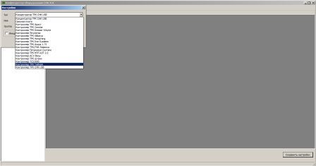
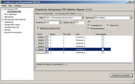
- Выберите COM-порт, к которому подключен преобразователь интерфейсов.
- Добавьте необходимое количество шлангов.
- При необходимости измените значение полей «Адрес» и «Пистолет».
- Для отпуска топлива на СУММУ установите галочку параметра «Заявка на целые литры».
- Нажмите кнопку «Сохранить».
Настройка в программе «Управление конфигурацией»:
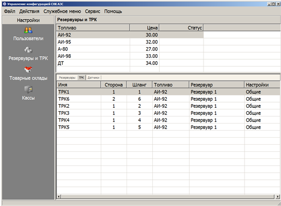
- Откройте приложение «Управление конфигурацией».
- Выберите вкладку «Резервуары и ТРК», экран ТРК.
- Создайте новую ТРК или отредактируйте существующую.
- Выберите канал контроллера.
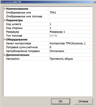
- При необходимости примените индивидуальные параметры.
Настройка ТРК Tokheim
Подготовка электроники ТРК
ТРК Tokheim имеет три типа запуска:
- Холодный пуск.
- Горячий пуск.
- Запуск для обслуживания.
Холодный пуск (COLD RESTART)
Для программирования всех параметров калькулятора ТРК требуется выполнить процедуру холодного пуска. Данный тип пуска может потребоваться при первом пуске ТРК, а также в случае появления сообщений об ошибках во время выполнения горячего пуска или запуска для обслуживания.
Внимание: Перед проведением процедуры COLD RESTART (Холодный пуск) необходимо отключить электропитание электроники ТРК. После выполнения процедуры холодного пуска потребуется полностью настроить конфигурацию ТРК.
Для выполнения сброса (обнуления) требуется:
1. Отключить электропитание электроники ТРК.
2. Проверить наличие интерфейсной платы WWC COMM TOKHEIM INTERFACE.
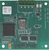
3. Снять джамперы W201 и W202, расположенные на центральной плате (Main Board v.4) электроники TOKHEIM.
4. Включить электропитание электроники ТРК.
ТРК перейдет в режим настроек и на дисплее отобразится мигающее сообщение «SEtUP PIncd». Для перехода к дальнейшим пунктам настройки потребуется ввод PIN-кода.
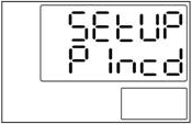
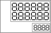
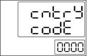
После ввода PIN-кода нажать клавишу «7». При вводе действительного PIN-кода ТРК выполнит процедуру самотестирования (мигающие 8-ки на дисплее) и перейдет к первому пункту меню настроек «cntrY code».
Вид дисплея при самотестировании:
Пункт меню cntrY code:
Программирование параметров работы ТРК TOKHEIM
Внимание: Для изменения параметров ТРК TOKHEIM необходима клавишная панель дистанционного управления (IRM) или внутренняя конфигурационная клавишная панель. Инфракрасный контроллер дистанционного управления является опцией.
В зависимости от версии ядра некоторые пункты меню могут отличаться от описанных далее.
Вид дистанционной клавишной панели (IRM):

Необходимо установить следующие параметры:
Код страны (обязательный параметр)
Необходимо установить параметр 0007, соответствующий «РОССИЯ». Для выбора параметра (кода) используется клавиша «9». Для возврата к значению «0000» необходимо нажать «0». Для подтверждения выбора и перехода к следующему меню нажать «7».
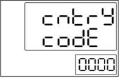
Если код страны не выбран, появится сообщение об ошибке.
Положение десятичной запятой Euro YES/NO
Необходимо установить значение «NO». Данный параметр определяет положение десятичной запятой, заданное по настройке (коду) для страны.

Для выбора параметра используется клавиша «9». Для подтверждения выбора и перехода к следующему меню нажать «7».
Положение десятичной запятой при отображении цены ScalE
Необходимое значение «0». В данном меню можно изменить положение десятичной запятой для цены за единицу.
Значение «Х» можно увеличить с помощью клавиши «9», пока не будет достигнуто нужное значение. Для подтверждения выбора и перехода к следующему меню нажать «7».
Единица измерения GALLON/LITER
Требуемое значение «no» для измерений в литрах. Это параметр задает единицы измерения продукта.
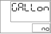
Для выбора параметра используется клавиша «9». Для подтверждения выбора и перехода к следующему меню нажать «7».
Код настройки diSP SEtUP (обязательный параметр)
Значение должно соответствовать гидравлической схеме.
Для выбора параметра используется клавиша «9». Для подтверждения выбора и перехода к следующему меню нажать «7».
Максимальное количество рукавов для сторон ТРК
Максимальное значение зависит от кода настройки, но не может быть больше 6.
Установить значение для правой стороны. Справа мигает значение «X». Значение «X» можно увеличить с помощью клавиши «9», пока не будет достигнуто нужное значение. Для переключения между сторонами нажать клавишу «8».
Установить значение для левой стороны. Слева мигает значение «X». Значение «X» можно увеличить с помощью клавиши «9», пока не будет достигнуто нужное значение. Для подтверждения выбора и перехода к следующему меню нажать клавишу «7».
Обнаружение утечки паров
После выполнения этого пункта меню необходимо установить перемычку W201 .
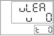
Это последний пункт начальных настроек.
Внимание: На этом этапе выполнения начальных настроек необходимо вставить перемычку W201 во избежание повторного холодного пуска.
При этом происходит автоматический перезапуск калькулятора. В память EEPROM будут записаны новые конфигурационные данные.
Если в процессе автоматического перезапуска будут обнаружены несоответствия оборудования и заданных параметров, появится сообщение об ошибке.
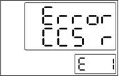
Сообщение содержит код возникшей ошибки. Пояснения кодов содержатся в документации производителя.
Сообщения об ошибках мигают в течение нескольких секунд, после чего электроника переходит к первому пункту меню начальных установок.
Настройка WWC T1
Все дальнейшие настройки производятся на уровне техника АЗС.
Для перехода в режим конфигурации (сервисный) необходимо нажать клавишу «ON» на конфигурационной клавишной панели. Колонка перейдет в режим конфигурирования. На дисплее ТРК будет отображено текущее состояние ТРК – «conF».
Вид дисплея при переходе в режим настроек:

Важно: При проведении операций программирования все пистолеты на обеих сторонах ТРК должны быть повешены.
Дальнейший порядок действий:
1. Нажать клавишу «5» для перехода в меню технических настроек ТРК. На дисплее колонки будет отображен мигающий пункт входа в техническое меню «tEcH».
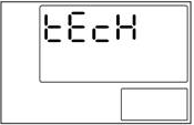
Вход в меню осуществляется по нажатию клавиши «7». Далее по запросу системы на ввод PIN-кода нужно еще раз нажать «7». На дисплее ТРК будет отображено сообщение с приглашением ввести четырехзначный PIN-код техника АЗС (мигает левый символ «-«).
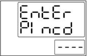
На этом этапе необходимо ввести PIN-код техника АЗС. При вводе недействительного PIN-кода на дисплее будет мигать сообщение «Error» в течение нескольких секунд, а затем калькулятор ТРК перейдет в предыдущее меню для ввода PIN-кода.
При вводе правильного PIN-кода ТРК перейдет к первому пункту меню технических настроек «diAG LoG» (журнал диагностики).
2. Переустановка термозащиты. Эта функция служит для управления термозащитой двигателя. Для перехода к соответствующему пункту меню используется клавиша «7» панели клавишного управления.
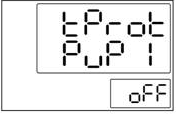
Если термозащита двигателя отключена, калькулятор не будет включать двигатель. Для выбора номера двигателя используется клавиша «8». Для переключения между «on» (Вкл) и «off» (Выкл) нажимать «9». Номер двигателя зависит от установок гидравлической системы ТРК. Для подтверждения выбора и перехода к следующему меню нажать «7».
Адрес узла (обязательный параметр)
Для программирования адреса правой стороны ТРК необходимо выбрать пункт меню «node Addr r», для левой – «node Addr L».
Адреса должны быть различными в пределах одного контроллера. Сначала задается адрес для правой стороны ТРК, а затем для левой.
Для увеличения значения используется клавиша «9». Для подтверждения выбора и перехода к следующему меню нажать «7».
Выход из режима обслуживания
Выйти из режима обслуживания можно на любом этапе программирования. Для выхода из режима необходимо нажимать клавишу «0».
Важно: Перед выходом из режима обслуживания необходимо, чтобы все пистолеты на обеих сторонах ТРК были повешены.
Для выхода из режима обслуживания нажать клавишу «OFF» дистанционной клавишной панели. Появится запрос о сохранении произведенных изменений в памяти ТРК:
При выходе из режима обслуживания и подтверждении запроса на сохранение параметров будет произведена проверка конфигурации (самотестирование).
В случае обнаружения критической ошибки в конфигурации на индикаторах ТРК появится сообщение «Error» и электроника перейдет к начальному меню настроек.
Источник
Tokheim
Tokheim («Токхайм») — торговая марка, которая имеет мировую известность, более чем вековую историю и принадлежит компании Tokheim Group. Под брендом Tokheim производятся топливораздаточные колонки (ТРК), а также технологические системы для обслуживания автозаправочных станций. Оборудование Токхейм работает в 120 странах мира на более чем 40 тысячах АЗС.
Tokheim — уникальность предлагаемых продуктов и синергетический эффект от их комплексного использования.
Сегодня головной офис производителя трк токхейм находится недалеко от Парижа. Но начиналась история бренда в США, когда в 1890 году купец из штата Айова Джон Токхайм изобрел и запатентовал первую систему перекачивания топлива. Этот прообраз современной топливораздаточной колонки стал настоящим прорывом в технологии быстрой и дозированной доставки потребителям различных видов топлива.

Сейчас под брендом Tokheim производятся одно- и двухпродуктовые ТРК, а также многофункциональные мультипродуктовые топливораздаточные комплексы для подачи бензина, дизельного топлива, метана и жидкого реагента AdBlue, очищающего выхлопные газы от дизельных двигателей.
На рынке представлены следующие серии оборудования Токхайм:
Потребители ТРК Токхайм отмечают целый ряд его преимуществ:
- идеальный баланс между ценой и качеством;
- выбор опций ТРК по желанию заказчика;
- возможность выбрать цвет колонки и нанести на нее логотип;
- устойчивая работа электроники;
- низкая восприимчивость к перепадам напряжения;
- антикоррозионная выносливость;
- наличие многоразовых фильтров, снижающих затраты на обслуживание ТРК;
- удобная система автоматического сматывания шлангов;
- безопасность.
Основная идея бренда Tokheim — комплексность обслуживания АЗС с достижением синергетического эффекта. Колонки Токхейм комплектуются платежными терминалами и мультимедийными системами для продвижения топливных продуктов. Владелец АЗС имеет возможность приобрести не просто оборудование, а готовый бизнес, в котором предусмотрены все технические и технологические решения – от строительства АЗС и их оснащения до рекламы продукции и постоянной технической поддержки станций.
Купить топливораздаточное оборудование Tokheim по цене завода-производителя можно в компании «Венго», оформив заявку и указав желаемую серию ТРК. Заявку можно оставить на сайте или позвонив по телефонам 8 800 222 44 52, +7 495 240 52 52.
Источник
-
Contents
-
Table of Contents
-
Bookmarks
Quick Links
WWC T1
Calculator
Set Up & Maintenance
Manual
Document Ref 905675-001
Rev — 2
01/2006
Related Manuals for Tokheim WWC T1
Summary of Contents for Tokheim WWC T1
-
Page 1
WWC T1 Calculator Set Up & Maintenance Manual Document Ref 905675-001 Rev — 2 01/2006… -
Page 2: Document Ref
Tokheim shall not be liable for damage to the product, nor for personal or third party injury, caused by incorrect use of the product or by attempts to maintain or to repair the product by parties other than those fully trained by Tokheim or by its accredited third party representatives.
-
Page 3
WWC T1 Set Up & Maintenance Manual Revision Record REVISION RECORD Date Revision Page Issue Reason 01/07/2004 Original Issue 19/01/2006 3 to 6 Main Contents revised 19/01/2006 2-16,2-17 Updated Functionalities 19/01/2006 2-21 to 2-23 New info added (Input Type, Master PIN Code, Gallon Type, Cent Overshoot Hide, 4 position product indicator, Heavy Lei);… -
Page 4
Revision Record WWC T1 Set Up & Maintenance Manual This page is intentionally blank Document Ref 905675-001 Rev 2… -
Page 5: Table Of Contents
WWC T1 Set Up & Maintenance Manual Contents CONTENTS INTRODUCTION ………………….1-2 How to Use this Manual ………………1-2 Product Scope ………………… 1-3 Authorised Technicians ………………1-3 Contact Information ……………….. 1-3 Health & Safety ………………..1-3 1.5.1 Safety Checklist ……………… 1-3 1.5.2…
-
Page 6
Contents WWC T1 Set Up & Maintenance Manual LPG SET UP / Timing with Deadmans Button only & Motor Off Delay ≠ ≠ ≠ ≠ ≠ 0 …. 3-7 3.3.3 3.3.4 Timing with Deadmans Button only & Motor Off Delay = 0 …. 3-7 SERVICE KEYPAD …………………. -
Page 7
WWC T1 Set Up & Maintenance Manual Contents MAINTENANCE MODE / 6.20 Node Address ………………..6-18 6.21 Test Delivery ………………… 6-19 6.22 Emergency Manual Pumping Device (EMPD) ……….6-21 6.23 Product Relation ………………..6-21 6.23.1 Product Name by Character Input ………… 6-22 6.23.2… -
Page 8
Contents WWC T1 Set Up & Maintenance Manual INSPECTION FUNCTIONS / 11.7 Release Management ………………11-4 11.8 Maximum Time for a Filling …………….11-4 11.9 Time Between Two Fillings …………….11-4 11.10 Maximum Time of No Flow …………….11-4 11.11 Maximum Time a Filling can be Suspended …………. 11-5 11.12 Timer for Display TImeout ……………. -
Page 9
WWC T1 Set Up & Maintenance Manual Introduction CONTENTS INTRODUCTION ………………….1-2 How to Use this Manual ………………1-2 Product Scope …………………. 1-3 Authorised Technicians ………………1-3 Contact Information ………………… 1-3 Health & Safety ………………..1-3 1.5.1 Safety Checklist ………………. 1-3 1.5.2… -
Page 10: Introduction
Section 2 — Product Information This section contains the system description and operating principles of the WWC T1 Calculator. It also describes the main components, their configurations and functions including the service keypads.
-
Page 11: Product Scope
WWC T1 Set Up & Maintenance Manual Introduction Product Scope This manual is designed to cover the Quantium T range of dispensers including LPG. As functionality is equivalent to the Coca 1.1 functionality, reference is frequently made to the existing Coca Manuals.
-
Page 12: Duties Of The Employees
Introduction WWC T1 Set Up & Maintenance Manual 1.5.2 DUTIES OF THE EMPLOYEES • To ensure optimal accident prevention in our company, in addition to general rules applying to worker’s protection, it is necessary to take into account all the national protection of workers legislation and to actively support all measures which enhance safety standards.
-
Page 13: Warning Signs
WWC T1 Set Up & Maintenance Manual Introduction At unattended service stations, every end-user should be able to read the User Instructions. They should be visible on a notice board or integrated into the DIT and should be sufficiently well lit so that they can be read at night.
-
Page 14: Personal Protective Equipment (Ppe)
Introduction WWC T1 Set Up & Maintenance Manual 1.5.5 PERSONAL PROTECTIVE EQUIPMENT (PPE) PROTECTIVE CLOTHING The following clothing should be worn at all times during installation and maintenance procedures:- • Protective helmet. • Protective shoes (conductive). • Protective gloves and/or protective hand cream.
-
Page 15: Nomenclature
WWC T1 Set Up & Maintenance Manual Introduction Nomenclature The various abbreviations used in thie manual are described as follows:- CoCa Today’s Common Calculator and base of the WWC CSD-F Common Sales Display — Ferranti CSD-L Common Sales Display — LCD…
-
Page 16
Introduction WWC T1 Set Up & Maintenance Manual This page is intentionally blank Page 1-8 Document Ref 905675-001 Rev 2… -
Page 17
WWC T1 Set Up & Maintenance Manual Product Information CONTENTS PRODUCT INFORMATION ………………2-2 System Description ………………..2-2 2.1.1 Operating Principles…………….2-2 Main Components of the WWC …………….2-2 2.2.1 External Power Supply ……………. 2-3 2.2.2 Mainboard ……………….. 2-3 2.2.3 I/O Board (version 3++) ………….. -
Page 18: Product Information
The WWC (World Wide Calculator) is a ‘measuring system’ built to conform to the international recommendations specified in the document OIML R117 Edition 1995. The WWC is also a peripheral within the different Tokheim filling station systems. As such, the WWC software and hardware can be configured without modifying the characteristics of the measuring system.
-
Page 19: External Power Supply
WWC T1 Set Up & Maintenance Manual Product Information ARCHITECTURAL OVERVIEW Valves, motors and sensors Displays CSD-L CSD-L CSD-F CSD-F Communication Mains Calculator Module Interfaces Battery I/O extensions Mainboard MB251 Nozzle Bus Dispenser light, Interface Electr totaliser Dipnet Low End Hydraulic…
-
Page 20: I/O Board (Version 3++)
Product Information WWC T1 Set Up & Maintenance Manual Since the release of Version 3 of the mainboard, the NBB board has been eliminated and the serial nozzle bus is directly controlled by the mainboard. Two optional modules can be directly connected to the mainboard (piggy-back):- •…
-
Page 21: Standard Dispensers With Up To Four Single Products
WWC T1 Set Up & Maintenance Manual Product Information 2.3.1 STANDARD DISPENSERS WITH UP TO FOUR SINGLE PRODUCTS Valves, motors and sensors Displays CSD-L CSD-L CSD-F CSD-F Communication Mains Calculator Module Interfaces Battery I/O extensions Mainboard MB251 Nozzle Bus Dispenser light,…
-
Page 22: Vapour Recovery Controller Board (Vrc)
Product Information WWC T1 Set Up & Maintenance Manual 2.3.3 VAPOUR RECOVERY CONTROLLER BOARD (VRC) The VRC is an independent module which communicates with the calculator module. After the VRC is initialised at each delivery start, it performs the open or closed loop vapour recovery process by controlling its own motors and valves.
-
Page 23: Functionalities Per Hose
WWC T1 Set Up & Maintenance Manual Product Information 2.5.1 FUNCTIONALITIES PER HOSE 40 (45) litres per minute — Petrol or Diesel Standard speed flow rate is achieved using one pump and one meter. 40 (45) litres per minute for two filling positions — Petrol or Diesel Standard speed flow rate is achieved using one pump and two meters.
-
Page 24
Product Information WWC T1 Set Up & Maintenance Manual The choice is made by push button selection with product indication. There are two principles:- • 2 grades in, 3 grades out, 2 hoses • 2 grades in, 3 grades out, 1 hose Refer to section 6.18 for programming information. -
Page 25
WWC T1 Set Up & Maintenance Manual Product Information If detected, the leak error is forwarded to the system and will immediately block the complete dispenser. The calculator keeps track of the leak status. Parameter: — hose expansion volume :… -
Page 26: Functionalities Per Side
Product Information WWC T1 Set Up & Maintenance Manual If the nozzle is replaced with volume = 0 before the time out expires, the leak sequence counter is neither incremented nor reset i.e. this will not increase the volume lost if it is a real leak.
-
Page 27
WWC T1 Set Up & Maintenance Manual Product Information Push Button Methods — Push buttons connected to the sensor bus or direct connections — Push buttons connected to the IEB Up to four buttons (three amount or volume and one reset button) are available and can be connected to the sensor bus, direct connections or via IEB at each filling position. -
Page 28
Product Information WWC T1 Set Up & Maintenance Manual Keypad Methods — Keypad connected to the IEB — Keypad connected to the OCB preset clear CREDIT preset amount preset CASH volume When Local Preset is connected using a keypad method, a 4×4 keypad is available at each filling position to allow the entry of a preset amount or preset volume. -
Page 29
WWC T1 Set Up & Maintenance Manual Product Information displays last delivery filling is cashed and the volume and amount display show “0” filling is cashed and all displays show “0” 3 to 9 reserved for future implementations Satellite Nozzle Control Menu A high speed diesel dispenser can have a satellite nozzle on each side. -
Page 30
Product Information WWC T1 Set Up & Maintenance Manual Parameters:- • function is disabled 0000 • max. time 0959 (= 9 minutes and 59 seconds) • default value 0100 (certain applications may overrule this) Time Between Two Fillings Menu (Inter delivery time out) This is the minimum time to elapse between two successive fillings. -
Page 31
WWC T1 Set Up & Maintenance Manual Product Information Note: The request to program EMT positions for left-hand dispensers (PMR297) means that the EMT connector must always be used for 4/5 products on the Optional Peripheral Board (OPB). OCB Functionality When an OCB board is connected, the following functions can be selected:- •… -
Page 32: Functionalities Per Dispenser
Product Information WWC T1 Set Up & Maintenance Manual — volume unit (number of cl/pulse) 1 to 10 (default = 1) — volume period (value * 0.25 ms) 5 to 40 (default = 5) — amount unit (number of units/pulse currency unit)
-
Page 33
WWC T1 Set Up & Maintenance Manual Product Information Kernel Hydr Additional No of Sided Flow Rates/Products Drawing No Version Setup No Description Products 130 l/min/SAT and 4×40 l/min 5 right 9235110584 (right); > 01.09 Asymmetric 4 left 4 x 40 l/min (left) -
Page 34
Product Information WWC T1 Set Up & Maintenance Manual Backlight for LCD The backlight is standard with LCD displays. Switch Dispenser Lighting If defined in the application, the switch for the dispenser or calculator lighting is via a command from the forecourt controller system. -
Page 35
WWC T1 Set Up & Maintenance Manual Product Information Node Address Menu This function is required for multi drop communication links (e.g. IFSF) to select the address of the calculator on the network. Refer to section 6.20 for programming information. -
Page 36
Product Information WWC T1 Set Up & Maintenance Manual Kernel version >= 02.xx Option Controller Board Hydraulic Controller Module CS1R CSD 1 Right CS2R CSD 2 Right CS1L CSD 1 Left CS2L CSD 2 Left Sound Option Module VRC Module… -
Page 37: Weights & Measures Related Functionality
WWC T1 Set Up & Maintenance Manual Product Information Nozzle Input Type This function allows the selection between two different types of nozzle input:- • Value “no” — normal nozzle switch position i.e. always OPEN in idle and CLOSED when nozzle lifted — for all dispensers except Q500T1.
-
Page 38
Product Information WWC T1 Set Up & Maintenance Manual Pulser Test Time Before starting a delivery, the pulser is tested during a specified ‘pulser test time’. During this test, the valves remain closed and the pulser is checked on consistent high/low values of both channels and there should be no pulses generated during this period. -
Page 39
WWC T1 Set Up & Maintenance Manual Product Information Note : For European Community countries, selection of the Euro is only possible up to kernel version 03.12. In later kernel versions, the Euro selection is fixed. Heavy Lei This function is designed to enable the conversion to Heavy Lei currency in Romania by simple (software) switch. -
Page 40
Product Information WWC T1 Set Up & Maintenance Manual Two EMT options are available for selection following a cold start:- • Value “d” = double-sided EMT (each nozzle of a product has an individual EMT total) • Value “s” = single-sided EMT (the left and right totals of the same product are… -
Page 41
WWC T1 Set Up & Maintenance Manual LPG Set Up CONTENTS LPG SET UP ……………………3-2 LPG Functionality ………………..3-2 3.1.1 LPG Pulse Menu …………….. 3-2 3.1.2 LPG Nozzle Flag Menu …………… 3-2 3.1.3 LPG Delay Timer Menu …………..3-3 3.1.4… -
Page 42: Lpg Set Up
LPG Set Up WWC T1 Set Up & Maintenance Manual LPG SET UP This section will cover the the hydraulic situation and the functional operation for LPG dispensers:- • LPG Functionality (refer to section 3.1) • LPG Hydraulic Functions (refer to section 3.2) •…
-
Page 43: Lpg Delay Timer Menu
WWC T1 Set Up & Maintenance Manual LPG Set Up • N = No nozzle switch present. The dispenser is activated by pressing the Deadmans Button. A delay timer is fitted (refer to section 3.1.3) to allow the customer to temporarily release the Deadmans Button without ending the delivery.
-
Page 44: Lpg Hydraulic Functions
LPG Set Up WWC T1 Set Up & Maintenance Manual LPG Hydraulic Functions In the LPG Hydraulic section, the basic flow is regulated by a valve in the liquid line, positioned before the break-away coupling and hose. For additional safety, the Hydraulic Chair option is available. The Chair hydraulic block may contain additional valves in the liquid line and vapour return line.
-
Page 45: Hydraulic Schematic
WWC T1 Set Up & Maintenance Manual LPG Set Up 3.2.2 HYDRAULIC SCHEMATIC RBU1 RNO1 RSV1 CHAIR RRV1 vapour liquid liquid WWC SET vapour LSV1 CHAIR LRV1 LNO1 LBU1 Note : The Hydraulic Chair block is an option. Where applicable, the additional valve in the vapour line (V…
-
Page 46: Functionality With Nozzle Switch
LPG Set Up WWC T1 Set Up & Maintenance Manual Functionality with Nozzle Switch TIMING WITH NOZZLE SWITCH & MOTOR OFF DELAY ≠ ≠ ≠ ≠ ≠ 0 3.3.1 nozzle button motor valve Start LPG Delay (Deadmans No action button)
-
Page 47: Functionality Without Nozzle Switch
WWC T1 Set Up & Maintenance Manual LPG Set Up Functionality without Nozzle Switch TIMING WITH DEADMANS BUTTON ONLY & MOTOR OFF DELAY ≠ ≠ ≠ ≠ ≠ 0 3.4.1 button motor valve Start LPG Delay (Deadmans button) Terminate Motor Off…
-
Page 48
LPG Set Up WWC T1 Set Up & Maintenance Manual This page is intentionally blank Page 3-8 Document Ref 905675-001 Rev 2… -
Page 49
WWC T1 Set Up & Maintenance Manual Set Up Modes CONTENTS SERVICE KEYPAD ………………… 4-2 User Access Keypad (UAK) …………….4-2 Infra Red (IR) Remote Control Keypad ………….. 4-4 Internal Configuration Keypad …………….4-4 Page 4-1 Document Ref 905675-001 Rev 2… -
Page 50: Service Keypad
Set Up Modes WWC T1 Set Up & Maintenance Manual SERVICE KEYPAD There are three types of keypads used in conjunction with the WWC:- • User Access Keypad (standard) — refer to section 4.1 • Inra-Red Remote Control (equal to CoCa) — refer to section 4.2 •…
-
Page 51
WWC T1 Set Up & Maintenance Manual Set Up Modes Symbol Calculator Function VRC Function Set unit price Start calibration Show totals Parameters keyboarding Application Set up Cancel current operation Set pincode Enter password Maintenance Functions Start maintenance Inspection Functions… -
Page 52: Infra Red (Ir) Remote Control Keypad
Set Up Modes WWC T1 Set Up & Maintenance Manual Infra Red (IR) Remote Control Keypad The IR Remote Control is available as an option for Station Managers to access the management functions of the calculator. Note: The IR option incurs an additional cost and is not suitable for VRC configuration or calibration.
-
Page 53
WWC T1 Set Up & Maintenance Manual Set Up Modes CONTENTS SET UP MODE ………………….5-2 General …………………… 5-2 Start Ups ………………….5-2 5.2.1 Cold Start ……………….. 5-2 5.2.2 Warm Start ………………5-3 5.2.3 Service Start ………………5-3 Initial Set Up Menu ………………… 5-3 5.3.1… -
Page 54: Set Up Mode
Set Up Modes WWC T1 Set Up & Maintenance Manual SET UP MODE General The set up of the calculator is a set of procedures which initialise the system according to the requirements of the dispenser itself and also individual customer requests. There are two main sequences to be followed:- •…
-
Page 55: Warm Start
WWC T1 Set Up & Maintenance Manual Set Up Modes After the 7 key is pressed, the initial setup will be mandatory (see section 5.3). Note : Remember to insert the jumper W201 after start up. 5.2.2 WARM START When jumper W201 is ON and W202 is OFF, the calculator performs a normal start up and all data from previous sessions is restored.
-
Page 56: Set Up Function Overview
5.3.1 SET UP FUNCTION OVERVIEW Function Kernel IFSF M3000 Dres K ER3 K S&B Country code Euro (always visible) > 01.12 Euro (European countries only) > 02.06 Scaling > 02.11 Gallon (always visible) > 01.12 Gallon (except country 001) > 02.06 Gallon type (if Gallon = yes only) >…
-
Page 57: Set Up Menu
WWC T1 Set Up & Maintenance Manual Set Up Modes 5.3.2 SET UP MENU The Set Up menu is executed when:- • A cold start is performed • Errors are detected with the set up during a warm start or a service start…
-
Page 58
Set Up Modes WWC T1 Set Up & Maintenance Manual Display Explanations/comments G A L L o n Gallon menu. Default no is flashing. Press 9 to toggle to yes to change the volume measurement to gallons. Press 7 to save and continue. -
Page 59
WWC T1 Set Up & Maintenance Manual Set Up Modes Display Explanations/comments Satellite/Slave Display menu. d I S P L The option for satellite/slave displays per dispenser side is defined within the set up code. Set satellite/slave display for the right side (side A):- The right 1 is flashing. -
Page 60
Set Up Modes WWC T1 Set Up & Maintenance Manual Display Explanations/comments EMT menu. e n n t Default d is flashing (double-sided). Press 9 to toggle to s for sigle-sided. Press 7 to save and continue. Combined Hose Product Preselection menu. -
Page 61
WWC T1 Set Up & Maintenance Manual Set Up Modes Display Explanations/comments Cent Overshoot Hide menu. n n A S Set the masking type:- t Y P E Use 9 to toggle between 1 (xxxx,x0 [default]) and 2 (xxxx,00) Note : France only (country code 33) Press 7 to save and continue. -
Page 62: Afm Set Up Menu
Set Up Modes WWC T1 Set Up & Maintenance Manual AFM Set Up Menu Display Explanations/comments AFM Set Up menu. Press 7 to skip AFM set up — this will disable any AFMs. S e t U P If AFM is not set, any attempt to start a delivery will generate error message 4 3 (pulser not connected).
-
Page 63
WWC T1 Set Up & Maintenance Manual Set Up Modes Y IS BLANK (INVALID OR MISSING AFM ADDRESS) Display Explanations/comments If the AFM address is invalid or not detected, y is blank. H o S E Check the following:- L E F t… -
Page 64
Set Up Modes WWC T1 Set Up & Maintenance Manual Y IS VALID ADDRESS Display Explanations/comments AFM Address menu. H o S E A valid address is displayed i.e. y is within the range 1 to 12. r I G H t Each AFM must be programmed according to the following procedures. -
Page 65
WWC T1 Set Up & Maintenance Manual Set Up Modes Display Explanations/comments Conversion: round 32768 K-factor Press 7 to save and continue. Close Seal menu. c L o S E Close the seal to save the new settings. S E A L Press 7 to save and continue. -
Page 66: Address Conflict
Set Up Modes WWC T1 Set Up & Maintenance Manual 5.4.2 ADDRESS CONFLICT Address Conflict If an address conflict is detected, the display will flash error in the volume line for approx. 3 seconds. e r r o r AFM Address menu.
-
Page 67
WWC T1 Set Up & Maintenance Manual Set Up Modes Address Conflict Change Address menu(only if seal is open). c H A n G E The address will correspond to the previously selected set up and A d d r number of hoses — refer to section 5.4.3. -
Page 68: Afm Addresses
Set Up Modes WWC T1 Set Up & Maintenance Manual 5.4.3 AFM ADDRESSES SINGLE METER/PRODUCT DEFINITIONS (SET UPS 50 AND 58) Product Hose number Comments number number address Right 1 Right 2 Right 3 Right 4 Reserved Reserved Reserved Reserved…
-
Page 69
WWC T1 Set Up & Maintenance Manual Maintenance Modes CONTENTS MAINTENANCE MODE ………………… 6-2 General …………………… 6-2 Maintenance Function Overview ……………. 6-2 Access the Maintenance Functions …………..6-4 Exit Maintenance Mode ………………6-5 Diagnostic Information (Error Log) …………..6-6 6.5.1 Kernel versions >… -
Page 70: Maintenance Mode
MAINTENANCE MODE General Within the initial set up mode, the parameters for several functions are given a default value. To prevent fraud, selected Weights & Measures related parameters defined during set up cannot be changed e.g. pulser hide, hose expansion, rounding type etc. — refer to Appendix B for further information.
-
Page 71
Issue B Function Kernel IFSF ZSR EPS Dun M3000 Tat Aut Dres K ER3 K S&B Tok Log EINF Combined Hose (set up = 90) > 03.07 EMT Mode > 03.09 > 03.24 Cent Overshoot Hide > 04.02 Q500T1 4 Position Product Indicator >… -
Page 72: Access The Maintenance Functions
Maintenance Modes WWC T1 Set Up & Maintenance Manual Access the Maintenance Functions Display Explanations/comments Press ON to enter Configuration. c o n F Press 5 to continue. Technicians menu. t E c H Tech is flashing. Press 7 to continue.
-
Page 73: Exit Maintenance Mode
WWC T1 Set Up & Maintenance Manual Maintenance Modes Exit Maintenance Mode If any Maintenance functions have been changed, the calculator automatically prompts for the storage of these modifications in Eeprom before exiting the Maintenance Functions menu. Display Explanations/comments Press 0 to return to Diagnostic Log (first menu).
-
Page 74: Diagnostic Information (Error Log)
Maintenance Modes WWC T1 Set Up & Maintenance Manual Diagnostic Information (Error Log) This menu provides access to the calculator’s error log where the error codes for each error database can be viewed. The database stores the last 100 errors/events since the last reset of the error log.
-
Page 75: Kernel Versions <= 01.07
WWC T1 Set Up & Maintenance Manual Maintenance Modes With kernel versions equal or less than 01.07 the diagnostic information is displayed in a different layout. For a detailed description, refer to Appendix C. 6.5.2 KERNEL VERSIONS <= 01.07 Display…
-
Page 76: Leak Tests
Maintenance Modes WWC T1 Set Up & Maintenance Manual Leak Tests Display Explanations/comments L E A French Leak Test menu (only if French Leak Test is activated). A c t v t E Press 7 to save and continue. L E A Esso Leak Test menu (only if the Esso Leak Test is activated).
-
Page 77
WWC T1 Set Up & Maintenance Manual Maintenance Modes Display Explanations/comments c n t r Y Country Code (as defined in initial Set Up). c o d E Note : This value is read-only and cannot be changed in this menu. -
Page 78: Lpg Functionality
Maintenance Modes WWC T1 Set Up & Maintenance Manual LPG Functionality This function enables the selection of a nozzle switch or Deadmans button and the ability to set a delay timer for stopping the motor after the LPG button is released accidentally.
-
Page 79: Thermal Protection Reset
WWC T1 Set Up & Maintenance Manual Maintenance Modes Thermal Protection Reset When the thermal protection of a motor is tripped, the calculator will not allow the motor to re-start without user intervention either via this menu or via an optional button.
-
Page 80: Leak Detection Functionality
Maintenance Modes WWC T1 Set Up & Maintenance Manual 6.10 Leak Detection Functionality This menu is displayed when the hose is activated and ready for use. Display Explanations/comments L E A Fuel Leak menu. The first product is displayed. Press 8 to increase the product number (right then left).
-
Page 81: Fraud Detection Functionality
WWC T1 Set Up & Maintenance Manual Maintenance Modes 6.10.3 ESSO LEAK DETECTION When Esso Leak Detection is activated and a leak is detected, the calculator will disable the associated dispenser which must be reset by user intervention via this menu. The Flow Leak menu changes into:-…
-
Page 82: Combined Hose Pre-Selection And Display Timeout
Maintenance Modes WWC T1 Set Up & Maintenance Manual 6.12 Combined Hose Pre-selection and Display Timeout The Combined Hose Pre-selection Menu is read-only and cannot be changed in this menu (set up 90 and Tatsuno application only). Display Explanations/comments P r o…
-
Page 83: Cent Overshoot Hide Functionality
WWC T1 Set Up & Maintenance Manual Maintenance Modes 6.14 Cent Overshoot Hide Functionality The Cent Overshoot Hide function is read-only and can only be changed in Set Up Mode. Note : This menu is only available with country code 33 (France).
-
Page 84: Stop/Off Switch
Maintenance Modes WWC T1 Set Up & Maintenance Manual 6.16 Stop/Off Switch This function allows the back-up battery to be switched off to enable Maintenance to be carried out in the event of a power failure. It is only available with kernel versions <=01.08.
-
Page 85: Blend Ratio
WWC T1 Set Up & Maintenance Manual Maintenance Modes 6.17.1 SET UP PIN CODE (FUEL LEAK DETECTION ONLY) A special Personal Identification Number (PIN) code is required to store any changes to the Fuel Leak Detection settings. Display Explanations/comments Set Up PIN Code menu.
-
Page 86: Local Preset Values
Maintenance Modes WWC T1 Set Up & Maintenance Manual 6.19 Local Preset Values Preset values are predefined (selected from a pick list) and are dependent upon the comma position as defined in Appendix A. For more information, refer to section 2.5.2.
-
Page 87: Test Delivery
WWC T1 Set Up & Maintenance Manual Maintenance Modes 6.21 Test Delivery During a test delivery, certain calculator functions can be tested and/or calibrated. If enabled, a test delivery message will appear on the unit price display. The exact message will depend on which test is enabled.
-
Page 88
Maintenance Modes WWC T1 Set Up & Maintenance Manual Display Explanations/comments The unit price display will alternate between Test and 0. The display reading setting allows meter information to be displayed on the volume/amount display. Depending on the test type, the following information will be displayed during a delivery:- 0 = normal readings i.e. -
Page 89: Emergency Manual Pumping Device (Empd)
WWC T1 Set Up & Maintenance Manual Maintenance Modes 6.22 Emergency Manual Pumping Device (EMPD) This special function of the WWC enables fuel to be dispensed manually (using handle on the pump) in the event of a power failure (using a back-up battery) by bypassing the motor/valves and recording the delivery on the pulser.
-
Page 90: Product Name By Character Input
Maintenance Modes WWC T1 Set Up & Maintenance Manual 6.23.1 PRODUCT NAME BY CHARACTER INPUT Display Explanations/comments o U t Product Name selection character by character. The first — is flashing. r I n 1 Press 9 to scroll through the character list to select the first character of the product name.
-
Page 91: Product Name From Pick List
WWC T1 Set Up & Maintenance Manual Maintenance Modes 6.23.2 PRODUCT NAME FROM PICK LIST Display Explanations/comments o U t Product Name from a Pick List. The first — is flashing. Press 3 to scroll through the pick list. r I n 1 Press 3 to select from a pick list.
-
Page 92: Vapour Recovery
Maintenance Modes WWC T1 Set Up & Maintenance Manual 6.24 Vapour Recovery The Vapour Recovery function is controlled via a separate Vapour Recovery Controller (VRC) or third party controlling module i.e. Fafnir, GRVP etc. This menu will indicate whether vapour recovery is applicable for a selected product. This menu is only visible if the system detects a VRC board.
-
Page 93: Vapour Delay
WWC T1 Set Up & Maintenance Manual Maintenance Modes 6.25 Vapour Delay This function (implemented since kernel version 3.03) enables extended vapour recovery error checking and reporting if the parameter >0. If the VRC system is running in SCG (self calibrating gas) mode and detects a problem in a hose then the error will be reported to the kiosk.
-
Page 94: Optional Preset Valve
Maintenance Modes WWC T1 Set Up & Maintenance Manual 6.27 Optional Preset Valve This function allows the use of a low flow valve (reduction valve) in parallel with the normal flow valve (stop valve) so that during a delivery, both valves are opened. It is designed to support the use of different preset valve mechanisms.
-
Page 95: Afm Menu
WWC T1 Set Up & Maintenance Manual Maintenance Modes 6.29 AFM Menu This menu will allow the configuration of Axial Flow volume meters. Display Explanations/comments At the Maintenance menu, press 7 to scroll through the options c o n F until the AFM Configuration menu is displayed.
-
Page 96
Maintenance Modes WWC T1 Set Up & Maintenance Manual Display Explanations/comments y y y y w w Serial Number menu (only if AFM is connected and initialised). n n n n n n information displayed:- yyyy = year ww = week nnnnnn = serial number Press 7 to continue. -
Page 97: Product Position
WWC T1 Set Up & Maintenance Manual Maintenance Modes 6.30 Product Position This function assigns the position of Product Indicators, Electro-mechanical Totalisers (EMT) and Unit Price Displays (UPD) to calculator internal product codes. For more information, refer to section 2.5.2. Also refer to kernel versions according to section 6.2 Maintenance Function Overview.
-
Page 98: Option Selection
Maintenance Modes WWC T1 Set Up & Maintenance Manual 6.31 Option Selection Option selection is by means of one of the following ways:- • I/O Extention Board (IEB ) — refer to section 6.29.1 • Option Controller Board (OCB) — refer to section 6.29.2 6.31.1…
-
Page 99: Ocb (Option Controller Board) Options
WWC T1 Set Up & Maintenance Manual Maintenance Modes 6.31.2 OCB (OPTION CONTROLLER BOARD) OPTIONS The parameter values are 0 to 9 for all options:- option disabled (default) controlled by application (selected applications can overrule the kernel functionality). Note : few applications use different functionality than the standard functionality.
-
Page 100
Maintenance Modes WWC T1 Set Up & Maintenance Manual For all other applications, the menu appears as follows:- Display Explanations/comments o c b OCB menu. Press 8 to enter OCB menu. Traffic Lights menu. L I G H t S Default off is flashing. -
Page 101
WWC T1 Set Up & Maintenance Manual Maintenance Modes Display Explanations/comments Volume/Amount Pulse menu. v o L A U Press 8 to enter submenu. Press 0 to exit OCB menu. v o L U Volume Pulse submenu (number of pulses per cl). -
Page 102
Maintenance Modes WWC T1 Set Up & Maintenance Manual Kernel versions 01.12 – 01.16 Display Explanations/comments o c b OCB menu. Press 8 to enter OCB menu. Traffic Lights menu. L I G H t S Default 0 is flashing. Press 9 to change value to:-… -
Page 103
WWC T1 Set Up & Maintenance Manual Maintenance Modes Kernel versions 01.08 – 01.11 Display Explanations/comments o c b OCB menu. Press 8 to enter OCB menu. Traffic Lights menu. L I G H t S Default 0 is flashing. Press 9 to change value to:-… -
Page 104
Maintenance Modes WWC T1 Set Up & Maintenance Manual Kernel versions <= 01.07 Display Explanations/comments o c b OCB menu. Press 8 to enter OCB menu. t r A F F Traffic Lights menu (dispenser status — green = on) L I G H t Default 0 is flashing. -
Page 105: Nozzle Sensor Definition
WWC T1 Set Up & Maintenance Manual Maintenance Modes 6.32 Nozzle Sensor Definition This menu allows sensor numbers to be changed in order to match the pre-installed sensors with the correct functions. e.g. For replacing of a faulty sensor with a new one with a different address.
-
Page 106
Maintenance Modes WWC T1 Set Up & Maintenance Manual Display Explanations/comments S E n S o r Sensor Activate submenu. t E S t The current activated sensor will be displayed with its function as described above. Press 7 to go to next submenu (Change Sensor). -
Page 107
WWC T1 Set Up & Maintenance Manual Maintenance Modes Display Explanations/comments Press 8 to enter this submenu. Press 0 to return to nbus menu. Press 7 to skip and go to next menu (Program Sensor). E r A S E All connected sensors are erased. -
Page 108: Kernel Version >= 02.12
Maintenance Modes WWC T1 Set Up & Maintenance Manual 6.32.3 KERNEL VERSION >= 02.12 Display Explanations/comments n b b Nozzle Sensor Definition menu. Press 8 to enter this menu. d I S P L Display Sensor submenu. S E n S o r All installed sensors are displayed with their specific functions.
-
Page 109
WWC T1 Set Up & Maintenance Manual Maintenance Modes Display Explanations/comments S E n Store changes setting. Press 9 to toggle between yes (store changes) and no (exit without storing changes). Y E S Press 0 to save and continue. -
Page 110: Kernel Version < 02.12
Maintenance Modes WWC T1 Set Up & Maintenance Manual 6.32.4 KERNEL VERSION < 02.12 Display Explanations/comments n b b Nozzle Sensor Definition menu. Press 8 to enter this menu. o L d Replace old sensor number with new sensor number.
-
Page 111
WWC T1 Set Up & Maintenance Manual Application Mode CONTENTS APPLICATION MODE ………………..7-2 All Applications ………………..7-2 EPS ……………………7-3 IFSF ……………………7-4 ZSR ……………………7-5 Dunclare ………………….7-6 Tokheim ………………….7-7 Page 7-1 Document Ref 905675-001 Rev 2… -
Page 112: Application Mode
Application Mode WWC T1 Set Up & Maintenance Manual APPLICATION MODE All Applications Display Explanations/comments Press ON to enter Configuration. c o n F Press 3 to enter Application Mode. APPLIc is flashing. A P P L I c Press 7 to continue.
-
Page 113: Eps
WWC T1 Set Up & Maintenance Manual Application Mode Display Explanations/comments EPS 3 is flashing. E P S Press 9 to toggle between 3 and 5. Note : EPS 5 functionality will enable sending of EPS/5 messages to the k iosk ; send totals when connected to k iosk ;…
-
Page 114: Ifsf
Application Mode WWC T1 Set Up & Maintenance Manual IFSF Display Explanations/comments v o L L I Volume Limit menu (UK only). Press 9 to set the volume limit. Press 7 to save and continue. 8 8 8 8 8 8 Display Test menu (UK only).
-
Page 115: Zsr
WWC T1 Set Up & Maintenance Manual Application Mode Display Explanations/comments d o S DOS Task Interface Timing menu. t I m Note : SC30 specific timing delays are excluded and the release process made quick er. Default no is flashing. Press 9 to to ggle to yes (select DOS/ Schenk interface).
-
Page 116: Dunclare
Application Mode WWC T1 Set Up & Maintenance Manual Dunclare Display Explanations/comments v o L L I Volume Limit menu. 0 1 0 0 0 0 Default 1000 is flashing. Press 9 to change the value. Press 8 to change another digit.
-
Page 117: Tokheim
WWC T1 Set Up & Maintenance Manual Application Mode Tokheim Display Explanations/comments Delivery Volume x10 menu. v o L — 1 0 For use with old MEMs systems in order to shift the incoming and outgoing delivery volumes. Press 9 to toggle between yes (enable) and no (disable).
-
Page 118
Application Mode WWC T1 Set Up & Maintenance Manual This page is intentionally blank Page 7-8 Document Ref 905675-001 Rev 2… -
Page 119
WWC T1 Set Up & Maintenance Manual PIN Codes CONTENTS PIN CODES ……………………8-2 First PIN code ………………….8-2 Change PIN code ………………..8-3 Page 8-1 Document Ref 905675-001 Rev 2… -
Page 120: Pin Codes
PIN Codes WWC T1 Set Up & Maintenance Manual PIN CODES The PIN Code functionality is equal to Coca 1.1 with the following exceptions:- • The Station Manager PIN code is replaced by a keylock (local regulation). • With the Calculator Housing CLOSED, the Station Manager PIN code allows read-only access.
-
Page 121: Change Pin Code
WWC T1 Set Up & Maintenance Manual PIN Codes Change PIN code Display Explanations/comments X X X X X X All displays show X . X X X X X X X X X X Select ON c o n F Configure PIN code menu.
-
Page 122
PIN Codes WWC T1 Set Up & Maintenance Manual Display Explanations/comments E E P r o Memory Store menu. S t o r E Press 9 to toggle yes (save) and no (exit without save). Y E S Press 7 to continue. -
Page 123
WWC T1 Set Up & Maintenance Manual Totals CONTENTS TOTALS ……………………. 9-2 Reading the Totals (Amount, Volume & Number of Deliveries) ……. 9-2 Page 9-1 Document Ref 905675-001 Rev 2… -
Page 124: Totals
Totals WWC T1 Set Up & Maintenance Manual TOTALS Reading the Totals (Amount, Volume & Number of Deliveries) In the Read Totals menu, the total amount, total volume and total number of deliveries per product are displayed by lifting the relevant nozzle. It is also possible to see the total volume per volume meter and the total volume per nozzle.
-
Page 125
WWC T1 Set Up & Maintenance Manual Totals Display Explanations/comments At the Unit Price line, the t nr (total number of deliveries) and p 1 (product 1) are flashing. Replace the nozzle to continue reading the totals. Press 0 to return to Totals menu. -
Page 126
Totals WWC T1 Set Up & Maintenance Manual Display Explanations/comments — — — — — — The display will return to dashes. — — — — — — Lift a nozzle to read the sub-totals for that product. — — — — Press 0 to return to Sub-Totals menu. -
Page 127
WWC T1 Set Up & Maintenance Manual Totals Display Explanations/comments d I S P Dispenser Totals menu. t o t A L Press 7 to select another type of total. Press 0 to return to CONF menu. Press 8 to enter this menu. -
Page 128
Totals WWC T1 Set Up & Maintenance Manual Display Explanations/comments Total amount of false flow for prod 2 on right side (side A) is 1 2 3 4 displayed. r 2 A u Press 7 for the next hose. Press 8 to go to total volume for this hose. -
Page 129
WWC T1 Set Up & Maintenance Manual Unit Prices CONTENTS UNIT PRICES ………………….10-2 10.1 Set/Change Unit Prices ………………10-2 Page 10-1 Document Ref 905675-001 Rev 2… -
Page 130: Unit Prices
Unit Prices WWC T1 Set Up & Maintenance Manual UNIT PRICES Functionality equal to Coca 1.1. 10.1 Set/Change Unit Prices Display Explanations/comments X X X X X X All displays show X . X X X X X X X X X X Select ON .
-
Page 131
WWC T1 Set Up & Maintenance Manual Unit Prices Display Explanations/comments P r o d Enter Unit Price for Product 1 on the left side (side B):- L E F t Repeat for each product on the left side (side B) up to max of X X X X 6 fuel grades. -
Page 132
Unit Prices WWC T1 Set Up & Maintenance Manual This page is intentionally blank Page 10-4 Document Ref 905675-001 Rev 2… -
Page 133: Inspection Functions
WWC T1 Set Up & Maintenance Manual Inspection Functions CONTENTS INSPECTION FUNCTIONS ………………11-2 11.1 Inspection Function Overview …………….11-2 11.2 General ………………….. 11-3 11.3 Delivery Mode ………………..11-3 11.4 Traffic Lights ………………… 11-3 11.5 Idle Display Control ………………. 11-3 11.6…
-
Page 134: Inspection Function Overview
INSPECTION FUNCTIONS Functionality equal to Coca 1.1 with the exception of the version numbers menu. 11.1 Inspection Function Overview K ER3 — Kienzle ER3, K S&B — Kienzle S&B Function IFSF M3000 Dres K ER3 K S&B Kernel Delivery Mode Traffic Light <…
-
Page 135: General
WWC T1 Set Up & Maintenance Manual Inspection Functions 11.2 General In the Inspection Functions menu, the parameters for certain functions have default values or are disabled. Applications can overrule the default settings — refer to the appropriate Release Notes for further information.
-
Page 136: Release Management
Inspection Functions WWC T1 Set Up & Maintenance Manual 11.7 Release Management Release a dispenser for the next filling:- r E L E A r E L E A S E L c t S E L c t 0 = Release via system only — no manual release possible…
-
Page 137: 11.11 Maximum Time A Filling Can Be Suspended
WWC T1 Set Up & Maintenance Manual Inspection Functions 11.11 Maximum Time a Filling can be Suspended Within this set time, a filling must be started (released via Payment Terminal) or continued at a slave/satellite dispenser. If this time is exceeded, the filling is ended and the dispenser must be released before it can be used again.
-
Page 138
Inspection Functions WWC T1 Set Up & Maintenance Manual Display Explanations/comments 8 8 8 8 8 8 All displays show 8 . 8 8 8 8 8 8 The calculator is checking for connected peripherals. 8 8 8 8 Press 7 to go to next peripheral. -
Page 139
WWC T1 Set Up & Maintenance Manual Inspection Functions Display Explanations/comments The UAM software version is displayed. Press 0 to return to Software Version menu. 0 1 0 2 Press 7 to go to next peripheral. The HOM X software version is displayed (X = 1,2,3,4). -
Page 140: 11.15 Pulser Hide
Inspection Functions WWC T1 Set Up & Maintenance Manual 11.15 Pulser Hide If the Pulser Hide function is activated, the first X pulses dispensed do not appear on the display i.e. the display remains 0. When next pulse (X+1) is received, the display will show the total (X+1).
-
Page 141: Appendix
WWC T1 Set Up & Maintenance Manual Appendix CONTENTS APPENDIX ……………………12-2 12.1 Appendix A — Product Option Matrix …………… 12-2 12.2 Appendix B — Country Codes …………….12-4 12.3 Appendix C — Error Codes …………….12-6 12.3.1 Startup Error Situations …………..12-6 12.3.2…
-
Page 142: Appendix A — Product Option Matrix
APPENDIX 12.1 Appendix A — Product Option Matrix K ER3 — Kienzle ER3, K S&B — Kienzle S&B Option description IFSF M3000 Dres K ER3 K S&B Application dependent Blender Combined Hose Manual release Car Detection X (CH) Voice synthesizer (SOM) Programming Switch (writing data with remote if head open) Indication light (red or white)
-
Page 143
Issue B Option description IFSF M3000 Dres K ER3 K S&B MPD with sat hose (80 or 130) on 1 side Satellite connection 80 l/min Satellite connection 130 l/min Continuous filling button for satellite 130 l/min as single product on 1 side (MPD) Oil mixer Unit price display… -
Page 144: Appendix B — Country Codes
Appendix WWC T1 Set Up & Maintenance Manual 12.2 Appendix B — Country Codes Key:- In USA the pulser resolution is 0,0005 Gallons. Therefore these values are expressed in this unit. Comma Position , The position of the comma on the displays for amount/volume/unit price is counted from the RIGHT side.
-
Page 145
WWC T1 Set Up & Maintenance Manual Appendix Hose Expansion Position in Rounding Pulse Hide Code Country Euro Software time/value Type One Meter Two Meters 0001 2/3/3 Fixed: 30/21(*) 5(*) 5(*) 0007 Russia 2/2/2 Fixed: 30/8 0020 Egypt 2/2/2 Fixed: 30/8… -
Page 146: Appendix C — Error Codes
Appendix WWC T1 Set Up & Maintenance Manual 12.3 Appendix C — Error Codes 12.3.1 STARTUP ERROR SITUATIONS “LRC ERROR” flashing on display The system will not start. EPROM has been patched or is invalid and must be replaced. Calculator does not start and “CAM251_RUN_LED” is flashing on display RAM error — exchange the Mainboard.
-
Page 147: Diagnostic Database
WWC T1 Set Up & Maintenance Manual Appendix LIST OF PERIPHERAL TYPES Component indication Application Kernel Customer Sales display Sound Option Module User Access Module Option Controller Board Subcategory of peripheral HCM 0 General HCM error e.g. totaliser, dispenser light, high speed valve…
-
Page 148
Appendix WWC T1 Set Up & Maintenance Manual HCM/HOM ERRORS Main event code Sub event code 1 DIPNET DRIVER ERROR 1 MAX NR OF REQUESTS (HM DRIVER MAIN) 2 DIPNET TIMEOUT 3 DIPNET ERROR 4 STATE TRANSITION ERROR 2 GENERAL HCM/HOM ERROR… -
Page 149
WWC T1 Set Up & Maintenance Manual Appendix CUSTOMER SALES DISPLAY ERRORS Main event code Sub event code 1 COMMUNICATION LOST SOUND OPTION MODULE ERRORS Main event code Sub event code 1 GENERAL ERROR USER ACCESS MODULE ERRORS Main event code… -
Page 150: Appendix D — Jumper Positions
Appendix WWC T1 Set Up & Maintenance Manual 12.4 Appendix D — Jumper Positions 12.4.1 MAINBOARD For the latest board revisions, please refer to the appropriate Product Specification Sheet. Bus to/from I/O Nozzles & Buttons from Nozzles & Pulsers Board X117…
-
Page 151: Vrc Board
WWC T1 Set Up & Maintenance Manual Appendix 12.4.2 VRC BOARD Valve Left DIPNET Valve Right EPM7064 28F010 OL / CL 80C251 CL type Motor Left Motor Right ERROR LED’s ERZ barrier Right-product 3 Left-product 1 Left-product 2 Right-product 2…
-
Page 152: User Access Module
Appendix WWC T1 Set Up & Maintenance Manual 12.4.3 USER ACCESS MODULE ECVR METER 87C52 DIPNET sensor keyboard 87C52 DIPNET sensor LED’s: • LED_1 (H4 = RED) Normal operation • LED_2 (H5 = GREEN) Key activated Jumpers: • IR remote sensor for IR remote control •…
-
Page 153: Ocb Board
WWC T1 Set Up & Maintenance Manual Appendix 12.4.4 OCB BOARD UPD_L UPD_R DIPNET KEY_L W202 KEY_R W201 OUT_SPARE OUT_YELLOW OUT_RED OUT_GREEN 87C52 POWER LCD_L W501 OPTO_INPUT H201 GROUND AMOUNT_2 H202 AMOUNT_1 LCD_R VOLUME_2 VOLUME_1 W502 POWER LED’s: •LED_1 (H201 = YELLOW) Normal operation •…
-
Page 154: I/O Extension Board (Ieb)
Appendix WWC T1 Set Up & Maintenance Manual 12.4.5 I/O EXTENSION BOARD (IEB) • W300 OFF Preset Keypad • W300 ON Preset Buttons • W301 Not used • W302 Not used 12.4.6 HYDRAULIC OPTION MODULE (HOM) W201 Not used W202…
-
Page 155: Appendix E — General Purpose Inputs
WWC T1 Set Up & Maintenance Manual Appendix 12.5 Appendix E — General Purpose Inputs Application GPI 1 GPI 2 GPI 3 GPI 4 IFSF enable standalone switch configuration read only tank level input left tank level input right configuration read only…
-
Page 156: Appendix F- Ieb General Purpose Outputs
Appendix WWC T1 Set Up & Maintenance Manual 12.6 Appendix F- IEB General Purpose Outputs The functions in the table below are the application controlled functions. GPO menu parameter = 1 (refer to section 6.29.1) Application GPO 1 GPO 2…
-
Page 157
WWC T1 Set Up & Maintenance Manual This page is intentionally blank Document Ref 905675-001 Rev 2… -
Page 158
1762 Givisiez +49 (0) 89 189 533 99 +41 (0)26 460 51 11 service@muenchen.tokheim.com +41 (0)26 460 51 12 As Tokheim regularly improves its prod- user@givisiez.tokheim.com ucts to ever better respond to evolving market and regulatory requirements, it Italy United Kingdom reserves the right to change any of the Tokheim Sofitam Italia S.r.l.
-
Contents
-
Table of Contents
-
Bookmarks
Quick Links
WWC T1
Calculator
Set Up & Maintenance
Manual
Document Ref 905675-001
Rev — 2
01/2006
Related Manuals for Tokheim WWC T1
Summary of Contents for Tokheim WWC T1
-
Page 1
WWC T1 Calculator Set Up & Maintenance Manual Document Ref 905675-001 Rev — 2 01/2006… -
Page 2: Document Ref
Tokheim shall not be liable for damage to the product, nor for personal or third party injury, caused by incorrect use of the product or by attempts to maintain or to repair the product by parties other than those fully trained by Tokheim or by its accredited third party representatives.
-
Page 3
WWC T1 Set Up & Maintenance Manual Revision Record REVISION RECORD Date Revision Page Issue Reason 01/07/2004 Original Issue 19/01/2006 3 to 6 Main Contents revised 19/01/2006 2-16,2-17 Updated Functionalities 19/01/2006 2-21 to 2-23 New info added (Input Type, Master PIN Code, Gallon Type, Cent Overshoot Hide, 4 position product indicator, Heavy Lei);… -
Page 4
Revision Record WWC T1 Set Up & Maintenance Manual This page is intentionally blank Document Ref 905675-001 Rev 2… -
Page 5: Table Of Contents
WWC T1 Set Up & Maintenance Manual Contents CONTENTS INTRODUCTION ………………….1-2 How to Use this Manual ………………1-2 Product Scope ………………… 1-3 Authorised Technicians ………………1-3 Contact Information ……………….. 1-3 Health & Safety ………………..1-3 1.5.1 Safety Checklist ……………… 1-3 1.5.2…
-
Page 6
Contents WWC T1 Set Up & Maintenance Manual LPG SET UP / Timing with Deadmans Button only & Motor Off Delay ≠ ≠ ≠ ≠ ≠ 0 …. 3-7 3.3.3 3.3.4 Timing with Deadmans Button only & Motor Off Delay = 0 …. 3-7 SERVICE KEYPAD …………………. -
Page 7
WWC T1 Set Up & Maintenance Manual Contents MAINTENANCE MODE / 6.20 Node Address ………………..6-18 6.21 Test Delivery ………………… 6-19 6.22 Emergency Manual Pumping Device (EMPD) ……….6-21 6.23 Product Relation ………………..6-21 6.23.1 Product Name by Character Input ………… 6-22 6.23.2… -
Page 8
Contents WWC T1 Set Up & Maintenance Manual INSPECTION FUNCTIONS / 11.7 Release Management ………………11-4 11.8 Maximum Time for a Filling …………….11-4 11.9 Time Between Two Fillings …………….11-4 11.10 Maximum Time of No Flow …………….11-4 11.11 Maximum Time a Filling can be Suspended …………. 11-5 11.12 Timer for Display TImeout ……………. -
Page 9
WWC T1 Set Up & Maintenance Manual Introduction CONTENTS INTRODUCTION ………………….1-2 How to Use this Manual ………………1-2 Product Scope …………………. 1-3 Authorised Technicians ………………1-3 Contact Information ………………… 1-3 Health & Safety ………………..1-3 1.5.1 Safety Checklist ………………. 1-3 1.5.2… -
Page 10: Introduction
Section 2 — Product Information This section contains the system description and operating principles of the WWC T1 Calculator. It also describes the main components, their configurations and functions including the service keypads.
-
Page 11: Product Scope
WWC T1 Set Up & Maintenance Manual Introduction Product Scope This manual is designed to cover the Quantium T range of dispensers including LPG. As functionality is equivalent to the Coca 1.1 functionality, reference is frequently made to the existing Coca Manuals.
-
Page 12: Duties Of The Employees
Introduction WWC T1 Set Up & Maintenance Manual 1.5.2 DUTIES OF THE EMPLOYEES • To ensure optimal accident prevention in our company, in addition to general rules applying to worker’s protection, it is necessary to take into account all the national protection of workers legislation and to actively support all measures which enhance safety standards.
-
Page 13: Warning Signs
WWC T1 Set Up & Maintenance Manual Introduction At unattended service stations, every end-user should be able to read the User Instructions. They should be visible on a notice board or integrated into the DIT and should be sufficiently well lit so that they can be read at night.
-
Page 14: Personal Protective Equipment (Ppe)
Introduction WWC T1 Set Up & Maintenance Manual 1.5.5 PERSONAL PROTECTIVE EQUIPMENT (PPE) PROTECTIVE CLOTHING The following clothing should be worn at all times during installation and maintenance procedures:- • Protective helmet. • Protective shoes (conductive). • Protective gloves and/or protective hand cream.
-
Page 15: Nomenclature
WWC T1 Set Up & Maintenance Manual Introduction Nomenclature The various abbreviations used in thie manual are described as follows:- CoCa Today’s Common Calculator and base of the WWC CSD-F Common Sales Display — Ferranti CSD-L Common Sales Display — LCD…
-
Page 16
Introduction WWC T1 Set Up & Maintenance Manual This page is intentionally blank Page 1-8 Document Ref 905675-001 Rev 2… -
Page 17
WWC T1 Set Up & Maintenance Manual Product Information CONTENTS PRODUCT INFORMATION ………………2-2 System Description ………………..2-2 2.1.1 Operating Principles…………….2-2 Main Components of the WWC …………….2-2 2.2.1 External Power Supply ……………. 2-3 2.2.2 Mainboard ……………….. 2-3 2.2.3 I/O Board (version 3++) ………….. -
Page 18: Product Information
The WWC (World Wide Calculator) is a ‘measuring system’ built to conform to the international recommendations specified in the document OIML R117 Edition 1995. The WWC is also a peripheral within the different Tokheim filling station systems. As such, the WWC software and hardware can be configured without modifying the characteristics of the measuring system.
-
Page 19: External Power Supply
WWC T1 Set Up & Maintenance Manual Product Information ARCHITECTURAL OVERVIEW Valves, motors and sensors Displays CSD-L CSD-L CSD-F CSD-F Communication Mains Calculator Module Interfaces Battery I/O extensions Mainboard MB251 Nozzle Bus Dispenser light, Interface Electr totaliser Dipnet Low End Hydraulic…
-
Page 20: I/O Board (Version 3++)
Product Information WWC T1 Set Up & Maintenance Manual Since the release of Version 3 of the mainboard, the NBB board has been eliminated and the serial nozzle bus is directly controlled by the mainboard. Two optional modules can be directly connected to the mainboard (piggy-back):- •…
-
Page 21: Standard Dispensers With Up To Four Single Products
WWC T1 Set Up & Maintenance Manual Product Information 2.3.1 STANDARD DISPENSERS WITH UP TO FOUR SINGLE PRODUCTS Valves, motors and sensors Displays CSD-L CSD-L CSD-F CSD-F Communication Mains Calculator Module Interfaces Battery I/O extensions Mainboard MB251 Nozzle Bus Dispenser light,…
-
Page 22: Vapour Recovery Controller Board (Vrc)
Product Information WWC T1 Set Up & Maintenance Manual 2.3.3 VAPOUR RECOVERY CONTROLLER BOARD (VRC) The VRC is an independent module which communicates with the calculator module. After the VRC is initialised at each delivery start, it performs the open or closed loop vapour recovery process by controlling its own motors and valves.
-
Page 23: Functionalities Per Hose
WWC T1 Set Up & Maintenance Manual Product Information 2.5.1 FUNCTIONALITIES PER HOSE 40 (45) litres per minute — Petrol or Diesel Standard speed flow rate is achieved using one pump and one meter. 40 (45) litres per minute for two filling positions — Petrol or Diesel Standard speed flow rate is achieved using one pump and two meters.
-
Page 24
Product Information WWC T1 Set Up & Maintenance Manual The choice is made by push button selection with product indication. There are two principles:- • 2 grades in, 3 grades out, 2 hoses • 2 grades in, 3 grades out, 1 hose Refer to section 6.18 for programming information. -
Page 25
WWC T1 Set Up & Maintenance Manual Product Information If detected, the leak error is forwarded to the system and will immediately block the complete dispenser. The calculator keeps track of the leak status. Parameter: — hose expansion volume :… -
Page 26: Functionalities Per Side
Product Information WWC T1 Set Up & Maintenance Manual If the nozzle is replaced with volume = 0 before the time out expires, the leak sequence counter is neither incremented nor reset i.e. this will not increase the volume lost if it is a real leak.
-
Page 27
WWC T1 Set Up & Maintenance Manual Product Information Push Button Methods — Push buttons connected to the sensor bus or direct connections — Push buttons connected to the IEB Up to four buttons (three amount or volume and one reset button) are available and can be connected to the sensor bus, direct connections or via IEB at each filling position. -
Page 28
Product Information WWC T1 Set Up & Maintenance Manual Keypad Methods — Keypad connected to the IEB — Keypad connected to the OCB preset clear CREDIT preset amount preset CASH volume When Local Preset is connected using a keypad method, a 4×4 keypad is available at each filling position to allow the entry of a preset amount or preset volume. -
Page 29
WWC T1 Set Up & Maintenance Manual Product Information displays last delivery filling is cashed and the volume and amount display show “0” filling is cashed and all displays show “0” 3 to 9 reserved for future implementations Satellite Nozzle Control Menu A high speed diesel dispenser can have a satellite nozzle on each side. -
Page 30
Product Information WWC T1 Set Up & Maintenance Manual Parameters:- • function is disabled 0000 • max. time 0959 (= 9 minutes and 59 seconds) • default value 0100 (certain applications may overrule this) Time Between Two Fillings Menu (Inter delivery time out) This is the minimum time to elapse between two successive fillings. -
Page 31
WWC T1 Set Up & Maintenance Manual Product Information Note: The request to program EMT positions for left-hand dispensers (PMR297) means that the EMT connector must always be used for 4/5 products on the Optional Peripheral Board (OPB). OCB Functionality When an OCB board is connected, the following functions can be selected:- •… -
Page 32: Functionalities Per Dispenser
Product Information WWC T1 Set Up & Maintenance Manual — volume unit (number of cl/pulse) 1 to 10 (default = 1) — volume period (value * 0.25 ms) 5 to 40 (default = 5) — amount unit (number of units/pulse currency unit)
-
Page 33
WWC T1 Set Up & Maintenance Manual Product Information Kernel Hydr Additional No of Sided Flow Rates/Products Drawing No Version Setup No Description Products 130 l/min/SAT and 4×40 l/min 5 right 9235110584 (right); > 01.09 Asymmetric 4 left 4 x 40 l/min (left) -
Page 34
Product Information WWC T1 Set Up & Maintenance Manual Backlight for LCD The backlight is standard with LCD displays. Switch Dispenser Lighting If defined in the application, the switch for the dispenser or calculator lighting is via a command from the forecourt controller system. -
Page 35
WWC T1 Set Up & Maintenance Manual Product Information Node Address Menu This function is required for multi drop communication links (e.g. IFSF) to select the address of the calculator on the network. Refer to section 6.20 for programming information. -
Page 36
Product Information WWC T1 Set Up & Maintenance Manual Kernel version >= 02.xx Option Controller Board Hydraulic Controller Module CS1R CSD 1 Right CS2R CSD 2 Right CS1L CSD 1 Left CS2L CSD 2 Left Sound Option Module VRC Module… -
Page 37: Weights & Measures Related Functionality
WWC T1 Set Up & Maintenance Manual Product Information Nozzle Input Type This function allows the selection between two different types of nozzle input:- • Value “no” — normal nozzle switch position i.e. always OPEN in idle and CLOSED when nozzle lifted — for all dispensers except Q500T1.
-
Page 38
Product Information WWC T1 Set Up & Maintenance Manual Pulser Test Time Before starting a delivery, the pulser is tested during a specified ‘pulser test time’. During this test, the valves remain closed and the pulser is checked on consistent high/low values of both channels and there should be no pulses generated during this period. -
Page 39
WWC T1 Set Up & Maintenance Manual Product Information Note : For European Community countries, selection of the Euro is only possible up to kernel version 03.12. In later kernel versions, the Euro selection is fixed. Heavy Lei This function is designed to enable the conversion to Heavy Lei currency in Romania by simple (software) switch. -
Page 40
Product Information WWC T1 Set Up & Maintenance Manual Two EMT options are available for selection following a cold start:- • Value “d” = double-sided EMT (each nozzle of a product has an individual EMT total) • Value “s” = single-sided EMT (the left and right totals of the same product are… -
Page 41
WWC T1 Set Up & Maintenance Manual LPG Set Up CONTENTS LPG SET UP ……………………3-2 LPG Functionality ………………..3-2 3.1.1 LPG Pulse Menu …………….. 3-2 3.1.2 LPG Nozzle Flag Menu …………… 3-2 3.1.3 LPG Delay Timer Menu …………..3-3 3.1.4… -
Page 42: Lpg Set Up
LPG Set Up WWC T1 Set Up & Maintenance Manual LPG SET UP This section will cover the the hydraulic situation and the functional operation for LPG dispensers:- • LPG Functionality (refer to section 3.1) • LPG Hydraulic Functions (refer to section 3.2) •…
-
Page 43: Lpg Delay Timer Menu
WWC T1 Set Up & Maintenance Manual LPG Set Up • N = No nozzle switch present. The dispenser is activated by pressing the Deadmans Button. A delay timer is fitted (refer to section 3.1.3) to allow the customer to temporarily release the Deadmans Button without ending the delivery.
-
Page 44: Lpg Hydraulic Functions
LPG Set Up WWC T1 Set Up & Maintenance Manual LPG Hydraulic Functions In the LPG Hydraulic section, the basic flow is regulated by a valve in the liquid line, positioned before the break-away coupling and hose. For additional safety, the Hydraulic Chair option is available. The Chair hydraulic block may contain additional valves in the liquid line and vapour return line.
-
Page 45: Hydraulic Schematic
WWC T1 Set Up & Maintenance Manual LPG Set Up 3.2.2 HYDRAULIC SCHEMATIC RBU1 RNO1 RSV1 CHAIR RRV1 vapour liquid liquid WWC SET vapour LSV1 CHAIR LRV1 LNO1 LBU1 Note : The Hydraulic Chair block is an option. Where applicable, the additional valve in the vapour line (V…
-
Page 46: Functionality With Nozzle Switch
LPG Set Up WWC T1 Set Up & Maintenance Manual Functionality with Nozzle Switch TIMING WITH NOZZLE SWITCH & MOTOR OFF DELAY ≠ ≠ ≠ ≠ ≠ 0 3.3.1 nozzle button motor valve Start LPG Delay (Deadmans No action button)
-
Page 47: Functionality Without Nozzle Switch
WWC T1 Set Up & Maintenance Manual LPG Set Up Functionality without Nozzle Switch TIMING WITH DEADMANS BUTTON ONLY & MOTOR OFF DELAY ≠ ≠ ≠ ≠ ≠ 0 3.4.1 button motor valve Start LPG Delay (Deadmans button) Terminate Motor Off…
-
Page 48
LPG Set Up WWC T1 Set Up & Maintenance Manual This page is intentionally blank Page 3-8 Document Ref 905675-001 Rev 2… -
Page 49
WWC T1 Set Up & Maintenance Manual Set Up Modes CONTENTS SERVICE KEYPAD ………………… 4-2 User Access Keypad (UAK) …………….4-2 Infra Red (IR) Remote Control Keypad ………….. 4-4 Internal Configuration Keypad …………….4-4 Page 4-1 Document Ref 905675-001 Rev 2… -
Page 50: Service Keypad
Set Up Modes WWC T1 Set Up & Maintenance Manual SERVICE KEYPAD There are three types of keypads used in conjunction with the WWC:- • User Access Keypad (standard) — refer to section 4.1 • Inra-Red Remote Control (equal to CoCa) — refer to section 4.2 •…
-
Page 51
WWC T1 Set Up & Maintenance Manual Set Up Modes Symbol Calculator Function VRC Function Set unit price Start calibration Show totals Parameters keyboarding Application Set up Cancel current operation Set pincode Enter password Maintenance Functions Start maintenance Inspection Functions… -
Page 52: Infra Red (Ir) Remote Control Keypad
Set Up Modes WWC T1 Set Up & Maintenance Manual Infra Red (IR) Remote Control Keypad The IR Remote Control is available as an option for Station Managers to access the management functions of the calculator. Note: The IR option incurs an additional cost and is not suitable for VRC configuration or calibration.
-
Page 53
WWC T1 Set Up & Maintenance Manual Set Up Modes CONTENTS SET UP MODE ………………….5-2 General …………………… 5-2 Start Ups ………………….5-2 5.2.1 Cold Start ……………….. 5-2 5.2.2 Warm Start ………………5-3 5.2.3 Service Start ………………5-3 Initial Set Up Menu ………………… 5-3 5.3.1… -
Page 54: Set Up Mode
Set Up Modes WWC T1 Set Up & Maintenance Manual SET UP MODE General The set up of the calculator is a set of procedures which initialise the system according to the requirements of the dispenser itself and also individual customer requests. There are two main sequences to be followed:- •…
-
Page 55: Warm Start
WWC T1 Set Up & Maintenance Manual Set Up Modes After the 7 key is pressed, the initial setup will be mandatory (see section 5.3). Note : Remember to insert the jumper W201 after start up. 5.2.2 WARM START When jumper W201 is ON and W202 is OFF, the calculator performs a normal start up and all data from previous sessions is restored.
-
Page 56: Set Up Function Overview
5.3.1 SET UP FUNCTION OVERVIEW Function Kernel IFSF M3000 Dres K ER3 K S&B Country code Euro (always visible) > 01.12 Euro (European countries only) > 02.06 Scaling > 02.11 Gallon (always visible) > 01.12 Gallon (except country 001) > 02.06 Gallon type (if Gallon = yes only) >…
-
Page 57: Set Up Menu
WWC T1 Set Up & Maintenance Manual Set Up Modes 5.3.2 SET UP MENU The Set Up menu is executed when:- • A cold start is performed • Errors are detected with the set up during a warm start or a service start…
-
Page 58
Set Up Modes WWC T1 Set Up & Maintenance Manual Display Explanations/comments G A L L o n Gallon menu. Default no is flashing. Press 9 to toggle to yes to change the volume measurement to gallons. Press 7 to save and continue. -
Page 59
WWC T1 Set Up & Maintenance Manual Set Up Modes Display Explanations/comments Satellite/Slave Display menu. d I S P L The option for satellite/slave displays per dispenser side is defined within the set up code. Set satellite/slave display for the right side (side A):- The right 1 is flashing. -
Page 60
Set Up Modes WWC T1 Set Up & Maintenance Manual Display Explanations/comments EMT menu. e n n t Default d is flashing (double-sided). Press 9 to toggle to s for sigle-sided. Press 7 to save and continue. Combined Hose Product Preselection menu. -
Page 61
WWC T1 Set Up & Maintenance Manual Set Up Modes Display Explanations/comments Cent Overshoot Hide menu. n n A S Set the masking type:- t Y P E Use 9 to toggle between 1 (xxxx,x0 [default]) and 2 (xxxx,00) Note : France only (country code 33) Press 7 to save and continue. -
Page 62: Afm Set Up Menu
Set Up Modes WWC T1 Set Up & Maintenance Manual AFM Set Up Menu Display Explanations/comments AFM Set Up menu. Press 7 to skip AFM set up — this will disable any AFMs. S e t U P If AFM is not set, any attempt to start a delivery will generate error message 4 3 (pulser not connected).
-
Page 63
WWC T1 Set Up & Maintenance Manual Set Up Modes Y IS BLANK (INVALID OR MISSING AFM ADDRESS) Display Explanations/comments If the AFM address is invalid or not detected, y is blank. H o S E Check the following:- L E F t… -
Page 64
Set Up Modes WWC T1 Set Up & Maintenance Manual Y IS VALID ADDRESS Display Explanations/comments AFM Address menu. H o S E A valid address is displayed i.e. y is within the range 1 to 12. r I G H t Each AFM must be programmed according to the following procedures. -
Page 65
WWC T1 Set Up & Maintenance Manual Set Up Modes Display Explanations/comments Conversion: round 32768 K-factor Press 7 to save and continue. Close Seal menu. c L o S E Close the seal to save the new settings. S E A L Press 7 to save and continue. -
Page 66: Address Conflict
Set Up Modes WWC T1 Set Up & Maintenance Manual 5.4.2 ADDRESS CONFLICT Address Conflict If an address conflict is detected, the display will flash error in the volume line for approx. 3 seconds. e r r o r AFM Address menu.
-
Page 67
WWC T1 Set Up & Maintenance Manual Set Up Modes Address Conflict Change Address menu(only if seal is open). c H A n G E The address will correspond to the previously selected set up and A d d r number of hoses — refer to section 5.4.3. -
Page 68: Afm Addresses
Set Up Modes WWC T1 Set Up & Maintenance Manual 5.4.3 AFM ADDRESSES SINGLE METER/PRODUCT DEFINITIONS (SET UPS 50 AND 58) Product Hose number Comments number number address Right 1 Right 2 Right 3 Right 4 Reserved Reserved Reserved Reserved…
-
Page 69
WWC T1 Set Up & Maintenance Manual Maintenance Modes CONTENTS MAINTENANCE MODE ………………… 6-2 General …………………… 6-2 Maintenance Function Overview ……………. 6-2 Access the Maintenance Functions …………..6-4 Exit Maintenance Mode ………………6-5 Diagnostic Information (Error Log) …………..6-6 6.5.1 Kernel versions >… -
Page 70: Maintenance Mode
MAINTENANCE MODE General Within the initial set up mode, the parameters for several functions are given a default value. To prevent fraud, selected Weights & Measures related parameters defined during set up cannot be changed e.g. pulser hide, hose expansion, rounding type etc. — refer to Appendix B for further information.
-
Page 71
Issue B Function Kernel IFSF ZSR EPS Dun M3000 Tat Aut Dres K ER3 K S&B Tok Log EINF Combined Hose (set up = 90) > 03.07 EMT Mode > 03.09 > 03.24 Cent Overshoot Hide > 04.02 Q500T1 4 Position Product Indicator >… -
Page 72: Access The Maintenance Functions
Maintenance Modes WWC T1 Set Up & Maintenance Manual Access the Maintenance Functions Display Explanations/comments Press ON to enter Configuration. c o n F Press 5 to continue. Technicians menu. t E c H Tech is flashing. Press 7 to continue.
-
Page 73: Exit Maintenance Mode
WWC T1 Set Up & Maintenance Manual Maintenance Modes Exit Maintenance Mode If any Maintenance functions have been changed, the calculator automatically prompts for the storage of these modifications in Eeprom before exiting the Maintenance Functions menu. Display Explanations/comments Press 0 to return to Diagnostic Log (first menu).
-
Page 74: Diagnostic Information (Error Log)
Maintenance Modes WWC T1 Set Up & Maintenance Manual Diagnostic Information (Error Log) This menu provides access to the calculator’s error log where the error codes for each error database can be viewed. The database stores the last 100 errors/events since the last reset of the error log.
-
Page 75: Kernel Versions <= 01.07
WWC T1 Set Up & Maintenance Manual Maintenance Modes With kernel versions equal or less than 01.07 the diagnostic information is displayed in a different layout. For a detailed description, refer to Appendix C. 6.5.2 KERNEL VERSIONS <= 01.07 Display…
-
Page 76: Leak Tests
Maintenance Modes WWC T1 Set Up & Maintenance Manual Leak Tests Display Explanations/comments L E A French Leak Test menu (only if French Leak Test is activated). A c t v t E Press 7 to save and continue. L E A Esso Leak Test menu (only if the Esso Leak Test is activated).
-
Page 77
WWC T1 Set Up & Maintenance Manual Maintenance Modes Display Explanations/comments c n t r Y Country Code (as defined in initial Set Up). c o d E Note : This value is read-only and cannot be changed in this menu. -
Page 78: Lpg Functionality
Maintenance Modes WWC T1 Set Up & Maintenance Manual LPG Functionality This function enables the selection of a nozzle switch or Deadmans button and the ability to set a delay timer for stopping the motor after the LPG button is released accidentally.
-
Page 79: Thermal Protection Reset
WWC T1 Set Up & Maintenance Manual Maintenance Modes Thermal Protection Reset When the thermal protection of a motor is tripped, the calculator will not allow the motor to re-start without user intervention either via this menu or via an optional button.
-
Page 80: Leak Detection Functionality
Maintenance Modes WWC T1 Set Up & Maintenance Manual 6.10 Leak Detection Functionality This menu is displayed when the hose is activated and ready for use. Display Explanations/comments L E A Fuel Leak menu. The first product is displayed. Press 8 to increase the product number (right then left).
-
Page 81: Fraud Detection Functionality
WWC T1 Set Up & Maintenance Manual Maintenance Modes 6.10.3 ESSO LEAK DETECTION When Esso Leak Detection is activated and a leak is detected, the calculator will disable the associated dispenser which must be reset by user intervention via this menu. The Flow Leak menu changes into:-…
-
Page 82: Combined Hose Pre-Selection And Display Timeout
Maintenance Modes WWC T1 Set Up & Maintenance Manual 6.12 Combined Hose Pre-selection and Display Timeout The Combined Hose Pre-selection Menu is read-only and cannot be changed in this menu (set up 90 and Tatsuno application only). Display Explanations/comments P r o…
-
Page 83: Cent Overshoot Hide Functionality
WWC T1 Set Up & Maintenance Manual Maintenance Modes 6.14 Cent Overshoot Hide Functionality The Cent Overshoot Hide function is read-only and can only be changed in Set Up Mode. Note : This menu is only available with country code 33 (France).
-
Page 84: Stop/Off Switch
Maintenance Modes WWC T1 Set Up & Maintenance Manual 6.16 Stop/Off Switch This function allows the back-up battery to be switched off to enable Maintenance to be carried out in the event of a power failure. It is only available with kernel versions <=01.08.
-
Page 85: Blend Ratio
WWC T1 Set Up & Maintenance Manual Maintenance Modes 6.17.1 SET UP PIN CODE (FUEL LEAK DETECTION ONLY) A special Personal Identification Number (PIN) code is required to store any changes to the Fuel Leak Detection settings. Display Explanations/comments Set Up PIN Code menu.
-
Page 86: Local Preset Values
Maintenance Modes WWC T1 Set Up & Maintenance Manual 6.19 Local Preset Values Preset values are predefined (selected from a pick list) and are dependent upon the comma position as defined in Appendix A. For more information, refer to section 2.5.2.
-
Page 87: Test Delivery
WWC T1 Set Up & Maintenance Manual Maintenance Modes 6.21 Test Delivery During a test delivery, certain calculator functions can be tested and/or calibrated. If enabled, a test delivery message will appear on the unit price display. The exact message will depend on which test is enabled.
-
Page 88
Maintenance Modes WWC T1 Set Up & Maintenance Manual Display Explanations/comments The unit price display will alternate between Test and 0. The display reading setting allows meter information to be displayed on the volume/amount display. Depending on the test type, the following information will be displayed during a delivery:- 0 = normal readings i.e. -
Page 89: Emergency Manual Pumping Device (Empd)
WWC T1 Set Up & Maintenance Manual Maintenance Modes 6.22 Emergency Manual Pumping Device (EMPD) This special function of the WWC enables fuel to be dispensed manually (using handle on the pump) in the event of a power failure (using a back-up battery) by bypassing the motor/valves and recording the delivery on the pulser.
-
Page 90: Product Name By Character Input
Maintenance Modes WWC T1 Set Up & Maintenance Manual 6.23.1 PRODUCT NAME BY CHARACTER INPUT Display Explanations/comments o U t Product Name selection character by character. The first — is flashing. r I n 1 Press 9 to scroll through the character list to select the first character of the product name.
-
Page 91: Product Name From Pick List
WWC T1 Set Up & Maintenance Manual Maintenance Modes 6.23.2 PRODUCT NAME FROM PICK LIST Display Explanations/comments o U t Product Name from a Pick List. The first — is flashing. Press 3 to scroll through the pick list. r I n 1 Press 3 to select from a pick list.
-
Page 92: Vapour Recovery
Maintenance Modes WWC T1 Set Up & Maintenance Manual 6.24 Vapour Recovery The Vapour Recovery function is controlled via a separate Vapour Recovery Controller (VRC) or third party controlling module i.e. Fafnir, GRVP etc. This menu will indicate whether vapour recovery is applicable for a selected product. This menu is only visible if the system detects a VRC board.
-
Page 93: Vapour Delay
WWC T1 Set Up & Maintenance Manual Maintenance Modes 6.25 Vapour Delay This function (implemented since kernel version 3.03) enables extended vapour recovery error checking and reporting if the parameter >0. If the VRC system is running in SCG (self calibrating gas) mode and detects a problem in a hose then the error will be reported to the kiosk.
-
Page 94: Optional Preset Valve
Maintenance Modes WWC T1 Set Up & Maintenance Manual 6.27 Optional Preset Valve This function allows the use of a low flow valve (reduction valve) in parallel with the normal flow valve (stop valve) so that during a delivery, both valves are opened. It is designed to support the use of different preset valve mechanisms.
-
Page 95: Afm Menu
WWC T1 Set Up & Maintenance Manual Maintenance Modes 6.29 AFM Menu This menu will allow the configuration of Axial Flow volume meters. Display Explanations/comments At the Maintenance menu, press 7 to scroll through the options c o n F until the AFM Configuration menu is displayed.
-
Page 96
Maintenance Modes WWC T1 Set Up & Maintenance Manual Display Explanations/comments y y y y w w Serial Number menu (only if AFM is connected and initialised). n n n n n n information displayed:- yyyy = year ww = week nnnnnn = serial number Press 7 to continue. -
Page 97: Product Position
WWC T1 Set Up & Maintenance Manual Maintenance Modes 6.30 Product Position This function assigns the position of Product Indicators, Electro-mechanical Totalisers (EMT) and Unit Price Displays (UPD) to calculator internal product codes. For more information, refer to section 2.5.2. Also refer to kernel versions according to section 6.2 Maintenance Function Overview.
-
Page 98: Option Selection
Maintenance Modes WWC T1 Set Up & Maintenance Manual 6.31 Option Selection Option selection is by means of one of the following ways:- • I/O Extention Board (IEB ) — refer to section 6.29.1 • Option Controller Board (OCB) — refer to section 6.29.2 6.31.1…
-
Page 99: Ocb (Option Controller Board) Options
WWC T1 Set Up & Maintenance Manual Maintenance Modes 6.31.2 OCB (OPTION CONTROLLER BOARD) OPTIONS The parameter values are 0 to 9 for all options:- option disabled (default) controlled by application (selected applications can overrule the kernel functionality). Note : few applications use different functionality than the standard functionality.
-
Page 100
Maintenance Modes WWC T1 Set Up & Maintenance Manual For all other applications, the menu appears as follows:- Display Explanations/comments o c b OCB menu. Press 8 to enter OCB menu. Traffic Lights menu. L I G H t S Default off is flashing. -
Page 101
WWC T1 Set Up & Maintenance Manual Maintenance Modes Display Explanations/comments Volume/Amount Pulse menu. v o L A U Press 8 to enter submenu. Press 0 to exit OCB menu. v o L U Volume Pulse submenu (number of pulses per cl). -
Page 102
Maintenance Modes WWC T1 Set Up & Maintenance Manual Kernel versions 01.12 – 01.16 Display Explanations/comments o c b OCB menu. Press 8 to enter OCB menu. Traffic Lights menu. L I G H t S Default 0 is flashing. Press 9 to change value to:-… -
Page 103
WWC T1 Set Up & Maintenance Manual Maintenance Modes Kernel versions 01.08 – 01.11 Display Explanations/comments o c b OCB menu. Press 8 to enter OCB menu. Traffic Lights menu. L I G H t S Default 0 is flashing. Press 9 to change value to:-… -
Page 104
Maintenance Modes WWC T1 Set Up & Maintenance Manual Kernel versions <= 01.07 Display Explanations/comments o c b OCB menu. Press 8 to enter OCB menu. t r A F F Traffic Lights menu (dispenser status — green = on) L I G H t Default 0 is flashing. -
Page 105: Nozzle Sensor Definition
WWC T1 Set Up & Maintenance Manual Maintenance Modes 6.32 Nozzle Sensor Definition This menu allows sensor numbers to be changed in order to match the pre-installed sensors with the correct functions. e.g. For replacing of a faulty sensor with a new one with a different address.
-
Page 106
Maintenance Modes WWC T1 Set Up & Maintenance Manual Display Explanations/comments S E n S o r Sensor Activate submenu. t E S t The current activated sensor will be displayed with its function as described above. Press 7 to go to next submenu (Change Sensor). -
Page 107
WWC T1 Set Up & Maintenance Manual Maintenance Modes Display Explanations/comments Press 8 to enter this submenu. Press 0 to return to nbus menu. Press 7 to skip and go to next menu (Program Sensor). E r A S E All connected sensors are erased. -
Page 108: Kernel Version >= 02.12
Maintenance Modes WWC T1 Set Up & Maintenance Manual 6.32.3 KERNEL VERSION >= 02.12 Display Explanations/comments n b b Nozzle Sensor Definition menu. Press 8 to enter this menu. d I S P L Display Sensor submenu. S E n S o r All installed sensors are displayed with their specific functions.
-
Page 109
WWC T1 Set Up & Maintenance Manual Maintenance Modes Display Explanations/comments S E n Store changes setting. Press 9 to toggle between yes (store changes) and no (exit without storing changes). Y E S Press 0 to save and continue. -
Page 110: Kernel Version < 02.12
Maintenance Modes WWC T1 Set Up & Maintenance Manual 6.32.4 KERNEL VERSION < 02.12 Display Explanations/comments n b b Nozzle Sensor Definition menu. Press 8 to enter this menu. o L d Replace old sensor number with new sensor number.
-
Page 111
WWC T1 Set Up & Maintenance Manual Application Mode CONTENTS APPLICATION MODE ………………..7-2 All Applications ………………..7-2 EPS ……………………7-3 IFSF ……………………7-4 ZSR ……………………7-5 Dunclare ………………….7-6 Tokheim ………………….7-7 Page 7-1 Document Ref 905675-001 Rev 2… -
Page 112: Application Mode
Application Mode WWC T1 Set Up & Maintenance Manual APPLICATION MODE All Applications Display Explanations/comments Press ON to enter Configuration. c o n F Press 3 to enter Application Mode. APPLIc is flashing. A P P L I c Press 7 to continue.
-
Page 113: Eps
WWC T1 Set Up & Maintenance Manual Application Mode Display Explanations/comments EPS 3 is flashing. E P S Press 9 to toggle between 3 and 5. Note : EPS 5 functionality will enable sending of EPS/5 messages to the k iosk ; send totals when connected to k iosk ;…
-
Page 114: Ifsf
Application Mode WWC T1 Set Up & Maintenance Manual IFSF Display Explanations/comments v o L L I Volume Limit menu (UK only). Press 9 to set the volume limit. Press 7 to save and continue. 8 8 8 8 8 8 Display Test menu (UK only).
-
Page 115: Zsr
WWC T1 Set Up & Maintenance Manual Application Mode Display Explanations/comments d o S DOS Task Interface Timing menu. t I m Note : SC30 specific timing delays are excluded and the release process made quick er. Default no is flashing. Press 9 to to ggle to yes (select DOS/ Schenk interface).
-
Page 116: Dunclare
Application Mode WWC T1 Set Up & Maintenance Manual Dunclare Display Explanations/comments v o L L I Volume Limit menu. 0 1 0 0 0 0 Default 1000 is flashing. Press 9 to change the value. Press 8 to change another digit.
-
Page 117: Tokheim
WWC T1 Set Up & Maintenance Manual Application Mode Tokheim Display Explanations/comments Delivery Volume x10 menu. v o L — 1 0 For use with old MEMs systems in order to shift the incoming and outgoing delivery volumes. Press 9 to toggle between yes (enable) and no (disable).
-
Page 118
Application Mode WWC T1 Set Up & Maintenance Manual This page is intentionally blank Page 7-8 Document Ref 905675-001 Rev 2… -
Page 119
WWC T1 Set Up & Maintenance Manual PIN Codes CONTENTS PIN CODES ……………………8-2 First PIN code ………………….8-2 Change PIN code ………………..8-3 Page 8-1 Document Ref 905675-001 Rev 2… -
Page 120: Pin Codes
PIN Codes WWC T1 Set Up & Maintenance Manual PIN CODES The PIN Code functionality is equal to Coca 1.1 with the following exceptions:- • The Station Manager PIN code is replaced by a keylock (local regulation). • With the Calculator Housing CLOSED, the Station Manager PIN code allows read-only access.
-
Page 121: Change Pin Code
WWC T1 Set Up & Maintenance Manual PIN Codes Change PIN code Display Explanations/comments X X X X X X All displays show X . X X X X X X X X X X Select ON c o n F Configure PIN code menu.
-
Page 122
PIN Codes WWC T1 Set Up & Maintenance Manual Display Explanations/comments E E P r o Memory Store menu. S t o r E Press 9 to toggle yes (save) and no (exit without save). Y E S Press 7 to continue. -
Page 123
WWC T1 Set Up & Maintenance Manual Totals CONTENTS TOTALS ……………………. 9-2 Reading the Totals (Amount, Volume & Number of Deliveries) ……. 9-2 Page 9-1 Document Ref 905675-001 Rev 2… -
Page 124: Totals
Totals WWC T1 Set Up & Maintenance Manual TOTALS Reading the Totals (Amount, Volume & Number of Deliveries) In the Read Totals menu, the total amount, total volume and total number of deliveries per product are displayed by lifting the relevant nozzle. It is also possible to see the total volume per volume meter and the total volume per nozzle.
-
Page 125
WWC T1 Set Up & Maintenance Manual Totals Display Explanations/comments At the Unit Price line, the t nr (total number of deliveries) and p 1 (product 1) are flashing. Replace the nozzle to continue reading the totals. Press 0 to return to Totals menu. -
Page 126
Totals WWC T1 Set Up & Maintenance Manual Display Explanations/comments — — — — — — The display will return to dashes. — — — — — — Lift a nozzle to read the sub-totals for that product. — — — — Press 0 to return to Sub-Totals menu. -
Page 127
WWC T1 Set Up & Maintenance Manual Totals Display Explanations/comments d I S P Dispenser Totals menu. t o t A L Press 7 to select another type of total. Press 0 to return to CONF menu. Press 8 to enter this menu. -
Page 128
Totals WWC T1 Set Up & Maintenance Manual Display Explanations/comments Total amount of false flow for prod 2 on right side (side A) is 1 2 3 4 displayed. r 2 A u Press 7 for the next hose. Press 8 to go to total volume for this hose. -
Page 129
WWC T1 Set Up & Maintenance Manual Unit Prices CONTENTS UNIT PRICES ………………….10-2 10.1 Set/Change Unit Prices ………………10-2 Page 10-1 Document Ref 905675-001 Rev 2… -
Page 130: Unit Prices
Unit Prices WWC T1 Set Up & Maintenance Manual UNIT PRICES Functionality equal to Coca 1.1. 10.1 Set/Change Unit Prices Display Explanations/comments X X X X X X All displays show X . X X X X X X X X X X Select ON .
-
Page 131
WWC T1 Set Up & Maintenance Manual Unit Prices Display Explanations/comments P r o d Enter Unit Price for Product 1 on the left side (side B):- L E F t Repeat for each product on the left side (side B) up to max of X X X X 6 fuel grades. -
Page 132
Unit Prices WWC T1 Set Up & Maintenance Manual This page is intentionally blank Page 10-4 Document Ref 905675-001 Rev 2… -
Page 133: Inspection Functions
WWC T1 Set Up & Maintenance Manual Inspection Functions CONTENTS INSPECTION FUNCTIONS ………………11-2 11.1 Inspection Function Overview …………….11-2 11.2 General ………………….. 11-3 11.3 Delivery Mode ………………..11-3 11.4 Traffic Lights ………………… 11-3 11.5 Idle Display Control ………………. 11-3 11.6…
-
Page 134: Inspection Function Overview
INSPECTION FUNCTIONS Functionality equal to Coca 1.1 with the exception of the version numbers menu. 11.1 Inspection Function Overview K ER3 — Kienzle ER3, K S&B — Kienzle S&B Function IFSF M3000 Dres K ER3 K S&B Kernel Delivery Mode Traffic Light <…
-
Page 135: General
WWC T1 Set Up & Maintenance Manual Inspection Functions 11.2 General In the Inspection Functions menu, the parameters for certain functions have default values or are disabled. Applications can overrule the default settings — refer to the appropriate Release Notes for further information.
-
Page 136: Release Management
Inspection Functions WWC T1 Set Up & Maintenance Manual 11.7 Release Management Release a dispenser for the next filling:- r E L E A r E L E A S E L c t S E L c t 0 = Release via system only — no manual release possible…
-
Page 137: 11.11 Maximum Time A Filling Can Be Suspended
WWC T1 Set Up & Maintenance Manual Inspection Functions 11.11 Maximum Time a Filling can be Suspended Within this set time, a filling must be started (released via Payment Terminal) or continued at a slave/satellite dispenser. If this time is exceeded, the filling is ended and the dispenser must be released before it can be used again.
-
Page 138
Inspection Functions WWC T1 Set Up & Maintenance Manual Display Explanations/comments 8 8 8 8 8 8 All displays show 8 . 8 8 8 8 8 8 The calculator is checking for connected peripherals. 8 8 8 8 Press 7 to go to next peripheral. -
Page 139
WWC T1 Set Up & Maintenance Manual Inspection Functions Display Explanations/comments The UAM software version is displayed. Press 0 to return to Software Version menu. 0 1 0 2 Press 7 to go to next peripheral. The HOM X software version is displayed (X = 1,2,3,4). -
Page 140: 11.15 Pulser Hide
Inspection Functions WWC T1 Set Up & Maintenance Manual 11.15 Pulser Hide If the Pulser Hide function is activated, the first X pulses dispensed do not appear on the display i.e. the display remains 0. When next pulse (X+1) is received, the display will show the total (X+1).
-
Page 141: Appendix
WWC T1 Set Up & Maintenance Manual Appendix CONTENTS APPENDIX ……………………12-2 12.1 Appendix A — Product Option Matrix …………… 12-2 12.2 Appendix B — Country Codes …………….12-4 12.3 Appendix C — Error Codes …………….12-6 12.3.1 Startup Error Situations …………..12-6 12.3.2…
-
Page 142: Appendix A — Product Option Matrix
APPENDIX 12.1 Appendix A — Product Option Matrix K ER3 — Kienzle ER3, K S&B — Kienzle S&B Option description IFSF M3000 Dres K ER3 K S&B Application dependent Blender Combined Hose Manual release Car Detection X (CH) Voice synthesizer (SOM) Programming Switch (writing data with remote if head open) Indication light (red or white)
-
Page 143
Issue B Option description IFSF M3000 Dres K ER3 K S&B MPD with sat hose (80 or 130) on 1 side Satellite connection 80 l/min Satellite connection 130 l/min Continuous filling button for satellite 130 l/min as single product on 1 side (MPD) Oil mixer Unit price display… -
Page 144: Appendix B — Country Codes
Appendix WWC T1 Set Up & Maintenance Manual 12.2 Appendix B — Country Codes Key:- In USA the pulser resolution is 0,0005 Gallons. Therefore these values are expressed in this unit. Comma Position , The position of the comma on the displays for amount/volume/unit price is counted from the RIGHT side.
-
Page 145
WWC T1 Set Up & Maintenance Manual Appendix Hose Expansion Position in Rounding Pulse Hide Code Country Euro Software time/value Type One Meter Two Meters 0001 2/3/3 Fixed: 30/21(*) 5(*) 5(*) 0007 Russia 2/2/2 Fixed: 30/8 0020 Egypt 2/2/2 Fixed: 30/8… -
Page 146: Appendix C — Error Codes
Appendix WWC T1 Set Up & Maintenance Manual 12.3 Appendix C — Error Codes 12.3.1 STARTUP ERROR SITUATIONS “LRC ERROR” flashing on display The system will not start. EPROM has been patched or is invalid and must be replaced. Calculator does not start and “CAM251_RUN_LED” is flashing on display RAM error — exchange the Mainboard.
-
Page 147: Diagnostic Database
WWC T1 Set Up & Maintenance Manual Appendix LIST OF PERIPHERAL TYPES Component indication Application Kernel Customer Sales display Sound Option Module User Access Module Option Controller Board Subcategory of peripheral HCM 0 General HCM error e.g. totaliser, dispenser light, high speed valve…
-
Page 148
Appendix WWC T1 Set Up & Maintenance Manual HCM/HOM ERRORS Main event code Sub event code 1 DIPNET DRIVER ERROR 1 MAX NR OF REQUESTS (HM DRIVER MAIN) 2 DIPNET TIMEOUT 3 DIPNET ERROR 4 STATE TRANSITION ERROR 2 GENERAL HCM/HOM ERROR… -
Page 149
WWC T1 Set Up & Maintenance Manual Appendix CUSTOMER SALES DISPLAY ERRORS Main event code Sub event code 1 COMMUNICATION LOST SOUND OPTION MODULE ERRORS Main event code Sub event code 1 GENERAL ERROR USER ACCESS MODULE ERRORS Main event code… -
Page 150: Appendix D — Jumper Positions
Appendix WWC T1 Set Up & Maintenance Manual 12.4 Appendix D — Jumper Positions 12.4.1 MAINBOARD For the latest board revisions, please refer to the appropriate Product Specification Sheet. Bus to/from I/O Nozzles & Buttons from Nozzles & Pulsers Board X117…
-
Page 151: Vrc Board
WWC T1 Set Up & Maintenance Manual Appendix 12.4.2 VRC BOARD Valve Left DIPNET Valve Right EPM7064 28F010 OL / CL 80C251 CL type Motor Left Motor Right ERROR LED’s ERZ barrier Right-product 3 Left-product 1 Left-product 2 Right-product 2…
-
Page 152: User Access Module
Appendix WWC T1 Set Up & Maintenance Manual 12.4.3 USER ACCESS MODULE ECVR METER 87C52 DIPNET sensor keyboard 87C52 DIPNET sensor LED’s: • LED_1 (H4 = RED) Normal operation • LED_2 (H5 = GREEN) Key activated Jumpers: • IR remote sensor for IR remote control •…
-
Page 153: Ocb Board
WWC T1 Set Up & Maintenance Manual Appendix 12.4.4 OCB BOARD UPD_L UPD_R DIPNET KEY_L W202 KEY_R W201 OUT_SPARE OUT_YELLOW OUT_RED OUT_GREEN 87C52 POWER LCD_L W501 OPTO_INPUT H201 GROUND AMOUNT_2 H202 AMOUNT_1 LCD_R VOLUME_2 VOLUME_1 W502 POWER LED’s: •LED_1 (H201 = YELLOW) Normal operation •…
-
Page 154: I/O Extension Board (Ieb)
Appendix WWC T1 Set Up & Maintenance Manual 12.4.5 I/O EXTENSION BOARD (IEB) • W300 OFF Preset Keypad • W300 ON Preset Buttons • W301 Not used • W302 Not used 12.4.6 HYDRAULIC OPTION MODULE (HOM) W201 Not used W202…
-
Page 155: Appendix E — General Purpose Inputs
WWC T1 Set Up & Maintenance Manual Appendix 12.5 Appendix E — General Purpose Inputs Application GPI 1 GPI 2 GPI 3 GPI 4 IFSF enable standalone switch configuration read only tank level input left tank level input right configuration read only…
-
Page 156: Appendix F- Ieb General Purpose Outputs
Appendix WWC T1 Set Up & Maintenance Manual 12.6 Appendix F- IEB General Purpose Outputs The functions in the table below are the application controlled functions. GPO menu parameter = 1 (refer to section 6.29.1) Application GPO 1 GPO 2…
-
Page 157
WWC T1 Set Up & Maintenance Manual This page is intentionally blank Document Ref 905675-001 Rev 2… -
Page 158
1762 Givisiez +49 (0) 89 189 533 99 +41 (0)26 460 51 11 service@muenchen.tokheim.com +41 (0)26 460 51 12 As Tokheim regularly improves its prod- user@givisiez.tokheim.com ucts to ever better respond to evolving market and regulatory requirements, it Italy United Kingdom reserves the right to change any of the Tokheim Sofitam Italia S.r.l.
- Page 1
WWC T1 Calculator Set Up & Maintenance Manual Document Ref 905675-001 Rev — 2 01/2006… -
Page 2: Document Ref
Tokheim shall not be liable for damage to the product, nor for personal or third party injury, caused by incorrect use of the product or by attempts to maintain or to repair the product by parties other than those fully trained by Tokheim or by its accredited third party representatives.
- Page 3
WWC T1 Set Up & Maintenance Manual Revision Record REVISION RECORD Date Revision Page Issue Reason 01/07/2004 Original Issue 19/01/2006 3 to 6 Main Contents revised 19/01/2006 2-16,2-17 Updated Functionalities 19/01/2006 2-21 to 2-23 New info added (Input Type, Master PIN Code, Gallon Type, Cent Overshoot Hide, 4 position product indicator, Heavy Lei);… - Page 4
Revision Record WWC T1 Set Up & Maintenance Manual This page is intentionally blank Document Ref 905675-001 Rev 2… -
Page 5: Table Of Contents
WWC T1 Set Up & Maintenance Manual Contents CONTENTS INTRODUCTION ………………….1-2 How to Use this Manual ………………1-2 Product Scope ………………… 1-3 Authorised Technicians ………………1-3 Contact Information ……………….. 1-3 Health & Safety ………………..1-3 1.5.1 Safety Checklist ……………… 1-3 1.5.2…
- Page 6
Contents WWC T1 Set Up & Maintenance Manual LPG SET UP / Timing with Deadmans Button only & Motor Off Delay ≠ ≠ ≠ ≠ ≠ 0 …. 3-7 3.3.3 3.3.4 Timing with Deadmans Button only & Motor Off Delay = 0 …. 3-7 SERVICE KEYPAD …………………. - Page 7
WWC T1 Set Up & Maintenance Manual Contents MAINTENANCE MODE / 6.20 Node Address ………………..6-18 6.21 Test Delivery ………………… 6-19 6.22 Emergency Manual Pumping Device (EMPD) ……….6-21 6.23 Product Relation ………………..6-21 6.23.1 Product Name by Character Input ………… 6-22 6.23.2… - Page 8
Contents WWC T1 Set Up & Maintenance Manual INSPECTION FUNCTIONS / 11.7 Release Management ………………11-4 11.8 Maximum Time for a Filling …………….11-4 11.9 Time Between Two Fillings …………….11-4 11.10 Maximum Time of No Flow …………….11-4 11.11 Maximum Time a Filling can be Suspended …………. 11-5 11.12 Timer for Display TImeout ……………. - Page 9
WWC T1 Set Up & Maintenance Manual Introduction CONTENTS INTRODUCTION ………………….1-2 How to Use this Manual ………………1-2 Product Scope …………………. 1-3 Authorised Technicians ………………1-3 Contact Information ………………… 1-3 Health & Safety ………………..1-3 1.5.1 Safety Checklist ………………. 1-3 1.5.2… -
Page 10: Introduction
Section 2 — Product Information This section contains the system description and operating principles of the WWC T1 Calculator. It also describes the main components, their configurations and functions including the service keypads.
-
Page 11: Product Scope
WWC T1 Set Up & Maintenance Manual Introduction Product Scope This manual is designed to cover the Quantium T range of dispensers including LPG. As functionality is equivalent to the Coca 1.1 functionality, reference is frequently made to the existing Coca Manuals.
-
Page 12: Duties Of The Employees
Introduction WWC T1 Set Up & Maintenance Manual 1.5.2 DUTIES OF THE EMPLOYEES • To ensure optimal accident prevention in our company, in addition to general rules applying to worker’s protection, it is necessary to take into account all the national protection of workers legislation and to actively support all measures which enhance safety standards.
-
Page 13: Warning Signs
WWC T1 Set Up & Maintenance Manual Introduction At unattended service stations, every end-user should be able to read the User Instructions. They should be visible on a notice board or integrated into the DIT and should be sufficiently well lit so that they can be read at night.
-
Page 14: Personal Protective Equipment (Ppe)
Introduction WWC T1 Set Up & Maintenance Manual 1.5.5 PERSONAL PROTECTIVE EQUIPMENT (PPE) PROTECTIVE CLOTHING The following clothing should be worn at all times during installation and maintenance procedures:- • Protective helmet. • Protective shoes (conductive). • Protective gloves and/or protective hand cream.
-
Page 15: Nomenclature
WWC T1 Set Up & Maintenance Manual Introduction Nomenclature The various abbreviations used in thie manual are described as follows:- CoCa Today’s Common Calculator and base of the WWC CSD-F Common Sales Display — Ferranti CSD-L Common Sales Display — LCD…
- Page 16
Introduction WWC T1 Set Up & Maintenance Manual This page is intentionally blank Page 1-8 Document Ref 905675-001 Rev 2… - Page 17
WWC T1 Set Up & Maintenance Manual Product Information CONTENTS PRODUCT INFORMATION ………………2-2 System Description ………………..2-2 2.1.1 Operating Principles…………….2-2 Main Components of the WWC …………….2-2 2.2.1 External Power Supply ……………. 2-3 2.2.2 Mainboard ……………….. 2-3 2.2.3 I/O Board (version 3++) ………….. -
Page 18: Product Information
The WWC (World Wide Calculator) is a ‘measuring system’ built to conform to the international recommendations specified in the document OIML R117 Edition 1995. The WWC is also a peripheral within the different Tokheim filling station systems. As such, the WWC software and hardware can be configured without modifying the characteristics of the measuring system.
-
Page 19: External Power Supply
WWC T1 Set Up & Maintenance Manual Product Information ARCHITECTURAL OVERVIEW Valves, motors and sensors Displays CSD-L CSD-L CSD-F CSD-F Communication Mains Calculator Module Interfaces Battery I/O extensions Mainboard MB251 Nozzle Bus Dispenser light, Interface Electr totaliser Dipnet Low End Hydraulic…
-
Page 20: I/O Board (Version 3++)
Product Information WWC T1 Set Up & Maintenance Manual Since the release of Version 3 of the mainboard, the NBB board has been eliminated and the serial nozzle bus is directly controlled by the mainboard. Two optional modules can be directly connected to the mainboard (piggy-back):- •…
-
Page 21: Standard Dispensers With Up To Four Single Products
WWC T1 Set Up & Maintenance Manual Product Information 2.3.1 STANDARD DISPENSERS WITH UP TO FOUR SINGLE PRODUCTS Valves, motors and sensors Displays CSD-L CSD-L CSD-F CSD-F Communication Mains Calculator Module Interfaces Battery I/O extensions Mainboard MB251 Nozzle Bus Dispenser light,…
-
Page 22: Vapour Recovery Controller Board (Vrc)
Product Information WWC T1 Set Up & Maintenance Manual 2.3.3 VAPOUR RECOVERY CONTROLLER BOARD (VRC) The VRC is an independent module which communicates with the calculator module. After the VRC is initialised at each delivery start, it performs the open or closed loop vapour recovery process by controlling its own motors and valves.
-
Page 23: Functionalities Per Hose
WWC T1 Set Up & Maintenance Manual Product Information 2.5.1 FUNCTIONALITIES PER HOSE 40 (45) litres per minute — Petrol or Diesel Standard speed flow rate is achieved using one pump and one meter. 40 (45) litres per minute for two filling positions — Petrol or Diesel Standard speed flow rate is achieved using one pump and two meters.
- Page 24
Product Information WWC T1 Set Up & Maintenance Manual The choice is made by push button selection with product indication. There are two principles:- • 2 grades in, 3 grades out, 2 hoses • 2 grades in, 3 grades out, 1 hose Refer to section 6.18 for programming information. - Page 25
WWC T1 Set Up & Maintenance Manual Product Information If detected, the leak error is forwarded to the system and will immediately block the complete dispenser. The calculator keeps track of the leak status. Parameter: — hose expansion volume :… -
Page 26: Functionalities Per Side
Product Information WWC T1 Set Up & Maintenance Manual If the nozzle is replaced with volume = 0 before the time out expires, the leak sequence counter is neither incremented nor reset i.e. this will not increase the volume lost if it is a real leak.
- Page 27
WWC T1 Set Up & Maintenance Manual Product Information Push Button Methods — Push buttons connected to the sensor bus or direct connections — Push buttons connected to the IEB Up to four buttons (three amount or volume and one reset button) are available and can be connected to the sensor bus, direct connections or via IEB at each filling position. - Page 28
Product Information WWC T1 Set Up & Maintenance Manual Keypad Methods — Keypad connected to the IEB — Keypad connected to the OCB preset clear CREDIT preset amount preset CASH volume When Local Preset is connected using a keypad method, a 4×4 keypad is available at each filling position to allow the entry of a preset amount or preset volume. - Page 29
WWC T1 Set Up & Maintenance Manual Product Information displays last delivery filling is cashed and the volume and amount display show “0” filling is cashed and all displays show “0” 3 to 9 reserved for future implementations Satellite Nozzle Control Menu A high speed diesel dispenser can have a satellite nozzle on each side. - Page 30
Product Information WWC T1 Set Up & Maintenance Manual Parameters:- • function is disabled 0000 • max. time 0959 (= 9 minutes and 59 seconds) • default value 0100 (certain applications may overrule this) Time Between Two Fillings Menu (Inter delivery time out) This is the minimum time to elapse between two successive fillings. - Page 31
WWC T1 Set Up & Maintenance Manual Product Information Note: The request to program EMT positions for left-hand dispensers (PMR297) means that the EMT connector must always be used for 4/5 products on the Optional Peripheral Board (OPB). OCB Functionality When an OCB board is connected, the following functions can be selected:- •… -
Page 32: Functionalities Per Dispenser
Product Information WWC T1 Set Up & Maintenance Manual — volume unit (number of cl/pulse) 1 to 10 (default = 1) — volume period (value * 0.25 ms) 5 to 40 (default = 5) — amount unit (number of units/pulse currency unit)
- Page 33
WWC T1 Set Up & Maintenance Manual Product Information Kernel Hydr Additional No of Sided Flow Rates/Products Drawing No Version Setup No Description Products 130 l/min/SAT and 4×40 l/min 5 right 9235110584 (right); > 01.09 Asymmetric 4 left 4 x 40 l/min (left) - Page 34
Product Information WWC T1 Set Up & Maintenance Manual Backlight for LCD The backlight is standard with LCD displays. Switch Dispenser Lighting If defined in the application, the switch for the dispenser or calculator lighting is via a command from the forecourt controller system. - Page 35
WWC T1 Set Up & Maintenance Manual Product Information Node Address Menu This function is required for multi drop communication links (e.g. IFSF) to select the address of the calculator on the network. Refer to section 6.20 for programming information. - Page 36
Product Information WWC T1 Set Up & Maintenance Manual Kernel version >= 02.xx Option Controller Board Hydraulic Controller Module CS1R CSD 1 Right CS2R CSD 2 Right CS1L CSD 1 Left CS2L CSD 2 Left Sound Option Module VRC Module… -
Page 37: Weights & Measures Related Functionality
WWC T1 Set Up & Maintenance Manual Product Information Nozzle Input Type This function allows the selection between two different types of nozzle input:- • Value “no” — normal nozzle switch position i.e. always OPEN in idle and CLOSED when nozzle lifted — for all dispensers except Q500T1.
- Page 38
Product Information WWC T1 Set Up & Maintenance Manual Pulser Test Time Before starting a delivery, the pulser is tested during a specified ‘pulser test time’. During this test, the valves remain closed and the pulser is checked on consistent high/low values of both channels and there should be no pulses generated during this period. - Page 39
WWC T1 Set Up & Maintenance Manual Product Information Note : For European Community countries, selection of the Euro is only possible up to kernel version 03.12. In later kernel versions, the Euro selection is fixed. Heavy Lei This function is designed to enable the conversion to Heavy Lei currency in Romania by simple (software) switch. - Page 40
Product Information WWC T1 Set Up & Maintenance Manual Two EMT options are available for selection following a cold start:- • Value “d” = double-sided EMT (each nozzle of a product has an individual EMT total) • Value “s” = single-sided EMT (the left and right totals of the same product are… - Page 41
WWC T1 Set Up & Maintenance Manual LPG Set Up CONTENTS LPG SET UP ……………………3-2 LPG Functionality ………………..3-2 3.1.1 LPG Pulse Menu …………….. 3-2 3.1.2 LPG Nozzle Flag Menu …………… 3-2 3.1.3 LPG Delay Timer Menu …………..3-3 3.1.4… -
Page 42: Lpg Set Up
LPG Set Up WWC T1 Set Up & Maintenance Manual LPG SET UP This section will cover the the hydraulic situation and the functional operation for LPG dispensers:- • LPG Functionality (refer to section 3.1) • LPG Hydraulic Functions (refer to section 3.2) •…
-
Page 43: Lpg Delay Timer Menu
WWC T1 Set Up & Maintenance Manual LPG Set Up • N = No nozzle switch present. The dispenser is activated by pressing the Deadmans Button. A delay timer is fitted (refer to section 3.1.3) to allow the customer to temporarily release the Deadmans Button without ending the delivery.
-
Page 44: Lpg Hydraulic Functions
LPG Set Up WWC T1 Set Up & Maintenance Manual LPG Hydraulic Functions In the LPG Hydraulic section, the basic flow is regulated by a valve in the liquid line, positioned before the break-away coupling and hose. For additional safety, the Hydraulic Chair option is available. The Chair hydraulic block may contain additional valves in the liquid line and vapour return line.
-
Page 45: Hydraulic Schematic
WWC T1 Set Up & Maintenance Manual LPG Set Up 3.2.2 HYDRAULIC SCHEMATIC RBU1 RNO1 RSV1 CHAIR RRV1 vapour liquid liquid WWC SET vapour LSV1 CHAIR LRV1 LNO1 LBU1 Note : The Hydraulic Chair block is an option. Where applicable, the additional valve in the vapour line (V…
-
Page 46: Functionality With Nozzle Switch
LPG Set Up WWC T1 Set Up & Maintenance Manual Functionality with Nozzle Switch TIMING WITH NOZZLE SWITCH & MOTOR OFF DELAY ≠ ≠ ≠ ≠ ≠ 0 3.3.1 nozzle button motor valve Start LPG Delay (Deadmans No action button)
-
Page 47: Functionality Without Nozzle Switch
WWC T1 Set Up & Maintenance Manual LPG Set Up Functionality without Nozzle Switch TIMING WITH DEADMANS BUTTON ONLY & MOTOR OFF DELAY ≠ ≠ ≠ ≠ ≠ 0 3.4.1 button motor valve Start LPG Delay (Deadmans button) Terminate Motor Off…
- Page 48
LPG Set Up WWC T1 Set Up & Maintenance Manual This page is intentionally blank Page 3-8 Document Ref 905675-001 Rev 2… - Page 49
WWC T1 Set Up & Maintenance Manual Set Up Modes CONTENTS SERVICE KEYPAD ………………… 4-2 User Access Keypad (UAK) …………….4-2 Infra Red (IR) Remote Control Keypad ………….. 4-4 Internal Configuration Keypad …………….4-4 Page 4-1 Document Ref 905675-001 Rev 2… -
Page 50: Service Keypad
Set Up Modes WWC T1 Set Up & Maintenance Manual SERVICE KEYPAD There are three types of keypads used in conjunction with the WWC:- • User Access Keypad (standard) — refer to section 4.1 • Inra-Red Remote Control (equal to CoCa) — refer to section 4.2 •…
- Page 51
WWC T1 Set Up & Maintenance Manual Set Up Modes Symbol Calculator Function VRC Function Set unit price Start calibration Show totals Parameters keyboarding Application Set up Cancel current operation Set pincode Enter password Maintenance Functions Start maintenance Inspection Functions… -
Page 52: Infra Red (Ir) Remote Control Keypad
Set Up Modes WWC T1 Set Up & Maintenance Manual Infra Red (IR) Remote Control Keypad The IR Remote Control is available as an option for Station Managers to access the management functions of the calculator. Note: The IR option incurs an additional cost and is not suitable for VRC configuration or calibration.
- Page 53
WWC T1 Set Up & Maintenance Manual Set Up Modes CONTENTS SET UP MODE ………………….5-2 General …………………… 5-2 Start Ups ………………….5-2 5.2.1 Cold Start ……………….. 5-2 5.2.2 Warm Start ………………5-3 5.2.3 Service Start ………………5-3 Initial Set Up Menu ………………… 5-3 5.3.1… -
Page 54: Set Up Mode
Set Up Modes WWC T1 Set Up & Maintenance Manual SET UP MODE General The set up of the calculator is a set of procedures which initialise the system according to the requirements of the dispenser itself and also individual customer requests. There are two main sequences to be followed:- •…
-
Page 55: Warm Start
WWC T1 Set Up & Maintenance Manual Set Up Modes After the 7 key is pressed, the initial setup will be mandatory (see section 5.3). Note : Remember to insert the jumper W201 after start up. 5.2.2 WARM START When jumper W201 is ON and W202 is OFF, the calculator performs a normal start up and all data from previous sessions is restored.
-
Page 56: Set Up Function Overview
5.3.1 SET UP FUNCTION OVERVIEW Function Kernel IFSF M3000 Dres K ER3 K S&B Country code Euro (always visible) > 01.12 Euro (European countries only) > 02.06 Scaling > 02.11 Gallon (always visible) > 01.12 Gallon (except country 001) > 02.06 Gallon type (if Gallon = yes only) >…
-
Page 57: Set Up Menu
WWC T1 Set Up & Maintenance Manual Set Up Modes 5.3.2 SET UP MENU The Set Up menu is executed when:- • A cold start is performed • Errors are detected with the set up during a warm start or a service start…
- Page 58
Set Up Modes WWC T1 Set Up & Maintenance Manual Display Explanations/comments G A L L o n Gallon menu. Default no is flashing. Press 9 to toggle to yes to change the volume measurement to gallons. Press 7 to save and continue. - Page 59
WWC T1 Set Up & Maintenance Manual Set Up Modes Display Explanations/comments Satellite/Slave Display menu. d I S P L The option for satellite/slave displays per dispenser side is defined within the set up code. Set satellite/slave display for the right side (side A):- The right 1 is flashing. - Page 60
Set Up Modes WWC T1 Set Up & Maintenance Manual Display Explanations/comments EMT menu. e n n t Default d is flashing (double-sided). Press 9 to toggle to s for sigle-sided. Press 7 to save and continue. Combined Hose Product Preselection menu. - Page 61
WWC T1 Set Up & Maintenance Manual Set Up Modes Display Explanations/comments Cent Overshoot Hide menu. n n A S Set the masking type:- t Y P E Use 9 to toggle between 1 (xxxx,x0 [default]) and 2 (xxxx,00) Note : France only (country code 33) Press 7 to save and continue. -
Page 62: Afm Set Up Menu
Set Up Modes WWC T1 Set Up & Maintenance Manual AFM Set Up Menu Display Explanations/comments AFM Set Up menu. Press 7 to skip AFM set up — this will disable any AFMs. S e t U P If AFM is not set, any attempt to start a delivery will generate error message 4 3 (pulser not connected).
- Page 63
WWC T1 Set Up & Maintenance Manual Set Up Modes Y IS BLANK (INVALID OR MISSING AFM ADDRESS) Display Explanations/comments If the AFM address is invalid or not detected, y is blank. H o S E Check the following:- L E F t… - Page 64
Set Up Modes WWC T1 Set Up & Maintenance Manual Y IS VALID ADDRESS Display Explanations/comments AFM Address menu. H o S E A valid address is displayed i.e. y is within the range 1 to 12. r I G H t Each AFM must be programmed according to the following procedures. - Page 65
WWC T1 Set Up & Maintenance Manual Set Up Modes Display Explanations/comments Conversion: round 32768 K-factor Press 7 to save and continue. Close Seal menu. c L o S E Close the seal to save the new settings. S E A L Press 7 to save and continue. -
Page 66: Address Conflict
Set Up Modes WWC T1 Set Up & Maintenance Manual 5.4.2 ADDRESS CONFLICT Address Conflict If an address conflict is detected, the display will flash error in the volume line for approx. 3 seconds. e r r o r AFM Address menu.
- Page 67
WWC T1 Set Up & Maintenance Manual Set Up Modes Address Conflict Change Address menu(only if seal is open). c H A n G E The address will correspond to the previously selected set up and A d d r number of hoses — refer to section 5.4.3. -
Page 68: Afm Addresses
Set Up Modes WWC T1 Set Up & Maintenance Manual 5.4.3 AFM ADDRESSES SINGLE METER/PRODUCT DEFINITIONS (SET UPS 50 AND 58) Product Hose number Comments number number address Right 1 Right 2 Right 3 Right 4 Reserved Reserved Reserved Reserved…
- Page 69
WWC T1 Set Up & Maintenance Manual Maintenance Modes CONTENTS MAINTENANCE MODE ………………… 6-2 General …………………… 6-2 Maintenance Function Overview ……………. 6-2 Access the Maintenance Functions …………..6-4 Exit Maintenance Mode ………………6-5 Diagnostic Information (Error Log) …………..6-6 6.5.1 Kernel versions >… -
Page 70: Maintenance Mode
MAINTENANCE MODE General Within the initial set up mode, the parameters for several functions are given a default value. To prevent fraud, selected Weights & Measures related parameters defined during set up cannot be changed e.g. pulser hide, hose expansion, rounding type etc. — refer to Appendix B for further information.
- Page 71
Issue B Function Kernel IFSF ZSR EPS Dun M3000 Tat Aut Dres K ER3 K S&B Tok Log EINF Combined Hose (set up = 90) > 03.07 EMT Mode > 03.09 > 03.24 Cent Overshoot Hide > 04.02 Q500T1 4 Position Product Indicator >… -
Page 72: Access The Maintenance Functions
Maintenance Modes WWC T1 Set Up & Maintenance Manual Access the Maintenance Functions Display Explanations/comments Press ON to enter Configuration. c o n F Press 5 to continue. Technicians menu. t E c H Tech is flashing. Press 7 to continue.
-
Page 73: Exit Maintenance Mode
WWC T1 Set Up & Maintenance Manual Maintenance Modes Exit Maintenance Mode If any Maintenance functions have been changed, the calculator automatically prompts for the storage of these modifications in Eeprom before exiting the Maintenance Functions menu. Display Explanations/comments Press 0 to return to Diagnostic Log (first menu).
-
Page 74: Diagnostic Information (Error Log)
Maintenance Modes WWC T1 Set Up & Maintenance Manual Diagnostic Information (Error Log) This menu provides access to the calculator’s error log where the error codes for each error database can be viewed. The database stores the last 100 errors/events since the last reset of the error log.
-
Page 75: Kernel Versions <= 01.07
WWC T1 Set Up & Maintenance Manual Maintenance Modes With kernel versions equal or less than 01.07 the diagnostic information is displayed in a different layout. For a detailed description, refer to Appendix C. 6.5.2 KERNEL VERSIONS <= 01.07 Display…
-
Page 76: Leak Tests
Maintenance Modes WWC T1 Set Up & Maintenance Manual Leak Tests Display Explanations/comments L E A French Leak Test menu (only if French Leak Test is activated). A c t v t E Press 7 to save and continue. L E A Esso Leak Test menu (only if the Esso Leak Test is activated).
- Page 77
WWC T1 Set Up & Maintenance Manual Maintenance Modes Display Explanations/comments c n t r Y Country Code (as defined in initial Set Up). c o d E Note : This value is read-only and cannot be changed in this menu. -
Page 78: Lpg Functionality
Maintenance Modes WWC T1 Set Up & Maintenance Manual LPG Functionality This function enables the selection of a nozzle switch or Deadmans button and the ability to set a delay timer for stopping the motor after the LPG button is released accidentally.
-
Page 79: Thermal Protection Reset
WWC T1 Set Up & Maintenance Manual Maintenance Modes Thermal Protection Reset When the thermal protection of a motor is tripped, the calculator will not allow the motor to re-start without user intervention either via this menu or via an optional button.
-
Page 80: Leak Detection Functionality
Maintenance Modes WWC T1 Set Up & Maintenance Manual 6.10 Leak Detection Functionality This menu is displayed when the hose is activated and ready for use. Display Explanations/comments L E A Fuel Leak menu. The first product is displayed. Press 8 to increase the product number (right then left).
-
Page 81: Fraud Detection Functionality
WWC T1 Set Up & Maintenance Manual Maintenance Modes 6.10.3 ESSO LEAK DETECTION When Esso Leak Detection is activated and a leak is detected, the calculator will disable the associated dispenser which must be reset by user intervention via this menu. The Flow Leak menu changes into:-…
-
Page 82: Combined Hose Pre-Selection And Display Timeout
Maintenance Modes WWC T1 Set Up & Maintenance Manual 6.12 Combined Hose Pre-selection and Display Timeout The Combined Hose Pre-selection Menu is read-only and cannot be changed in this menu (set up 90 and Tatsuno application only). Display Explanations/comments P r o…
-
Page 83: Cent Overshoot Hide Functionality
WWC T1 Set Up & Maintenance Manual Maintenance Modes 6.14 Cent Overshoot Hide Functionality The Cent Overshoot Hide function is read-only and can only be changed in Set Up Mode. Note : This menu is only available with country code 33 (France).
-
Page 84: Stop/Off Switch
Maintenance Modes WWC T1 Set Up & Maintenance Manual 6.16 Stop/Off Switch This function allows the back-up battery to be switched off to enable Maintenance to be carried out in the event of a power failure. It is only available with kernel versions <=01.08.
-
Page 85: Blend Ratio
WWC T1 Set Up & Maintenance Manual Maintenance Modes 6.17.1 SET UP PIN CODE (FUEL LEAK DETECTION ONLY) A special Personal Identification Number (PIN) code is required to store any changes to the Fuel Leak Detection settings. Display Explanations/comments Set Up PIN Code menu.
-
Page 86: Local Preset Values
Maintenance Modes WWC T1 Set Up & Maintenance Manual 6.19 Local Preset Values Preset values are predefined (selected from a pick list) and are dependent upon the comma position as defined in Appendix A. For more information, refer to section 2.5.2.
-
Page 87: Test Delivery
WWC T1 Set Up & Maintenance Manual Maintenance Modes 6.21 Test Delivery During a test delivery, certain calculator functions can be tested and/or calibrated. If enabled, a test delivery message will appear on the unit price display. The exact message will depend on which test is enabled.
- Page 88
Maintenance Modes WWC T1 Set Up & Maintenance Manual Display Explanations/comments The unit price display will alternate between Test and 0. The display reading setting allows meter information to be displayed on the volume/amount display. Depending on the test type, the following information will be displayed during a delivery:- 0 = normal readings i.e. -
Page 89: Emergency Manual Pumping Device (Empd)
WWC T1 Set Up & Maintenance Manual Maintenance Modes 6.22 Emergency Manual Pumping Device (EMPD) This special function of the WWC enables fuel to be dispensed manually (using handle on the pump) in the event of a power failure (using a back-up battery) by bypassing the motor/valves and recording the delivery on the pulser.
-
Page 90: Product Name By Character Input
Maintenance Modes WWC T1 Set Up & Maintenance Manual 6.23.1 PRODUCT NAME BY CHARACTER INPUT Display Explanations/comments o U t Product Name selection character by character. The first — is flashing. r I n 1 Press 9 to scroll through the character list to select the first character of the product name.
-
Page 91: Product Name From Pick List
WWC T1 Set Up & Maintenance Manual Maintenance Modes 6.23.2 PRODUCT NAME FROM PICK LIST Display Explanations/comments o U t Product Name from a Pick List. The first — is flashing. Press 3 to scroll through the pick list. r I n 1 Press 3 to select from a pick list.
-
Page 92: Vapour Recovery
Maintenance Modes WWC T1 Set Up & Maintenance Manual 6.24 Vapour Recovery The Vapour Recovery function is controlled via a separate Vapour Recovery Controller (VRC) or third party controlling module i.e. Fafnir, GRVP etc. This menu will indicate whether vapour recovery is applicable for a selected product. This menu is only visible if the system detects a VRC board.
-
Page 93: Vapour Delay
WWC T1 Set Up & Maintenance Manual Maintenance Modes 6.25 Vapour Delay This function (implemented since kernel version 3.03) enables extended vapour recovery error checking and reporting if the parameter >0. If the VRC system is running in SCG (self calibrating gas) mode and detects a problem in a hose then the error will be reported to the kiosk.
-
Page 94: Optional Preset Valve
Maintenance Modes WWC T1 Set Up & Maintenance Manual 6.27 Optional Preset Valve This function allows the use of a low flow valve (reduction valve) in parallel with the normal flow valve (stop valve) so that during a delivery, both valves are opened. It is designed to support the use of different preset valve mechanisms.
-
Page 95: Afm Menu
WWC T1 Set Up & Maintenance Manual Maintenance Modes 6.29 AFM Menu This menu will allow the configuration of Axial Flow volume meters. Display Explanations/comments At the Maintenance menu, press 7 to scroll through the options c o n F until the AFM Configuration menu is displayed.
- Page 96
Maintenance Modes WWC T1 Set Up & Maintenance Manual Display Explanations/comments y y y y w w Serial Number menu (only if AFM is connected and initialised). n n n n n n information displayed:- yyyy = year ww = week nnnnnn = serial number Press 7 to continue. -
Page 97: Product Position
WWC T1 Set Up & Maintenance Manual Maintenance Modes 6.30 Product Position This function assigns the position of Product Indicators, Electro-mechanical Totalisers (EMT) and Unit Price Displays (UPD) to calculator internal product codes. For more information, refer to section 2.5.2. Also refer to kernel versions according to section 6.2 Maintenance Function Overview.
-
Page 98: Option Selection
Maintenance Modes WWC T1 Set Up & Maintenance Manual 6.31 Option Selection Option selection is by means of one of the following ways:- • I/O Extention Board (IEB ) — refer to section 6.29.1 • Option Controller Board (OCB) — refer to section 6.29.2 6.31.1…
-
Page 99: Ocb (Option Controller Board) Options
WWC T1 Set Up & Maintenance Manual Maintenance Modes 6.31.2 OCB (OPTION CONTROLLER BOARD) OPTIONS The parameter values are 0 to 9 for all options:- option disabled (default) controlled by application (selected applications can overrule the kernel functionality). Note : few applications use different functionality than the standard functionality.
- Page 100
Maintenance Modes WWC T1 Set Up & Maintenance Manual For all other applications, the menu appears as follows:- Display Explanations/comments o c b OCB menu. Press 8 to enter OCB menu. Traffic Lights menu. L I G H t S Default off is flashing. - Page 101
WWC T1 Set Up & Maintenance Manual Maintenance Modes Display Explanations/comments Volume/Amount Pulse menu. v o L A U Press 8 to enter submenu. Press 0 to exit OCB menu. v o L U Volume Pulse submenu (number of pulses per cl). - Page 102
Maintenance Modes WWC T1 Set Up & Maintenance Manual Kernel versions 01.12 – 01.16 Display Explanations/comments o c b OCB menu. Press 8 to enter OCB menu. Traffic Lights menu. L I G H t S Default 0 is flashing. Press 9 to change value to:-… - Page 103
WWC T1 Set Up & Maintenance Manual Maintenance Modes Kernel versions 01.08 – 01.11 Display Explanations/comments o c b OCB menu. Press 8 to enter OCB menu. Traffic Lights menu. L I G H t S Default 0 is flashing. Press 9 to change value to:-… - Page 104
Maintenance Modes WWC T1 Set Up & Maintenance Manual Kernel versions <= 01.07 Display Explanations/comments o c b OCB menu. Press 8 to enter OCB menu. t r A F F Traffic Lights menu (dispenser status — green = on) L I G H t Default 0 is flashing. -
Page 105: Nozzle Sensor Definition
WWC T1 Set Up & Maintenance Manual Maintenance Modes 6.32 Nozzle Sensor Definition This menu allows sensor numbers to be changed in order to match the pre-installed sensors with the correct functions. e.g. For replacing of a faulty sensor with a new one with a different address.
- Page 106
Maintenance Modes WWC T1 Set Up & Maintenance Manual Display Explanations/comments S E n S o r Sensor Activate submenu. t E S t The current activated sensor will be displayed with its function as described above. Press 7 to go to next submenu (Change Sensor). - Page 107
WWC T1 Set Up & Maintenance Manual Maintenance Modes Display Explanations/comments Press 8 to enter this submenu. Press 0 to return to nbus menu. Press 7 to skip and go to next menu (Program Sensor). E r A S E All connected sensors are erased. -
Page 108: Kernel Version >= 02.12
Maintenance Modes WWC T1 Set Up & Maintenance Manual 6.32.3 KERNEL VERSION >= 02.12 Display Explanations/comments n b b Nozzle Sensor Definition menu. Press 8 to enter this menu. d I S P L Display Sensor submenu. S E n S o r All installed sensors are displayed with their specific functions.
- Page 109
WWC T1 Set Up & Maintenance Manual Maintenance Modes Display Explanations/comments S E n Store changes setting. Press 9 to toggle between yes (store changes) and no (exit without storing changes). Y E S Press 0 to save and continue. -
Page 110: Kernel Version < 02.12
Maintenance Modes WWC T1 Set Up & Maintenance Manual 6.32.4 KERNEL VERSION < 02.12 Display Explanations/comments n b b Nozzle Sensor Definition menu. Press 8 to enter this menu. o L d Replace old sensor number with new sensor number.
- Page 111
WWC T1 Set Up & Maintenance Manual Application Mode CONTENTS APPLICATION MODE ………………..7-2 All Applications ………………..7-2 EPS ……………………7-3 IFSF ……………………7-4 ZSR ……………………7-5 Dunclare ………………….7-6 Tokheim ………………….7-7 Page 7-1 Document Ref 905675-001 Rev 2… -
Page 112: Application Mode
Application Mode WWC T1 Set Up & Maintenance Manual APPLICATION MODE All Applications Display Explanations/comments Press ON to enter Configuration. c o n F Press 3 to enter Application Mode. APPLIc is flashing. A P P L I c Press 7 to continue.
-
Page 113: Eps
WWC T1 Set Up & Maintenance Manual Application Mode Display Explanations/comments EPS 3 is flashing. E P S Press 9 to toggle between 3 and 5. Note : EPS 5 functionality will enable sending of EPS/5 messages to the k iosk ; send totals when connected to k iosk ;…
-
Page 114: Ifsf
Application Mode WWC T1 Set Up & Maintenance Manual IFSF Display Explanations/comments v o L L I Volume Limit menu (UK only). Press 9 to set the volume limit. Press 7 to save and continue. 8 8 8 8 8 8 Display Test menu (UK only).
-
Page 115: Zsr
WWC T1 Set Up & Maintenance Manual Application Mode Display Explanations/comments d o S DOS Task Interface Timing menu. t I m Note : SC30 specific timing delays are excluded and the release process made quick er. Default no is flashing. Press 9 to to ggle to yes (select DOS/ Schenk interface).
-
Page 116: Dunclare
Application Mode WWC T1 Set Up & Maintenance Manual Dunclare Display Explanations/comments v o L L I Volume Limit menu. 0 1 0 0 0 0 Default 1000 is flashing. Press 9 to change the value. Press 8 to change another digit.
-
Page 117: Tokheim
WWC T1 Set Up & Maintenance Manual Application Mode Tokheim Display Explanations/comments Delivery Volume x10 menu. v o L — 1 0 For use with old MEMs systems in order to shift the incoming and outgoing delivery volumes. Press 9 to toggle between yes (enable) and no (disable).
- Page 118
Application Mode WWC T1 Set Up & Maintenance Manual This page is intentionally blank Page 7-8 Document Ref 905675-001 Rev 2… - Page 119
WWC T1 Set Up & Maintenance Manual PIN Codes CONTENTS PIN CODES ……………………8-2 First PIN code ………………….8-2 Change PIN code ………………..8-3 Page 8-1 Document Ref 905675-001 Rev 2… -
Page 120: Pin Codes
PIN Codes WWC T1 Set Up & Maintenance Manual PIN CODES The PIN Code functionality is equal to Coca 1.1 with the following exceptions:- • The Station Manager PIN code is replaced by a keylock (local regulation). • With the Calculator Housing CLOSED, the Station Manager PIN code allows read-only access.
-
Page 121: Change Pin Code
WWC T1 Set Up & Maintenance Manual PIN Codes Change PIN code Display Explanations/comments X X X X X X All displays show X . X X X X X X X X X X Select ON c o n F Configure PIN code menu.
- Page 122
PIN Codes WWC T1 Set Up & Maintenance Manual Display Explanations/comments E E P r o Memory Store menu. S t o r E Press 9 to toggle yes (save) and no (exit without save). Y E S Press 7 to continue. - Page 123
WWC T1 Set Up & Maintenance Manual Totals CONTENTS TOTALS ……………………. 9-2 Reading the Totals (Amount, Volume & Number of Deliveries) ……. 9-2 Page 9-1 Document Ref 905675-001 Rev 2… -
Page 124: Totals
Totals WWC T1 Set Up & Maintenance Manual TOTALS Reading the Totals (Amount, Volume & Number of Deliveries) In the Read Totals menu, the total amount, total volume and total number of deliveries per product are displayed by lifting the relevant nozzle. It is also possible to see the total volume per volume meter and the total volume per nozzle.
- Page 125
WWC T1 Set Up & Maintenance Manual Totals Display Explanations/comments At the Unit Price line, the t nr (total number of deliveries) and p 1 (product 1) are flashing. Replace the nozzle to continue reading the totals. Press 0 to return to Totals menu. - Page 126
Totals WWC T1 Set Up & Maintenance Manual Display Explanations/comments — — — — — — The display will return to dashes. — — — — — — Lift a nozzle to read the sub-totals for that product. — — — — Press 0 to return to Sub-Totals menu. - Page 127
WWC T1 Set Up & Maintenance Manual Totals Display Explanations/comments d I S P Dispenser Totals menu. t o t A L Press 7 to select another type of total. Press 0 to return to CONF menu. Press 8 to enter this menu. - Page 128
Totals WWC T1 Set Up & Maintenance Manual Display Explanations/comments Total amount of false flow for prod 2 on right side (side A) is 1 2 3 4 displayed. r 2 A u Press 7 for the next hose. Press 8 to go to total volume for this hose. - Page 129
WWC T1 Set Up & Maintenance Manual Unit Prices CONTENTS UNIT PRICES ………………….10-2 10.1 Set/Change Unit Prices ………………10-2 Page 10-1 Document Ref 905675-001 Rev 2… -
Page 130: Unit Prices
Unit Prices WWC T1 Set Up & Maintenance Manual UNIT PRICES Functionality equal to Coca 1.1. 10.1 Set/Change Unit Prices Display Explanations/comments X X X X X X All displays show X . X X X X X X X X X X Select ON .
- Page 131
WWC T1 Set Up & Maintenance Manual Unit Prices Display Explanations/comments P r o d Enter Unit Price for Product 1 on the left side (side B):- L E F t Repeat for each product on the left side (side B) up to max of X X X X 6 fuel grades. - Page 132
Unit Prices WWC T1 Set Up & Maintenance Manual This page is intentionally blank Page 10-4 Document Ref 905675-001 Rev 2… -
Page 133: Inspection Functions
WWC T1 Set Up & Maintenance Manual Inspection Functions CONTENTS INSPECTION FUNCTIONS ………………11-2 11.1 Inspection Function Overview …………….11-2 11.2 General ………………….. 11-3 11.3 Delivery Mode ………………..11-3 11.4 Traffic Lights ………………… 11-3 11.5 Idle Display Control ………………. 11-3 11.6…
-
Page 134: Inspection Function Overview
INSPECTION FUNCTIONS Functionality equal to Coca 1.1 with the exception of the version numbers menu. 11.1 Inspection Function Overview K ER3 — Kienzle ER3, K S&B — Kienzle S&B Function IFSF M3000 Dres K ER3 K S&B Kernel Delivery Mode Traffic Light <…
-
Page 135: General
WWC T1 Set Up & Maintenance Manual Inspection Functions 11.2 General In the Inspection Functions menu, the parameters for certain functions have default values or are disabled. Applications can overrule the default settings — refer to the appropriate Release Notes for further information.
-
Page 136: Release Management
Inspection Functions WWC T1 Set Up & Maintenance Manual 11.7 Release Management Release a dispenser for the next filling:- r E L E A r E L E A S E L c t S E L c t 0 = Release via system only — no manual release possible…
-
Page 137: 11.11 Maximum Time A Filling Can Be Suspended
WWC T1 Set Up & Maintenance Manual Inspection Functions 11.11 Maximum Time a Filling can be Suspended Within this set time, a filling must be started (released via Payment Terminal) or continued at a slave/satellite dispenser. If this time is exceeded, the filling is ended and the dispenser must be released before it can be used again.
- Page 138
Inspection Functions WWC T1 Set Up & Maintenance Manual Display Explanations/comments 8 8 8 8 8 8 All displays show 8 . 8 8 8 8 8 8 The calculator is checking for connected peripherals. 8 8 8 8 Press 7 to go to next peripheral. - Page 139
WWC T1 Set Up & Maintenance Manual Inspection Functions Display Explanations/comments The UAM software version is displayed. Press 0 to return to Software Version menu. 0 1 0 2 Press 7 to go to next peripheral. The HOM X software version is displayed (X = 1,2,3,4). -
Page 140: 11.15 Pulser Hide
Inspection Functions WWC T1 Set Up & Maintenance Manual 11.15 Pulser Hide If the Pulser Hide function is activated, the first X pulses dispensed do not appear on the display i.e. the display remains 0. When next pulse (X+1) is received, the display will show the total (X+1).
-
Page 141: Appendix
WWC T1 Set Up & Maintenance Manual Appendix CONTENTS APPENDIX ……………………12-2 12.1 Appendix A — Product Option Matrix …………… 12-2 12.2 Appendix B — Country Codes …………….12-4 12.3 Appendix C — Error Codes …………….12-6 12.3.1 Startup Error Situations …………..12-6 12.3.2…
-
Page 142: Appendix A — Product Option Matrix
APPENDIX 12.1 Appendix A — Product Option Matrix K ER3 — Kienzle ER3, K S&B — Kienzle S&B Option description IFSF M3000 Dres K ER3 K S&B Application dependent Blender Combined Hose Manual release Car Detection X (CH) Voice synthesizer (SOM) Programming Switch (writing data with remote if head open) Indication light (red or white)
- Page 143
Issue B Option description IFSF M3000 Dres K ER3 K S&B MPD with sat hose (80 or 130) on 1 side Satellite connection 80 l/min Satellite connection 130 l/min Continuous filling button for satellite 130 l/min as single product on 1 side (MPD) Oil mixer Unit price display… -
Page 144: Appendix B — Country Codes
Appendix WWC T1 Set Up & Maintenance Manual 12.2 Appendix B — Country Codes Key:- In USA the pulser resolution is 0,0005 Gallons. Therefore these values are expressed in this unit. Comma Position , The position of the comma on the displays for amount/volume/unit price is counted from the RIGHT side.
- Page 145
WWC T1 Set Up & Maintenance Manual Appendix Hose Expansion Position in Rounding Pulse Hide Code Country Euro Software time/value Type One Meter Two Meters 0001 2/3/3 Fixed: 30/21(*) 5(*) 5(*) 0007 Russia 2/2/2 Fixed: 30/8 0020 Egypt 2/2/2 Fixed: 30/8… -
Page 146: Appendix C — Error Codes
Appendix WWC T1 Set Up & Maintenance Manual 12.3 Appendix C — Error Codes 12.3.1 STARTUP ERROR SITUATIONS “LRC ERROR” flashing on display The system will not start. EPROM has been patched or is invalid and must be replaced. Calculator does not start and “CAM251_RUN_LED” is flashing on display RAM error — exchange the Mainboard.
-
Page 147: Diagnostic Database
WWC T1 Set Up & Maintenance Manual Appendix LIST OF PERIPHERAL TYPES Component indication Application Kernel Customer Sales display Sound Option Module User Access Module Option Controller Board Subcategory of peripheral HCM 0 General HCM error e.g. totaliser, dispenser light, high speed valve…
- Page 148
Appendix WWC T1 Set Up & Maintenance Manual HCM/HOM ERRORS Main event code Sub event code 1 DIPNET DRIVER ERROR 1 MAX NR OF REQUESTS (HM DRIVER MAIN) 2 DIPNET TIMEOUT 3 DIPNET ERROR 4 STATE TRANSITION ERROR 2 GENERAL HCM/HOM ERROR… - Page 149
WWC T1 Set Up & Maintenance Manual Appendix CUSTOMER SALES DISPLAY ERRORS Main event code Sub event code 1 COMMUNICATION LOST SOUND OPTION MODULE ERRORS Main event code Sub event code 1 GENERAL ERROR USER ACCESS MODULE ERRORS Main event code… -
Page 150: Appendix D — Jumper Positions
Appendix WWC T1 Set Up & Maintenance Manual 12.4 Appendix D — Jumper Positions 12.4.1 MAINBOARD For the latest board revisions, please refer to the appropriate Product Specification Sheet. Bus to/from I/O Nozzles & Buttons from Nozzles & Pulsers Board X117…
-
Page 151: Vrc Board
WWC T1 Set Up & Maintenance Manual Appendix 12.4.2 VRC BOARD Valve Left DIPNET Valve Right EPM7064 28F010 OL / CL 80C251 CL type Motor Left Motor Right ERROR LED’s ERZ barrier Right-product 3 Left-product 1 Left-product 2 Right-product 2…
-
Page 152: User Access Module
Appendix WWC T1 Set Up & Maintenance Manual 12.4.3 USER ACCESS MODULE ECVR METER 87C52 DIPNET sensor keyboard 87C52 DIPNET sensor LED’s: • LED_1 (H4 = RED) Normal operation • LED_2 (H5 = GREEN) Key activated Jumpers: • IR remote sensor for IR remote control •…
-
Page 153: Ocb Board
WWC T1 Set Up & Maintenance Manual Appendix 12.4.4 OCB BOARD UPD_L UPD_R DIPNET KEY_L W202 KEY_R W201 OUT_SPARE OUT_YELLOW OUT_RED OUT_GREEN 87C52 POWER LCD_L W501 OPTO_INPUT H201 GROUND AMOUNT_2 H202 AMOUNT_1 LCD_R VOLUME_2 VOLUME_1 W502 POWER LED’s: •LED_1 (H201 = YELLOW) Normal operation •…
-
Page 154: I/O Extension Board (Ieb)
Appendix WWC T1 Set Up & Maintenance Manual 12.4.5 I/O EXTENSION BOARD (IEB) • W300 OFF Preset Keypad • W300 ON Preset Buttons • W301 Not used • W302 Not used 12.4.6 HYDRAULIC OPTION MODULE (HOM) W201 Not used W202…
-
Page 155: Appendix E — General Purpose Inputs
WWC T1 Set Up & Maintenance Manual Appendix 12.5 Appendix E — General Purpose Inputs Application GPI 1 GPI 2 GPI 3 GPI 4 IFSF enable standalone switch configuration read only tank level input left tank level input right configuration read only…
-
Page 156: Appendix F- Ieb General Purpose Outputs
Appendix WWC T1 Set Up & Maintenance Manual 12.6 Appendix F- IEB General Purpose Outputs The functions in the table below are the application controlled functions. GPO menu parameter = 1 (refer to section 6.29.1) Application GPO 1 GPO 2…
- Page 157
WWC T1 Set Up & Maintenance Manual This page is intentionally blank Document Ref 905675-001 Rev 2… - Page 158
1762 Givisiez +49 (0) 89 189 533 99 +41 (0)26 460 51 11 service@muenchen.tokheim.com +41 (0)26 460 51 12 As Tokheim regularly improves its prod- user@givisiez.tokheim.com ucts to ever better respond to evolving market and regulatory requirements, it Italy United Kingdom reserves the right to change any of the Tokheim Sofitam Italia S.r.l.

- Manuals
- Brands
- Tokheim Manuals
- Industrial Equipment
- Quantium 510
- Installation manual
-
Contents
-
Table of Contents
-
Bookmarks
Quick Links
Quantium 510
Installation Manual
Document Ref 942583-001
Rev — 8
04/2015
Summary of Contents for Tokheim Quantium 510
-
Page 1
Quantium 510 Installation Manual Document Ref 942583-001 Rev — 8 04/2015… -
Page 2
Tokheim shall not be liable for damage to the product, nor for personal or third party injury, caused by incorrect use of the product or by attempts to maintain or to repair the product by parties other than those fully trained by Tokheim or by its accredited third party representatives. -
Page 3
Quantium 510 Installation Manual Revision Record REVISION RECORD Date Revision Page Reason 13/09/2007 Original Issue 10/01/2008 Main Contents revised 10/01/2008 Section 1 Contents revised 10/01/2008 New info added for MID 10/01/2008 Section 5 Contents revised 10/01/2008 5-6 to 5-24 New info added for earthing; repagination… -
Page 4
Change to text (MID certified dispensers) Front Cover Change to front cover Back Cover Change to back cover 27/07/2012 Change to Note — Tokheim requires rigid pipes for SAT lines 5.4.1 New photograph Item 10 5.4.2 New photograph Item 9 5.4.3 New information. -
Page 5
Quantium 510 Installation Manual Revision Record Date Revision Chapter Reason 3-14, 3-15 Ground Frame part numbers table added 3-20 Updated 4F2C VHS 4-4 drawing Section 5 Contents updated 5-24 New section added, Installation of TQP-HS Pumps 5-26 New section added, Fitting a Risbridger Check Valve 5-27, 5-28 Section 5.6.1 Junction Box Wiring updated… -
Page 6
Revision Record Quantium 510 Installation Manual This page is intentionally blank Document Ref 942583-001 Rev 8… -
Page 7: Table Of Contents
Quantium 510 Installation Manual Contents CONTENTS INTRODUCTION ………………….1-2 How To Use This Manual ………………1-2 Product Scope …………………. 1-2 Authorised Technicians ………………1-3 Contact Information ………………… 1-3 Health & Safety ………………..1-3 1.5.1 Safety Checklist ………………. 1-3 1.5.2 Duties of the Employees …………..1-4 1.5.3…
-
Page 8
Contents Quantium 510 Installation Manual Ground Plans …………………. 3-16 3.4.1 Two Frames & One Column Models (Suction & Submerged) (1-1, 1-2, HS(M) 1-1, HS(M) 1-2, THS 1-2, VHS(M)1-1, VHS(M) 1-2) ..3-16 3.4.2 Two Frames & Two Columns Models (Suction & Submerged) (2-2, 2-4, HS 2-2, HS 2-4, VHS 1-2 SS,VHS (M)2-4) …… -
Page 9
Quantium 510 Installation Manual Contents 5.4.10 Earthing ………………..5-24 Hydraulic Connections ………………5-25 5.5.1 Installation of TQP-HS Pumps …………5-25 5.5.2 Pipework — Suction Dispensers …………5-25 5.5.3 Fitting A risbridger Check Valve …………5-27 5.5.4 Pipework — Submerged Dispensers ……….. 5-27 5.5.5… -
Page 10
Contents Quantium 510 Installation Manual This page is intentionally blank Document Ref 942583-001 Rev 8… -
Page 11
Quantium 510 Installation Manual Introduction SECTION 1 CONTENTS INTRODUCTION ………………….1-2 How To Use This Manual ………………1-2 Product Scope …………………. 1-2 Authorised Technicians ………………1-3 Contact Information ………………… 1-3 Health & Safety ………………..1-3 1.5.1 Safety Checklist ………………. 1-3 1.5.2… -
Page 12: Introduction
The equipment and models covered by the contents of this manual are: — The Quantium 510 range of fuel dispensers, with the exception of the LPG version. For information on Quantium LPG dispensers refer to the relevant LPG manual as provided by Tokheim.
-
Page 13: Authorised Technicians
Quantium 510 Installation Manual Introduction Authorised Technicians Only qualified technicians familiar with the contents of this manual should carry out the procedures contained herein. WARNING: ANY ATTEMPTS TO CARRY OUT THE PROCEDURES OF THIS MANUAL, BY UNQUALIFIED OR UNAUTHORISED PERSONS, MAY RESULT IN SERIOUS INJURY OR LOSS OF LIFE.
-
Page 14: Duties Of The Employees
Introduction Quantium 510 Installation Manual 1.5.2 DUTIES OF THE EMPLOYEES • To ensure optimal accident prevention in our company, in addition to general rules applying to worker’s protection, it is necessary to take into account all the national protection of workers legislation and to actively support all measures which enhance safety standards.
-
Page 15: Warning Signs
Quantium 510 Installation Manual Introduction Covers that can be opened, such as the calculator housing, should be handled with care. Ensure that the retaining catch is placed in the correct position to prevent the cover falling onto the head of the service engineer or other persons in the area.
-
Page 16: Personal Protective Equipment (Ppe)
Introduction Quantium 510 Installation Manual Visible from both Do not drive away with sides of dispenser nozzle in tank Next to User Instructions near the nozzle boot 1.5.5 PERSONAL PROTECTIVE EQUIPMENT (PPE) PROTECTIVE CLOTHING The following clothing should be worn at all times during installation and maintenance procedures:- •…
-
Page 17: Standards & Certificates
Notified Body. No modification to the dispenser may be performed without express permission from Tokheim and must always use original components or Tokheim retrofit kits. Failure to comply with the above will invalidate product conformance with the relevant European Directives and Tokheim will no longer accept product liability.
-
Page 18: Special Conditions For Safe Use
MID Dispensers From mid 2007, Tokheim dispensers may be shipped from European factories in accordance with the Metrological Instruments Directive (MID). Such dispensers are calibrated and the relevant seals stamped in the factory so that the dispensers are fit for trade immediately upon installation without the need for a local Weights and Measures inspector to put them into use.
-
Page 19
Quantium 510 Installation Manual Site Preparation SECTION 2 CONTENTS SITE PREPARATION ………………..2-2 General ……………………. 2-2 2.1.1 Zoning Diagrams …………….. 2-2 Basic Model Schematics ………………2-5 2.2.1 Standard Speed Models …………… 2-5 2.2.2 High Speed Diesel Models …………..2-8 2.2.3 Very High Speed Diesel Models ………… -
Page 20: Site Preparation
Site Preparation Quantium 510 Installation Manual SITE PREPARATION General Tokheim dispensers must only be installed on a level island or forecourt surface. The ground plan will depend on the model ordered. See drawings in Section 3. 2.1.1 ZONING DIAGRAMS The classification of vapour barriers is indicated in the following diagram.
-
Page 21
Quantium 510 Installation Manual Site Preparation Q510 DISPENSER — TQC-VGA CONFIGURATION Non-hazardous zone Zone 1 Zone 2 Calc Head Hose cassette Zone 1 housing Zone Zone Zone 1781 Zone 1 Zone Hydraulic housing Island Level Dim A Dim B Note:- On this drawing all Zone 2 areas are external of the dispenser. -
Page 22
Site Preparation Quantium 510 Installation Manual Q510 DISPENSER — WINCOR CONFIGURATION Zone 1 Non-hazardous zone Zone 2 Calc Hose Head cassette Zone 1 housing Zone Zone Zone 1781 Zone 1 Zone Hydraulic housing Island Level Dim A Dim B Note:- On this drawing all Zone 2 areas are external of the dispenser. -
Page 23: Basic Model Schematics
Quantium 510 Installation Manual Site Preparation Basic Model Schematics Non-return valve TQP-RS Pump TQP-HS Pump (with relief) TQM Meter Solenoid Control Valve 2.2.1 STANDARD SPEED MODELS Model 1-1 Prod B side (left) Prod 1 Blind side A side (right) In case of NON-preset with TQP-RS, the valves are not needed.
-
Page 24
Site Preparation Quantium 510 Installation Manual Model 2-2 Prod Prod B side (left) Prod 1 Prod 2 Blind side A side (right) In case of NON-preset with TQP-RS, the valves are not needed. The valve is needed for Preset or in any case of submerge. -
Page 25
Quantium 510 Installation Manual Site Preparation Model 3-6 Prod Prod Prod B side (left) Prod 1 Prod 2 Prod 3 Prod 1 Prod 2 Prod 3 A side (right) Prod Prod Prod Model 4-4 Prod Prod Prod Prod B side (left) -
Page 26: High Speed Diesel Models
Site Preparation Quantium 510 Installation Manual Model 5-10 Prod Prod Prod Prod Prod B side (left) Prod 1 Prod 2 Prod 3 Prod 4 Prod 5 Prod 1 Prod 2 Prod 3 Prod 4 Prod 5 A side (right) Prod…
-
Page 27
Quantium 510 Installation Manual Site Preparation Model HS 2-2 Diesel Prod B side (left) Prod 1 Diesel 1 Blind side A side (right) In case of NON-preset with TQP-RS or TQP-HS, the valves are not needed. The valve is needed for Preset or in any case of submerge. -
Page 28
Site Preparation Quantium 510 Installation Manual Model THS 3-4 Diesel Prod Seite B (links) Prod 1 Diesel 2 Prod 1 Diesel 1 Side A (right) Diesel Prod In case of NON-preset with TQP-RS, the valves are not needed. The valve is needed for Preset or in any case of submerge. -
Page 29
Quantium 510 Installation Manual Site Preparation Model HS 4-4 Diesel Prod Prod Prod B side (left) Prod 1 Prod 2 Prod 3 Diesel 1 Blind side A side (right) In case of NON-preset with TQP-RS, the valves are not needed. -
Page 30: Very High Speed Diesel Models
Site Preparation Quantium 510 Installation Manual 2.2.3 VERY HIGH SPEED DIESEL MODELS Model VHS 1-1 L Diesel B side (left) Empty Diesel 1 1.5kW Blind Side A side (right) Model VHS 1-1 R Blind Side B side (left) 1.5kW Empty…
-
Page 31
Quantium 510 Installation Manual Site Preparation Model VHS 1-2 SS L Diesel Diesel B side (left) Empty Diesel 2 Blind Side A side (right) Two diesel nozzles per side connected to one pump. Model VHS 1-2 SS R B side (left) -
Page 32
Site Preparation Quantium 510 Installation Manual Model VHS 3-6 Diesel Diesel Prod B side (left) Prod 1 Diesel 2 1.5kW 1.5kW Prod 1 Diesel 1 A side (right) Diesel Diesel Prod Two diesel nozzles per side connected to one pump. -
Page 33
Quantium 510 Installation Manual Site Preparation Model SVHS 3-4 Prod Prod Prod Prod B side (left) B side (left) Prod 1 Prod 1 Prod 3 Prod 3 Prod 1 Prod 1 Prod 2 Prod 2 Prod Prod Prod Prod A side (right) A side (right) 2 x TQP-HS and 1 x TQP-RS or 3 x submerge. -
Page 34: Master & Satellite Models
Site Preparation Quantium 510 Installation Manual Model SVHS 5-8 L Diesel Prod Prod Prod B side (left) Prod 1 Prod 2 Prod 3 Diesel 2 Prod 1 Prod 2 Prod 3 Diesel 1 A side (right) Diesel Prod Prod Prod 1 x TQP-HS and 4 x TQP-RS or 5 x submerge.
-
Page 35
Quantium 510 Installation Manual Site Preparation Model HSM 1-2 B side (left) Satellite Feed with continuous Diesel filling button (optional) Diesel 1 1.5kW Empty Diesel 1 Satellite Feed with continuous Diesel filling button (optional) A side (right) Model HSM 5-8… -
Page 36
Site Preparation Quantium 510 Installation Manual Model VHSM 1-1 R Blind Side B side (left) 1.5kW Empty Diesel 1 Diesel Satellite Feed with continuous filling button (optional) A side (right) Model VHSM 1-2 B side (left) Diesel Satellite Feed with continuous… -
Page 37
Quantium 510 Installation Manual Site Preparation Model SVHSM 5-5 Prod Prod Prod Diesel2 B side (left) Diesel 2 Prod 1 Prod 2 Prod 3 1.5kW A side (right) Diesel 1 Satellite Feed with continuous filling button (optional) Diesel 1 1 x TQP-HS and 4 x TQP-RS or 5 x submerge. -
Page 38: Hydraulic Connections
If an adaptor is used, the dimensions shown will need to be reduced (maximum 36mm). Tokheim requires that rigid pipes must be used for all SAT lines. Never slacken or remove fixing brackets holding pipework to the dispenser. Ensure that no strain is placed on pipework during installation.
-
Page 39
Quantium 510 Installation Manual Site Preparation Suction & Submerged Connection (with Filterbox, without Flexible coupling) — Dispensers Manufactured Before June 2014 Filter Level Driptray height Island Level Submerged Connection only (with Filterbox, without Flexible coupling) — Dispensers Manufactured After May 2014… -
Page 40
Site Preparation Quantium 510 Installation Manual Suction Connection — Flexible Coupling to 1.5” O-ring Compression Flange (with & without Filterbox) Ø50 Flexible coupling to 1.5″ O-ring compression flange O-ring seal level Driptray height Island Level Suction Connection — Flexible Coupling to 1.5” Female Thread (with &… -
Page 41
Quantium 510 Installation Manual Site Preparation Suction Connection with Nefit Adaptor (Filterbox only) Filter Level NEFIT adapter Inlet riser pipe Driptray height Island Level Submerged Connection with Nefit Adaptor & Shear Valve (Filterbox only) — Dispensers Manufactured Before June 2014… -
Page 42: Master & Satellite Connections
Site Preparation Quantium 510 Installation Manual Submerged Connection with Shear Valve (Filterbox only) — Dispensers Manufactured After May 2014 NEFIT NUT Pipe 951639 Driptray height Island Level Shear Valve 901108 G1.5″ 2.3.2 MASTER & SATELLITE CONNECTIONS Master Connection Connection Flange Level Ø12…
-
Page 43
Quantium 510 Installation Manual Site Preparation Satellite Connection Connection Flange Level Ø12 Driptray height Master to Mini-Satellite Connection Connection Flange Level Ø12 Driptray height Page 2-25 Document Ref 942583-001 Rev 8… -
Page 44: Vapour Recovery Connections
Site Preparation Quantium 510 Installation Manual 2.3.3 VAPOUR RECOVERY CONNECTIONS VR Connection — Standard (no shear valve) For M8 screw Connection Flange Level Driptray height Island Level VR Connection with OPW Shear Valve (Option) 900015-022 M10x45 Bolt Flange on Dispenser…
-
Page 45
Quantium 510 Installation Manual Site Preparation VR Connection with Risbridger Shear Valve (UK & EIRE) Kit Clamp fixed to Driptray ground frame height Risbridger Shear Valve 906069 Underside of dispenser Weak point level with top of ground frame Clamp fixed to 97.5… -
Page 46
• Arrester must be manufactured from materials suitable for use with ethanol and bio-ethanol blended fuels Tokheim offer two kits for use with Quantium dispensers to fullfil these requirements, both kits using the inline deflagration flame arrester certified for use with Gas Group IIB1 thus suitable for all percentage ethanol blends. The kit must be installed in close proximity to the underside of the dispenser in accordance with the drawings in this section. -
Page 47
Quantium 510 Installation Manual Site Preparation VR Connection with Shear Point & Flame Arrester for Ethanol Kit 1 — Tokheim Part No 943143-001 900015-022 M10x45 Bolt Insulation Sleeve 900758-003 901596 Flange on Dispenser VR Flexi Gasket 901859 Flange 1″ 78mm… -
Page 48
Site Preparation Quantium 510 Installation Manual VR Connection with Risbridger Shear Valve & Flame Arrester for Ethanol Kit 2 — Tokheim Part No 943143-002 900015-022 M10x45 Bolt Flange on Dispenser 901596 Insulation Sleeve 900758-003 VR Flexi Gasket 901859 Flange 1″ 78mm… -
Page 49: Electrical Connections
Quantium 510 Installation Manual Site Preparation Electrical Connections The electrical connection to be established between the kiosk and the dispenser exists in different configurations. The mains connection (power from the mains supply panel to the dispenser) and the data connection (link between forecourt controller and calculator) are customer, country and configuration specific.
-
Page 50
Site Preparation Quantium 510 Installation Manual This page is intentionally blank Page 2-32 Document Ref 942583-001 Rev 8… -
Page 51
Quantium 510 Installation Manual Drawings… -
Page 52: Drawings
DRAWINGS Dispenser Dimensions 3.1.1 TWO FRAMES & ONE COLUMN MODELS (1-1, 1-2, HS 1-1, HSM 1-1, HS 1-2, HSM 1-2, THS 1-2, VHS 1-1, VHS 1-2, VHSM 1-2) B SIDE Cladding extent (column) Edge of driptray base DETAIL A A SIDE Groundframe extent Cladding extent (door) Edge of driptray base…
-
Page 53: Two Frames & Two Columns Models (2-2, 2-4, Hs 2-2, Hs 2-4, Vhs 1-2 Ss, Vhs 2-4, Vhsm 2-4)
3.1.2 TWO FRAMES & TWO COLUMNS MODELS (2-2, 2-4, HS 2-2, HS 2-4, VHS 1-2 SS, VHS 2-4, VHSM 2-4) B SIDE Cladding extent (column) Edge of driptray base DETAIL A A SIDE Groundframe extent Cladding extent (door) Edge of driptray base DETAIL B Groundframe extent SEE DETAIL B…
-
Page 54: Three Frames & Two Columns Models (Ths 3-4, Svhs 3-4)
3.1.3 THREE FRAMES & TWO COLUMNS MODELS (THS 3-4, SVHS 3-4) B SIDE Cladding extent (column) Edge of driptray base DETAIL A A SIDE Groundframe extent Cladding extent (door) Edge of driptray base DETAIL B Groundframe extent SEE DETAIL B SEE DETAIL A Island Level Cladding extent…
-
Page 55: Three Frames & Three Columns Models (3-3, 3-6, Hs 3-3, Hs 3-6, Vhs 3-6)
3.1.4 THREE FRAMES & THREE COLUMNS MODELS (3-3, 3-6, HS 3-3, HS 3-6, VHS 3-6) B SIDE Cladding extent (column) Edge of driptray base DETAIL A A SIDE Groundframe extent Cladding extent (door) Edge of driptray base DETAIL B Groundframe extent SEE DETAIL B SEE DETAIL A Island Level…
-
Page 56: Four Frames & Two Columns Models (Vhs 4-4)
3.1.5 FOUR FRAMES & TWO COLUMNS MODELS (VHS 4-4) B SIDE Cladding extent (column) Edge of driptray base DETAIL A A SIDE Groundframe extent Cladding extent (door) Edge of driptray base DETAIL B Groundframe extent SEE DETAIL B SEE DETAIL A Island Level Cladding extent 33.5…
-
Page 57: Four Frames & Three Columns Models (Ths 4-6, Svhs 4-6)
3.1.6 FOUR FRAMES & THREE COLUMNS MODELS (THS 4-6, SVHS 4-6) B SIDE Cladding extent (column) Edge of driptray base DETAIL A A SIDE Groundframe extent Cladding extent (door) Edge of driptray base DETAIL B Groundframe extent SEE DETAIL B SEE DETAIL A Island Level Cladding extent…
-
Page 58: Four Frames & Four Columns Models (4-4, 4-8, Hs 4-4, Hs 4-8, Vhs 4-8)
3.1.7 FOUR FRAMES & FOUR COLUMNS MODELS (4-4, 4-8, HS 4-4, HS 4-8, VHS 4-8) B SIDE Cladding extent (column) Edge of driptray base DETAIL A A SIDE Groundframe extent Cladding extent (door) Edge of driptray base DETAIL B Groundframe extent SEE DETAIL B SEE DETAIL A Island Level…
-
Page 59: Five Frames & Four Columns Models (Ths 5-8, Hsm 5-8, Svhs 5-8, Svhsm 5-5)
3.1.8 FIVE FRAMES & FOUR COLUMNS MODELS (THS 5-8, HSM 5-8, SVHS 5-8, SVHSM 5-5) B SIDE Cladding extent (column) Edge of driptray base DETAIL A A SIDE Groundframe extent Cladding extent (door) Edge of driptray base DETAIL B Groundframe extent SEE DETAIL B SEE DETAIL A Island Level…
-
Page 60: Five Frames & Five Columns Models (5-10)
3.1.9 FIVE FRAMES & FIVE COLUMNS MODELS (5-10) B SIDE Cladding extent (column) Edge of driptray base DETAIL A A SIDE Groundframe extent Cladding extent (door) Edge of driptray base DETAIL B Groundframe extent SEE DETAIL B SEE DETAIL A Island Level Cladding extent 33.5…
-
Page 61: Satellite
3.1.10 SATELLITE B SIDE Cladding extent (column) Edge of driptray base DETAIL A A SIDE Groundframe extent Cladding extent (door) Edge of driptray base DETAIL B Groundframe extent SEE DETAIL B SEE DETAIL A Island Level Cladding extent 33.5 SEE DETAIL C (end panel) DETAIL C 911.5…
-
Page 62: Mini-Sat
3.1.11 MINI-SAT 5.75 Cladding side panel Edge of driptray base Ground frame extent DETAIL A Cladding side panel 10.2 DETAIL B DETAIL A Edge of driptray base Island level Ground frame extent Ground frame Part No. 943509 Driptray extent 248.5 Driptray extent Ground frame extent DETAIL B…
-
Page 63: Dispenser Heights
Dispenser Heights Standard Head Media Head…
-
Page 64: Ground Frames
Ground Frames MODEL CONFIGURATION DRIPTRAY SIZE GROUND FRAME PART NUMBER COMMENTS 2F1C 901110 2F1C 901110 2F2C 901113 2F2C 901113 3F3C 901120 3F3C 901120 4F4C 901124 4F4C 901124 5F5C 908219 5-10 5F5C 908219 HD 2-2 2F2C 901113 HS 5-8 5F4C 901127 THS 1-2 2F1C 901110…
-
Page 65
Ground Frames (Cont.) MODEL CONFIGURATION DRIPTRAY SIZE GROUND FRAME PART NUMBER COMMENTS 2F1C 901110 MSAT 0F1C 943509 2F1C 903575-001 2F1C 903575-001 2F2C 903575-002 2F2C 903575-002 3F3C 903575-004 3F3C 903575-004 4F4C 903575-006 4F4C 903575-006 5F5C N.A. Use 908219 + 5×901072 + 20×900016-004 + 20×900013-003 5-10 5F5C N.A. -
Page 66: Two Frames & One Column Models (Suction & Submerged) (1-1, 1-2, Hs(M) 1-1, Hs(M) 1-2, Ths 1-2, Vhs(M)1-1, Vhs(M) 1-2)
Ground Plans 3.4.1 TWO FRAMES & ONE COLUMN MODELS (SUCTION & SUBMERGED) (1-1, 1-2, HS(M) 1-1, HS(M) 1-2, THS 1-2, VHS(M)1-1, VHS(M) 1-2) Driptray extent MODELS 1-2, HS 1-2 MODELS VHS 1-1R 911.5 Side B Side B *-DISPENSER SIDE B-* Side A Side A MODELS 1-1R, HS 1-1R…
-
Page 67: Two Frames & Two Columns Models (Suction & Submerged) (2-2, 2-4, Hs 2-2, Hs 2-4, Vhs 1-2 Ss, Vhs
3.4.2 TWO FRAMES & TWO COLUMNS MODELS (SUCTION & SUBMERGED) (2-2, 2-4, HS 2-2, HS 2-4, VHS 1-2 SS, VHS (M)2-4) Driptray extent 1074 *-DISPENSER SIDE B-* MODELS 2-2, 2-4, HS 2-2, HS 2-4 Prod 1 Prod 2 Side B Side A *-DISPENSER SIDE A-* MODEL VHS 1-2 SS, VHS 2-4…
-
Page 68: Three Frames & Two Columns Models (Suction & Submerged) (Ths 3-4, Svhs 3-4)
3.4.3 THREE FRAMES & TWO COLUMNS MODELS (SUCTION & SUBMERGED) (THS 3-4, SVHS 3-4) Driptray extent MODEL THS 3-4 1319.5 Side B Prod 1 Diesel Diesel *-DISPENSER SIDE B-* Side A Mounting Holes Groundframe NOTE : When measuring from the external edge of a factory *-DISPENSER SIDE A-* supplied groundframe, add 8mm to dimensions referenced from edge of driptray base.
-
Page 69: Three Frames & Three Columns Models (Suction & Submerged) (3-3, 3-6, Hs 3-3, Hs 3-6, Vhs 3-6)
3.4.4 THREE FRAMES & THREE COLUMNS MODELS (SUCTION & SUBMERGED) (3-3, 3-6, HS 3-3, HS 3-6, VHS 3-6) Driptray extent 1467.5 MODEL 3-3, 3-6, HS 3-3, HS 3-6 * — DISPENSER SIDE B — * Side B Prod 1 Prod 2 Prod 3 2×321=462 597.5…
-
Page 70: Four Frames & Two Columns Models (Suction & Submerged) (Vhs 4-4)
3.4.5 FOUR FRAMES & TWO COLUMNS MODELS (SUCTION & SUBMERGED) (VHS 4-4) Driptray extent…
-
Page 71: Four Frames & Three Columns Models (Suction & Submerged) (Ths 4-6, Svhs 4-6)
3.4.6 FOUR FRAMES & THREE COLUMNS MODELS (SUCTION & SUBMERGED) (THS 4-6, SVHS 4-6) Driptray extent 1698.5 597.5 1043 MODEL THS 4-6 *-DISPENSER SIDE B-* Prod 1 Prod 2 Diesel Diesel Side B Side A Mounting Holes 904 148 Groundframe *-DISPENSER SIDE A-* NOTE : When measuring from the external edge of a factory supplied groundframe, add 8mm to dimensions referenced from edge of driptray base.
-
Page 72: Four Frames & Four Columns Models (Suction & Submerged) (4-4, 4-8, Hs 4-4 , Hs 4-8, Vhs 4-8)
3.4.7 FOUR FRAMES & FOUR COLUMNS MODELS (SUCTION & SUBMERGED) (4-4, 4-8, HS 4-4 , HS 4-8, VHS 4-8) Driptray extent MODELS 4-4, 4-8, HS 4-4, HS 4-8 1861 Prod Prod Prod Prod *-DISPENSER SIDE B-* Side B Side A 3×231=693 *-DISPENSER SIDE A-* MODEL VHS 4-8…
-
Page 73: Five Frames & Four Columns Models (Suction & Submerged) (Svhsm 5-5, Hsm 5-8, Svhs 5-8)
3.4.8 FIVE FRAMES & FOUR COLUMNS MODELS (SUCTION & SUBMERGED) (SVHSM 5-5, HSM 5-8, SVHS 5-8) Driptray extent 2092 1274 *-DISPENSER SIDE B-* MODEL HSM 5-8 Side B Prod 1 Prod 2 Prod 3 Diesel 1 Diesel 2 Mounting Holes Groundframe Side A *-DISPENSER SIDE A-*…
-
Page 74: Five Frames & Five Columns Models (Suction & Submerged) (5-10)
3.4.9 FIVE FRAMES & FIVE COLUMNS MODELS (SUCTION & SUBMERGED) (5-10) Driptray extent 2254.5 922.5 1274 MODEL 5-10 Side B Prod 1 Prod 2 Prod 3 Prod 4 Prod 5 *-DISPENSER SIDE B-* Mounting Holes Side A Groundframe _ 5 — 1 0 P L A NOTE : When measuring from the external edge of a factory supplied groundframe, *-DISPENSER SIDE A-*…
-
Page 75: Satellite (Suction & Submerged)
3.4.10 SATELLITE (SUCTION & SUBMERGED) Dimensions shown are from cladding panels Dimensions shown are from the edge of driptray base 995.5 911.5 Edge of 589.7 770.5 base Mounting Holes Groundframe 377.5 Side B Side B Electrical Supply For Side B For Side A Side A Side A…
-
Page 76: Mini-Sat
3.4.11 MINI-SAT Top view Top view Dimensions shown are from driptray Dimensions shown are from cladding panels Right Side Nozzle Setup Left Side Nozzle Setup Mounting holes ground frame Blind side Product pipe Electrical supply Mounting holes ground frame = 200 = Blind side…
-
Page 77
Quantium 510 Installation Manual Packaging & Handling SECTION 4 CONTENTS PACKAGING & HANDLING ………………. 4-2 Shipping Documentation ………………4-2 Packaging ………………….4-2 4.2.1 Unpacking ……………….. 4-2 Inventory Inspection ………………… 4-2 Weights ……………………. 4-3 Handling ………………….. 4-3 Access the Hydraulic Area ……………… 4-4 Access the Calculator Head ……………. -
Page 78: Packaging & Handling
If discrepancies in dispenser options and markings are evident, contact your local Tokheim divisional representative. Refer to the back cover of this manual. Page 4-2…
-
Page 79: Weights
Quantium 510 Installation Manual Packaging & Handling Weights Approximate weight per dispenser type:- • One Product Dispenser : 220kg • Two Product Dispenser : 450kg • Three Product Dispenser : 650kg • Four Product Dispenser : 790kg • Five Product Dispenser : 860kg please note : the above weights are approximate and will vary according to options fitted.
-
Page 80: Access The Hydraulic Area
Packaging & Handling Quantium 510 Installation Manual Access the Hydraulic Area The following instructions detail the procedure to be followed for the removal of the hydraulic door(s) to allow safe access to the dispenser hydraulics. 1) Locate the keys for the hydraulic door.
-
Page 81: Tqc — Vga Media Head
Quantium 510 Installation Manual Packaging & Handling • To close the calculator head door, ensure all cables remain inside then close and lock the calculator head door. Remove key for safe keeping and close the dust caps. 4.7.2 TQC — VGA MEDIA HEAD •…
-
Page 82: Access The Cable Glands
Packaging & Handling Quantium 510 Installation Manual Access the Cable Glands The following instructions detail the procedure to be followed to allow safe access to the cable glands. For both standard head and media heads, the DIT must be opened or DIT blind door removed in order to gain access to the cable glands.
-
Page 83
Quantium 510 Installation Manual Packaging & Handling IQ7000 DIT The IQ7000 is locked with special tubular keys. • Locate the tubular keys for the IQ7000 DIT. • Unlock the IQ7000 DIT. • Carefully slide the IQ7000 drawer open. • Repeat for the opposite side of the dispenser as required. -
Page 84
Packaging & Handling Quantium 510 Installation Manual CRYPTO VGA DIT The Crypto VGA DIT is electronically locked and can only be released at the Fuel Point of Sale (POS) in the kiosk. • Swipe the Maintenance/Service card at the POS or terminal and select the option Maintenance/Service. -
Page 85: Standard Head & Tqc — Vga Media Head
Quantium 510 Installation Manual Packaging & Handling 4.8.2 STANDARD HEAD & TQC — VGA MEDIA HEAD Follow instructions in 4.7.2 to access the calculator head and section 4.8.1 to open the DIT or remove the blind DIT door. 1) In the calculator head, use a 7mm nut runner to loosen and remove the small nuts securing the cable retaining plate to the inside of the calc box.
-
Page 86: Access The Junction Box Connections
Packaging & Handling Quantium 510 Installation Manual Access the Junction Box Connections The following instructions detail the procedure to be followed to allow safe access to the junction box connections. 1) Follow the instructions given in section 4.6 to remove the hydraulic door on side B of the dispenser.
-
Page 87
Quantium 510 Installation Manual Installation SECTION 5 CONTENTS INSTALLATION ………………….5-2 General ……………………. 5-2 Identification of Sides ………………. 5-2 Lifting ……………………5-3 Placement ………………….5-3 5.4.1 Dispenser Without Lifting Slots and on Wooden Transit Pallet … 5-4 5.4.2 Dispenser Without Lifting Slots and on Metal Transport Profile ..5-7 5.4.3… -
Page 88: Installation
Installation Quantium 510 Installation Manual INSTALLATION General Before the dispenser can be installed, the Safety Instructions as described in Section 1.5 and the Installation Instructions in this section must be carefully read. Follow unpacking instructions in Section 4.2.1. After unwrapping and before installation, the dispensers must be checked for any faults or damage.
-
Page 89: Lifting
The installer must supply all lifting equipment and ensure safe working practice at all times. The Quantium 510 Dispenser can be lifted by forklift truck under the wooden pallet or through the metal C-Profiles. Placement…
-
Page 90: Dispenser Without Lifting Slots And On Wooden Transit Pallet
Installation Quantium 510 Installation Manual 5.4.1 DISPENSER WITHOUT LIFTING SLOTS AND ON WOODEN TRANSIT PALLET 1) Unload the dispenser from the transport truck and place it on even ground. Remove the forklift truck and remove the transport packaging. 2) Re-position the forklift into the…
-
Page 91
Quantium 510 Installation Manual Installation 5) With the dispenser stable on the two wooden end blocks, follow the instructions in section 4.6 to access the dispenser hydraulic area and remove the hydraulic doors from both sides of the dispenser. Position the forks of a suitable forklift under the dispenser driptray. -
Page 92
Installation Quantium 510 Installation Manual 9) Raise the dispenser approximately 20mm off the ground and using a 19mm spanner or socket, loosen and remove the bolts holding the end pallet sections. Remove the wooden end sections from both sides of the dispenser. -
Page 93: Dispenser Without Lifting Slots And On Metal Transport Profile
Quantium 510 Installation Manual Installation 5.4.2 DISPENSER WITHOUT LIFTING SLOTS AND ON METAL TRANSPORT PROFILE 1) Unload the dispenser from the transport truck and place it on even ground. Remove the forklift truck and remove the transport packaging. 2) Raise the dispenser approximately…
-
Page 94
Installation Quantium 510 Installation Manual 4) With the dispenser stable on the two wooden end blocks. Position the forks of a suitable forklift under the dispenser driptray. Note : Do not raise the dispenser off the ground. 5) Protect the dispenser panels with cardboard or other suitable material, then strap the dispenser to the forklift using a ratchet strap or similar to ensure stability and safety. -
Page 95
Quantium 510 Installation Manual Installation Raise the dispenser approximately 20mm off the ground and using a 19mm spanner or socket, loosen and remove the bolts holding the end pallet sections. Remove the wooden end sections from both sides of the dispenser.
 -
Page 96: Dispensers With Lifting Slots Or Brackets, Forklift Pitch Chart
Installation Quantium 510 Installation Manual 5.4.3 DISPENSERS WITH LIFTING SLOTS OR BRACKETS, FORKLIFT PITCH CHART PITCH (mm) OPTIONS Compatibility DISPENSER TYPE DISPENSER MODEL Slot to slot Slot to bracket Bracket to bracket with VR per product 877,5 877,5 5-10 HS 1-1…
-
Page 97
Quantium 510 Installation Manual Installation Slot to Slot Slot to Bracket Page 5-11 Document Ref 942583-001 Rev 8… -
Page 98: Dispenser With Lifting Slots And On Wooden Transit Pallet
Installation Quantium 510 Installation Manual 5.4.4 DISPENSER WITH LIFTING SLOTS AND ON WOODEN TRANSIT PALLET 1) Unload the dispenser from the transport truck and place it on even ground. Remove the forklift truck and remove the transport packaging. 2) Re-position the forklift into the…
-
Page 99
Quantium 510 Installation Manual Installation 5) With the dispenser stable on the two wooden end blocks, follow the instructions in section 4.6 to access the dispenser hydraulic area and remove the hydraulic doors from both sides of the dispenser. Position the forks of a suitable forklift to the lifting slots in the driptray. -
Page 100
Installation Quantium 510 Installation Manual 9) Raise the dispenser approximatley 20mm off the ground and using a 19mm spanner or socket, loosen and remove the bolts holding the end pallet sections. Remove the wooden end sections from both sides of the dispenser. -
Page 101: Dispenser With Lifting Slots And On Metal Transit Profile
Quantium 510 Installation Manual Installation 5.4.5 DISPENSER WITH LIFTING SLOTS AND ON METAL TRANSIT PROFILE 1) Unload the dispenser from the transport truck and place it on even ground. Remove the forklift truck and remove the transport packaging. 2) Raise the dispenser approximatley…
-
Page 102
Installation Quantium 510 Installation Manual 4) With the dispenser stable on the two wooden end blocks. Position the forks of a suitable forklift to the lifting slots in the driptray. Carefully insert the forks into the lifting slots. 5) Protect the dispenser panels with cardboard or other suitable material, then strap the dispenser to the forklift using a ratchet strap or similar to ensure stability and safety. -
Page 103
Quantium 510 Installation Manual Installation Raise the dispenser approximatley 20mm off the ground and using a 19mm spanner or socket, loosen and remove the bolts holding the end pallet sections. Remove the wooden end sections from both sides of the dispenser. -
Page 104: M-Sat Dispenser With Lifting Slots On Metal Profile Transport Pallet
Installation Quantium 510 Installation Manual 5.4.6 M-SAT DISPENSER WITH LIFTING SLOTS ON METAL PROFILE TRANSPORT PALLET 1) Unload the dispenser from the transport truck and place it on even ground. Remove the forklift truck and remove the transport packaging. 2) Using a 19mm spanner or socket, loosen and remove the bolts holding the end pallet sections.
-
Page 105
Quantium 510 Installation Manual Installation 4) Protect the dispenser panels with cardboard or other suitable material, then strap the dispenser to the forklift using a ratchet strap or similar to ensure stability and safety. 5) Raise the dispenser approximately 20mm off the ground. -
Page 106
Installation Quantium 510 Installation Manual 9) Lower the dispenser slowly onto the cradle and use the 2 mounting holes closest to the hydraulic end as a first locating point. Follow the instructions in section 5.4.6 to secure the dispenser using all 4 mounting holes. -
Page 107: Using Jacking Bolts To Lower A Dispenser
Quantium 510 Installation Manual Installation 5.4.7 USING JACKING BOLTS TO LOWER A DISPENSER PREPARE THE DISPENSER FOR LIFTING 1) Use a 13mm spanner or socket to loosen and remove the two bolts on the centre pallet section on both sides of the dispenser. Remove both sides of the centre pallet.
-
Page 108: Leak Plate Sealing
Installation Quantium 510 Installation Manual 5.4.8 LEAK PLATE SEALING To fulfill to ECN13617-1, it is required to apply sealant between leak-plate and island (or alternatively cradle) or between integrated drip-tray and island (or alternatively cradle) as per instruction hereafter. Apply suitable fuel resistant sealant on the surface of the leak-plate/integrated drip-tray, apply suitable fuel resistant sealant around fixing holes on the island as per below sketch — sealant represented by blue line.
-
Page 109: Fixing To Ground
Installation 5.4.9 FIXING TO GROUND The following information relates to a typical Tokheim dispenser, unmodified by the user, with no additional advertisement boards, canopies or items added to the dispenser. Any such modifications may affect the stability and have warranty/ liability consequences.
-
Page 110: Earthing
MICC are used in conjunction with the appropriate termination glands, no supplementary specific earth cable is likely to be required. Where simple PVC covered cables are used, Tokheim recommends an additional earth core is connected to the point provided on the dispenser base frame.
-
Page 111: Hydraulic Connections
Quantium 510 Installation Manual Installation Hydraulic Connections Connect all hydraulic and electric junctions according to the specifications as described in this section and indicated on the drawings in Section 3. Flow rates achieved are dependent upon the type of submerged pumping system used and other site-specific conditions.
-
Page 112
Installation Quantium 510 Installation Manual 3) Apply a sealant compound to the fuel supply riser and to the inside of the flexible coupling. 4) Fit the flexible coupling to the fuel supply riser pipe. Note : Hand tighten only at this point. -
Page 113: Fitting A Risbridger Check Valve
Quantium 510 Installation Manual Installation 5.5.3 FITTING A RISBRIDGER CHECK VALVE If a Risbridger Check Valve has to be fitted to a dispenser : • remove the check valve — for pumps with internal filters • remove the foot valve — for pumps with external filters…
-
Page 114: New Submerged Installation — Manufactured After January 2015
Installation Quantium 510 Installation Manual 5.5.6 NEW SUBMERGED INSTALLATION — MANUFACTURED AFTER JANUARY 2015 Depending on the dispenser an additional plate at the end of the hydraulic cabinet to balance the dispenser during installation may be required. This is fitted in production on specific configurations only, it is left in place once the dispenser is installed.
-
Page 115
Quantium 510 Installation Manual Installation 2) Lower the dispenser until it sits on the groundframe. Note: no risk that the nefit pipes will collide with the shear valves as it is inserted deep enough inside the filter pots 3) Untighten the Nefit nut. -
Page 116: Electrical Connections
(insertion of cables via glands). The electrical connections are compatible with all European installation practices and typical country specific cable types. The following information is the Tokheim recommended installation, however where differences exist in the standards relating to installation according to country specific legislation, the local/national standards must be employed.
-
Page 117: Junction Box Wiring
Note : The correct tightening torque for the junction box cover is 18Nm. Three different sizes of cable gland entries are available from Tokheim for the M2000T Junction Box:- • For cable sizes 6-11mm •…
-
Page 118
L1 L1 L1 L2 L2 L2 L3 L3 L3 Note 1 : Motor, Electronics & Lighting Protection Tokheim recommends the use of a 3 P+N Lockable Type ‘D’ MCB. L4 L5 10 amp for 40/80 MPD dispensers or single product 130 litre/min dispensers. -
Page 119
Quantium 510 Installation Manual Installation Single Phase Suction TERMINALS INSIDE MAIN JUNCTION BOX Motor Wiring The number of motors varies. Always MOTORS connect to the furthest left terminal i.e. L4 L5 furthest left L1. Jumper sizes and positions vary for different amounts of motors. -
Page 120
Three Phase Suction Alternative TERMINALS INSIDE MAIN JUNCTION BOX Note 1 : Motor, Electronics & Lighting Protection Tokheim recommends the use of a 3 MOTORS L4 L5 P+N, Lockable Type ‘D’ MCB. 6 amp for submerged pumps. 10 amp for 40/80 MPD pumps or single product 130l/min pumps. -
Page 121
Quantium 510 Installation Manual Installation Submerged TERMINALS INSIDE MAIN JUNCTION BOX Motor Wiring The number of motors varies. Always connect to the furthest left terminal i.e. furthest left L1, furthest MOTORS L4 L5 left L2, furthest left L3 etc. Jumper… -
Page 122
Installation Quantium 510 Installation Manual Master for Satellite Key:- 1 = RN01 SHIELD 1 2 3 4 5 6 7 8 2 = RBU1 3 = VBU 4 = LN01 5 = LBU1 4 5 6 1 2 3 4 5 6 7 8… -
Page 123
Quantium 510 Installation Manual Installation Master for Mini Satellite MINI SATELLITE LEFT MINI SATELLITE RIGHT 1 2 3 4 5 6 7 8 1 2 3 4 5 6 7 8 TERMINALS INSIDE JUNCTION BOX IN MINI-SAT 1 2 3 1 2 3 CABLE LEFT NOZZLE &… -
Page 124
Installation Quantium 510 Installation Manual Satellite 1 2 3 4 5 6 7 8 1 2 3 4 5 6 7 8 TERMINALS INSIDE 1 2 3 4 5 6 7 8 MAIN JUNCTION BOX IN SATELLITE Key:- SHIELD 1 2 3 4 5 6 7 8… -
Page 125
Quantium 510 Installation Manual Installation Fire & Tilt Detection (in additional Junction Box) TERMINALS INSIDE ADDITIONAL BERNSTEIN JUNCTION BOX Fire Fire Shock/ Detection Detection Tilt 1 — Tilt Detector 1 Detection 2 — Tilt Detector 2 1 2 3 4 5 6 7 8… -
Page 126: Communications Wiring In Main Junction Box
Installation Quantium 510 Installation Manual 5.6.2 COMMUNICATIONS WIRING IN MAIN JUNCTION BOX Communications wiring in the main junction box will vary according to the different communication protocols. UP TO FOUR TERMINAL COMMS Post Oct 2006 Pre-Oct 2006 IMPORTANT (up to 4 terminals)
-
Page 127
Quantium 510 Installation Manual Installation METAX 2 core MICC 2 core MICC 2 core LON 2 core cable cable cable screened cable EIGHT TERMINAL COMMS Pre-Oct 2006 (8 terminals) (8 terminals) IMPORTANT 6 7 8 Screen and unused wires must be cut as… -
Page 128: Special Dispenser Configurations
Installation Quantium 510 Installation Manual EPSI INTERFACE EPSI INTERFACE X2 = Connection Strip mounted in Junction Box mains. Coding signals on X2 are calculator signals. 8 core screened cable 5.6.3 SPECIAL DISPENSER CONFIGURATIONS With certain combinations of options, additional junction boxes may be required.
-
Page 129
Quantium 510 Installation Manual Installation • Audio option — if the dispenser is fitted with speakers then the audio connections are always housed in Junction Box 1. • Shock Detection option — if the dispenser is fitted with shock detection then the… -
Page 130: Media Head Configuration
MEDIA HEAD CONFIGURATION Refer to separate Technical Manuals for Crypto VGA and Vidium as required. Note : The information in this section relates to Tokheim’s recommended installation but differences may exist in the standards relating to installation in different countries and local regions, in which case the local and/or national standards must be employed.
-
Page 131: Media Head Connections
Quantium 510 Installation Manual Installation 5.6.5 MEDIA HEAD CONNECTIONS Follow the instructions in section 4.7 to gain access to the cable glands. To connect the the Crypto VGA and/or Vidium:- INSTRUCTIONS 1) When the recommended Cat 5 ethernet installation cable is used, feed the cable (commonly coloured blue/green) up through the cable glands and into the calculator head.
-
Page 132: Panduit Connector Instructions
Installation Quantium 510 Installation Manual 5.6.6 PANDUIT CONNECTOR INSTRUCTIONS Page 5-46 Document Ref 942583-001 Rev 8…
-
Page 133
Quantium 510 Installation Manual Installation This page is intentionally blank Page 5-47 Document Ref 942583-001 Rev 8… -
Page 134
Quantium 510 Installation Manual Commissioning CONTENTS COMMISSIONING ………………… 6-2 Testing and Programming the Dispenser …………. 6-2 6.1.1 Programming the Dispenser …………..6-2 6.1.2 Dispenser Functions…………….6-2 6.1.3 Testing the Dispenser …………….6-3 Calibration of the Dispenser …………….. 6-3 6.2.1 Mechanical Calibration of the Meter ……….. 6-4 6.2.2… -
Page 135: Commissioning
Quantium 510 Installation Manual COMMISSIONING The procedures in this section are Tokheim recommended procedures for commissioning the dispenser but differences may exist in the standards relating to commissioning in different countries and local regions, in which case the local and/or national standards must be employed.
-
Page 136: Testing The Dispenser
• Test the meters are within the legal requirements:- — Lift each nozzle and deliver approximately 20 litres into a Tokheim approved calibrated container until all air and fuel substitute has been expelled through the nozzle and/or air vent pipes.
-
Page 137: Mechanical Calibration Of The Meter
Commissioning Quantium 510 Installation Manual 6.2.1 MECHANICAL CALIBRATION OF THE METER • Carefully remove the W&M seal on the meter. • Use a TX30 bit to remove the hexalobular screw on the plastic protective cover on the meter. • Use a 10mm spanner to calibrate the piston meter by turning BOTH adjustment screws.
-
Page 138: Electronic Calibration Of The Mpe Pulser
Quantium 510 Installation Manual Commissioning 6.2.2 ELECTRONIC CALIBRATION OF THE MPE PULSER Refer to separate MPE Pulser Manual for more detailed information. Each MPE pulser is required to be set up and configured independently. IMPORTANT — To perform EC, the EC function must be turned ON and the TC function must be switched OFF.
-
Page 139
Commissioning Quantium 510 Installation Manual TEST FILLING PROCEDURE • Do a test filling at maximum flow rate into a W&M calibrated container. • S top the delivery manually when the exact nominal volume of the can is displayed on the calculator display. -
Page 140: Temperature Compensation Function
Quantium 510 Installation Manual Commissioning 6.2.3 TEMPERATURE COMPENSATION FUNCTION Refer to separate MPE Pulser Manual for more detailed information. To set the temperature compensation (TC) function:- Press ON to start configuration. M P E 0 1 . 0 7 D 3 3 F A choice of menus will be displayed.
-
Page 141: Handing Over To The Station Manager
Commissioning Quantium 510 Installation Manual Final Checks • Check that all W&M requirements have been fulfilled. • Where applicable, use the UAK to check the limit of the High Speed Diesel as per W&M regulations. • Where applicable, note the readings on the electronic and mechanical totalisers.
-
Page 142
OPT : OUTDOOR PAYMENT TERMINALS POS : POINT OF SALE TQM : TOKHEIM QUALITY METER TQP-HS : TOKHEIM QUALITY PUMP — HIGH SPEED TQP-RS : TOKHEIM QUALITY PUMP — REGULAR SPEED UAK : USER ACCESS KEYPAD VHS : VERY HIGH SPEED… -
Page 143
T O K H E I M G R O U P W E S T P I T K E R R O I N D U S T R I A L E S T A T E R O U T E D E S O L I E R S K O P P E N S A U T O M A T I C P A R I S N O R D 2 ,…