Очиститель Горячий + Холодный
Руководство пользователя

Contents [show]
- Сборка вашей машины
- Начиная
- Подключение к приложению Dyson Link
- Подключение к вашему умному дому
- Питание и непрерывный мониторинг
- Информационное меню
- Автоматический режим
- Скорость и направление воздушного потока
- осцилляция
- Ночной режим
- Таймер сна
- Режимы нагрева и охлаждения
- Замена угольного фильтра HEPA +
- Сброс срока службы угольного фильтра HEPA +
- Замена HEPA и угольных фильтров
- Сброс срока службы HEPA и угольного фильтра
- Замена угольных фильтров HEPA + на каталитический фильтр
- Сброс срока службы угольного фильтра HEPA +
- Уход за вашей машиной
Сборка вашей машины
- Обеими руками поднимите машину из коробки за основание.
- Не поднимайте за петлю ampпожизненнее.
- Соберите машину с фильтрами, которые входят в комплект.
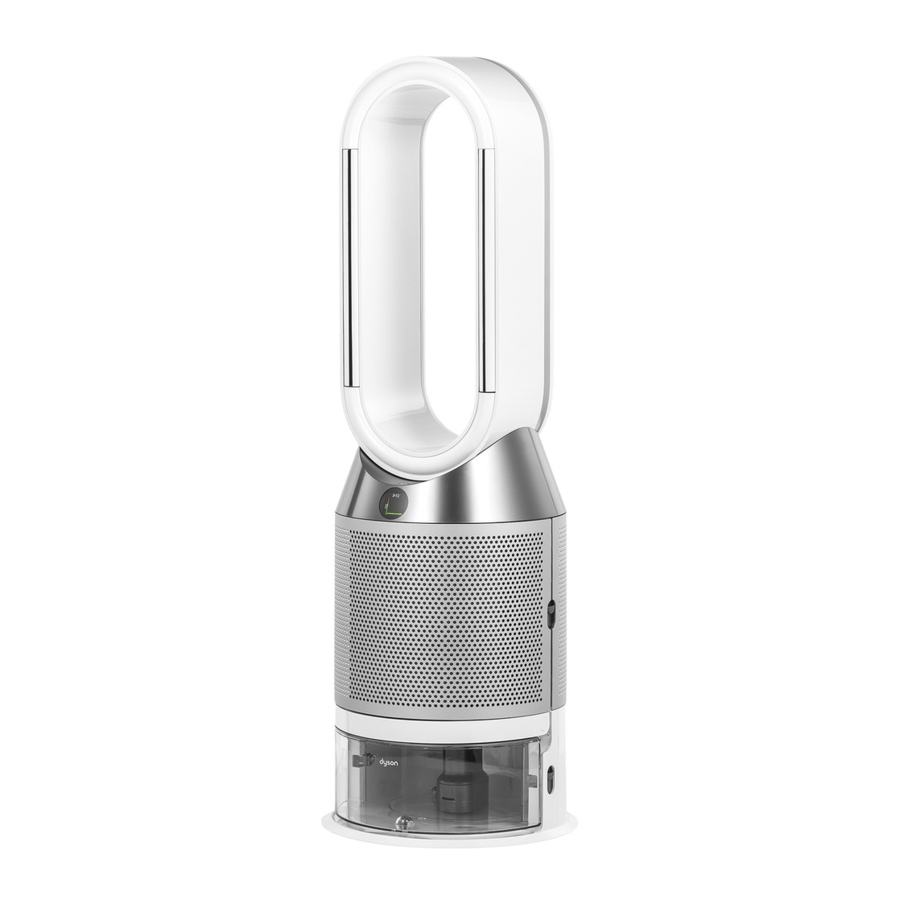
- Очиститель Dyson Hot + Cool
- Поставляется с фильтром HEPA + Carbon.
- Вставьте угольный фильтр HEPA + во внешнюю крышку и установите его на основание. С усилием надавите, пока обе внешние крышки надежно не встанут на место.

Очиститель Dyson Hot + Cool
Поставляется с отдельными HEPA и угольными фильтрами.
Вставьте угольные фильтры на место в машине.
Вставьте HEPA-фильтр во внешнюю крышку. Установите внешние крышки на место на основании и с усилием надавите на них, пока они не защелкнутся.

Очиститель Dyson Hot + Cool Formaldehyde
Ваша машина оснащена постоянным каталитическим фильтром и угольным фильтром HEPA +.
Вставьте каталитический фильтр на место на машине.
Вставьте угольный фильтр HEPA + во внешнюю крышку и установите на основание.
С усилием надавите, пока обе внешние крышки не встанут на место.

Первые шаги

Подключение к приложению Dyson Link
Получите полный контроль с помощью приложения Dyson Link и получите доступ к пошаговой настройке и поддержке, контролируйте, как и когда работает ваш очистительный тепловентилятор Dyson, отслеживайте качество воздуха с помощью визуальных обновлений и автоматически получайте последние обновления программного обеспечения.

Загрузите приложение Dyson Link из App Store или Google Play.
Откройте приложение и следуйте инструкциям на экране, чтобы создать новую учетную запись.

Робот Android воспроизводится или модифицируется из работы, созданной и распространяемой Google и используемой в соответствии с условиями, описанными в Лицензии на атрибуцию Creative Commons 3.0.

Подключение к вашему умному дому
Использование Amazon Alexa
Попросите Алексу включить навык Dyson для управления очистителем или увлажнителем Dyson. И установите процедуру, которая автоматизирует работу вашей машины с другими устройствами в вашем доме.

Использование Google Assistant
Управляйте всеми подключенными очистителями с помощью Google или настройте процедуру для автоматизации работы вашей машины с другими устройствами в вашем доме. Просто скажите «Окей, Google», чтобы начать.

Использование Siri
Подключите свои машины Dyson к ярлыкам Siri, и вы сможете управлять ими с помощью голоса на своем устройстве Apple.

Питание и непрерывный мониторинг
Включение / выключение режима ожидания
Нажмите кнопку включения / выключения режима ожидания на обогревателе с очистительным вентилятором Dyson или на пульте дистанционного управления, чтобы остановить машину. Он продолжит следить за качеством воздуха.
Непрерывный мониторинг
По умолчанию непрерывный мониторинг отключен. После включения он всегда будет активен, пока вы не выключите его снова.
Если включен непрерывный мониторинг, ваш воздухонагреватель Dyson будет собирать информацию о качестве воздуха, температуре и влажности, которая отображается на ЖК-экране и в приложении Dyson Link.
Непрерывный мониторинг
Нажмите и удерживайте кнопку автоматического режима на пульте дистанционного управления в течение 5 секунд, чтобы включить его. На ЖК-экране будет отображаться, когда непрерывный мониторинг включен или выключен.
Wi-Fi подключения
По умолчанию Wi-Fi включен. Чтобы включить или выключить Wi-Fi, нажмите и удерживайте кнопку включения / выключения режима ожидания на устройстве в течение 5 секунд.
 Нажмите эту кнопку, чтобы просмотреть информацию, отслеживаемую вашим тепловентилятором Dyson.
Информация о качестве воздуха, температуре, влажности и уровнях фильтрации отображается на ЖК-экране.
Когда конкретный тип загрязнителя вызывает снижение качества воздуха, на ЖК-экране отображается символ загрязнителя.


Автоматический режим
Установите обогреватель с очистительным вентилятором Dyson в автоматический режим, и встроенные датчики будут грамотно регулировать настройки машины в соответствии с качеством воздуха.
Качество воздуха: ваша машина остановится, когда будет достигнуто целевое качество воздуха, и снова включится, когда уровень качества воздуха упадет.
Скорость воздушного потока: скорость воздушного потока будет увеличиваться до тех пор, пока не будут достигнуты заданные качество и температура воздуха.

Скорость и направление воздушного потока
Нажмите кнопку скорости воздушного потока, чтобы увеличить или уменьшить скорость воздушного потока.
Нажмите кнопку направления воздушного потока, чтобы изменить направление воздушного потока спереди назад.
Измените направление воздушного потока для вашего личного комфорта.
Выберите направление воздушного потока в режим вентилятора для потока воздуха спереди для очистки, охлаждения и нагрева.

осцилляция
Нажмите кнопку «Осцилляция» для циркуляции воздуха по комнате и прокрутите настройки колебаний от 0 ° до 350 °.
Настройте параметры колебаний в приложении Dyson Link.

Ночной режим
В ночном режиме ваш очистительный тепловентилятор Dyson будет продолжать отслеживать изменения качества воздуха и реагировать на них, но только с использованием самых тихих настроек и с затемненным ЖК-экраном.

Таймер сна
Тепловентилятор Dyson автоматически выключится по истечении заданного времени.
Чтобы установить время: нажмите кнопку, чтобы просмотреть варианты времени. После активации нажмите кнопку таймера сна один раз, чтобы увидеть выбранное время.
Чтобы отменить таймер сна: дважды нажмите кнопку таймера сна.

Режимы нагрева и охлаждения
Нажмите кнопку, чтобы установить желаемую температуру в помещении.
Ваша машина остановится, когда будет достигнута установленная температура.
Нажмите кнопку режима охлаждения, чтобы переключить машину из режима нагрева в режим охлаждения.
 Замена угольного фильтра HEPA +
Перед заменой фильтра выключите и отсоедините тепловентилятор очистителя Dyson от сети.
Оставшийся срок службы фильтра отображается на экране и указывает, когда необходимо заменить немоющиеся фильтры. Нажмите кнопку информации на пульте дистанционного управления или проверьте приложение Dyson Link.
Вам нужно будет сбросить срок службы фильтра на вашей машине.
Очиститель Dyson Hot + Cool Поставляется с HEPA + угольным фильтром.
Чтобы заменить угольный фильтр HEPA +, нажмите на кнопки с обеих сторон машины, чтобы освободить внешнюю крышку. Нажмите на выступы, чтобы снять фильтр.
Вставьте сменный фильтр во внешнюю крышку и убедитесь, что выступы встали на место.
Установите внешние крышки на место на машине и с усилием надавите на них, пока они не встанут на место со щелчком.
Подключите и переключите машину, и сбросьте срок службы фильтра.

Сброс срока службы угольного фильтра HEPA +
После замены фильтра важно сбросить срок службы фильтра.
Сброс срока службы угольного фильтра HEPA +
Нажмите и удерживайте кнопку ночного режима на пульте дистанционного управления.
На дисплее вашей машины начнется обратный отсчет от пяти, срок службы фильтра будет сброшен, и ваша машина будет готова к использованию.

Замена HEPA и угольных фильтров
Перед заменой фильтра выключите и отсоедините тепловентилятор очистителя Dyson от сети.
Оставшийся срок службы фильтра отображается на экране и указывает, когда необходимо заменить немоющиеся фильтры. Нажмите кнопку информации на пульте дистанционного управления или проверьте приложение Dyson Link.
Вам нужно будет сбросить срок службы фильтра на вашей машине.

Очиститель Dyson Hot + Cool
Поставляется с отдельными HEPA и угольными фильтрами.
Чтобы заменить фильтр HEPA, нажмите на кнопки с обеих сторон машины, чтобы освободить крышки фильтра. Нажмите на выступы, чтобы снять HEPA-фильтр.
Вставьте сменный фильтр во внешнюю крышку и убедитесь, что выступы встали на место.
Чтобы заменить угольный фильтр в машине, снимите фильтр с основания машины и вставьте новый фильтр.
Установите внешние крышки на место на машине и с усилием надавите на них, пока они не встанут на место со щелчком.
Подключите и переключите машину, и сбросьте срок службы фильтра.
Сброс срока службы HEPA и угольного фильтра
После замены фильтра важно сбросить срок службы фильтра.
Сброс срока службы HEPA-фильтра
Нажмите и удерживайте кнопку ночного режима на пульте дистанционного управления.
На дисплее вашей машины начнется обратный отсчет от пяти, срок службы фильтра будет сброшен, и ваша машина будет готова к использованию.
Сброс срока службы угольного фильтра
Нажмите и удерживайте кнопку осцилляции на пульте дистанционного управления.
На дисплее вашей машины начнется обратный отсчет от пяти, срок службы фильтра будет сброшен, и ваша машина будет готова к использованию.

Замена угольных фильтров HEPA + на каталитический фильтр
Перед заменой фильтра выключите и отсоедините тепловентилятор очистителя Dyson от сети.
Оставшийся срок службы фильтра отображается на экране и указывает, когда необходимо заменить немоющиеся фильтры. Нажмите кнопку информации на пульте дистанционного управления или проверьте приложение Dyson Link.
Вам нужно будет сбросить срок службы фильтра на вашей машине.
Очиститель Dyson Hot + Cool Formaldehyde
Ваша машина оснащена постоянным каталитическим фильтром и угольным фильтром HEPA +.
Вам не нужно менять каталитический фильтр.
Чтобы заменить угольный фильтр HEPA +, нажмите на кнопки с обеих сторон машины, чтобы освободить внешнюю крышку. Нажмите на выступы, чтобы снять фильтр.
Вставьте сменный фильтр во внешнюю крышку и убедитесь, что выступы встали на место.
Установите внешние крышки на место на машине и с усилием надавите на них, пока они не встанут на место со щелчком.
Подключите и переключите машину, и сбросьте срок службы фильтра.

Сброс срока службы угольного фильтра HEPA +
После замены фильтра важно сбросить срок службы фильтра.
Сброс срока службы угольного фильтра HEPA +
Нажмите и удерживайте кнопку ночного режима на пульте дистанционного управления.
На дисплее вашей машины начнется обратный отсчет от пяти, срок службы фильтра будет сброшен, и ваша машина будет готова к использованию.

Уход за вашей машиной
Чтобы ваш обогреватель с очистительным вентилятором Dyson всегда работал с максимальной эффективностью, важно регулярно чистить его и проверять на наличие засоров.
Очистка вашей машины
Если ваша машина пыльная, протрите ее рекламой.amp безворсовая ткань.
Ищите засоры в отверстиях для впуска воздуха на фильтре и небольшом отверстии внутри петли. ampпожизненнее.
Используйте мягкую щетку для удаления пыли и мусора.
Не используйте моющие средства или полироли для чистки машины.
коды ошибок
Если на вашем компьютере отображается код ошибки, попробуйте выключить его, а затем снова включить.
Если код ошибки не сбрасывается, обратитесь в службу поддержки Dyson.
Для получения дополнительной информации и поддержки для вашей машины перейдите в приложение Dyson Link или онлайн: www.dyson.com/support
Документы / Ресурсы
07.11.2022
Просмотров:
669
1.
— Какую воду заливать в увлажнитель?
— Мы рекомендуем использовать фильтрованную, либо дистиллированную воду.
2.
— Что такое f5?
— Ошибка F5 на увлажнителе Dyson AM10 возникает при неисправности двигателя:
- Переведите устройство в режим ожидания или выключите его.
- Отсоедините устройство от электрической сети.
- Подождите 30 секунд.
- Затем снова подключите устройство к сети и включите его.
- Если ошибка повторится, обратитесь в Сервисный центр.
3.
— Сколько весит увлажнитель Дайсон АМ10?
— Вес увлажнителя AM10 составляет — 3,4 кг.
4.
— На какую площадь в среднем рассчитан этот увлажнитель?
— Мы не указываем конкретный метраж, поскольку на эффективность работы увлажнителя воздуха влияет очень много внешних факторов. Среди них: высота потолков, количество отопительных приборов в помещении, материал полов и мебели, количество предметов интерьера (мягкой и корпусной мебели), вентилируемость помещения и многое другое. В лабораториях производителя увлажнитель был протестирован в условиях помещения площадью 16 квадратных метров и относительной влажностью воздуха — 30%. За полчаса он увеличил этот показатель в помещении до 45%.
5.
— Должна ли быть подсветка при работе прибора?
— Да, при работе увлажнителя на передней панели светится синий индикатор. При работе вентилятора светится белый индикатор.
6.
— Хотел спросить почему не идет водная дымка в процессе увлажнения?
— Видимость водяной дымки зависит от установленного целевого значения влажности в помещении, и не влияет на качество работы устройства. Для того, чтобы понимать, корректно ли работает устройство, обратите внимание на уровень воды в баке, в режиме увлажнения она должна убывать.
7.
— У данного устройства АМ10 имеется функция мойка воздуха?
— Данная модель не оснащена функцией очистки воздуха. В актуальном модельном ряду представлены увлажнители-очистители. Вы можете ознакомиться с ними по ссылке: https://shop-dyson.kz/ochistiteteli-uvlazhniteli-vozduxa/
8.
— Что значит режим вентилятора? Увлажнитель Dyson AM10 может работать как отдельное устройство-вентилятор, без какого либо увлажнения?
— Да, именно так. Обычно, в летнее время, когда не требуется увлажнение воздуха и жарко, этот прибор служит вентилятором.
9.
— Меня вот интересует на сколько может хватать 3 литра воды?
— Расход воды в режиме увлажнения составляет 300 мл/ч – резервуара объемом 3 литра достаточно для 10 часов работы. Обращаем ваше внимание, что увлажнитель Dyson AM10 показывает на корпусе уровень относительной влажности в помещении. Необходимый уровень относительной влажность можно выбрать вручную (до 70%) или установить автоматический режим, в котором уровень относительной влажности составляет 40-50%. При этом 3 литра объема резервуара для воды рассчитаны на использование изделия непрерывно до 18 часов.
10.
— Как понять что функция увлажнения работает корректно? Приобрели увлажнитель, но почему-то уровень влажности не меняется до нужного уровня.
— Как правило, при использовании в течение первых нескольких недель, основной объем водяного пара поглощается предметами в самом помещении, например, деревянной мебелью и полами. После этого увлажнитель концентрируется только на воздухе.
Повысить скорость увлажнения помещения и максимальный уровень влажности, поддерживаемый устройством, вы можете на пульте дистанционного управления вручную. На скорость достижения целевого уровня влажности также влияет выбранная скорость воздушного потока: чем она выше, тем быстрее происходит циркуляция насыщенного влагой воздуха в помещении.
Рекомендуем ориентироваться на расход воды в баке при использовании, если она убывает, то устройство работает корректно.
11.
— Как ухаживать за увлажнителем Dyson AM10?
— Для корректного функционирования вашего устройства рекомендуется производить его очистку согласно инструкции:
(1) Перед очисткой переведите устройство в режим ожидания или выключите.
Отключите устройство от источника электропитания.
Протрите контурный усилитель (овальное кольцо, из которого выходит дымка).
Обратите особое внимание на воздушные зазоры, их необходимо протереть безворсовой микроволокнистой тканью.
Эту процедуру необходимо производить не реже 1 раза в неделю.
(2) Также не реже 1 раза в месяц необходимо отсоединять рамку (переднюю часть) контурного усилителя, так как в ней может скапливаться конденсат. После этого нужно удалить капли воды сухой тканью. Чтобы отсоединить переднюю рамку контурного усилителя необходимо аккуратно, но с усилием потянуть за её нижнюю часть со стороны выступа и отсоединить со всех сторон от овальной части корпуса.
(3) Для того чтобы произвести очистку резервуара для воды:
Подготовьте раствор лимонной кислоты и воды (30 грамм на 1 литр воды).
Залейте рекомендуемый раствор лимонной кислоты и воды в резервуар.
Установите на место крышку и встряхивайте контейнер в течение 30 секунд.
Затем оставьте постоять и через 15 минут опорожните контейнер.
Процедуру необходимо производить не реже 1 раза в месяц.
При возникновении вопросов, касающихся техники Dyson, рекомендуем обращаться в Фирменный сервис центр по номеру: +7 771 504 68 94
- Manuals
- Brands
- Dyson Manuals
- Air Cleaner
- PH01
- Service instructions manual
-
Contents
-
Table of Contents
-
Bookmarks
Quick Links
Questo manuale d’istruzione è fornito da trovaprezzi.it. Scopri tutte le offerte per
Dyson Pure Humidify +
Cool
o cerca il tuo prodotto tra le
migliori offerte di Trattamento Aria
Issued December 19
Related Manuals for Dyson PH01
Summary of Contents for Dyson PH01
-
Page 1
Questo manuale d’istruzione è fornito da trovaprezzi.it. Scopri tutte le offerte per Dyson Pure Humidify + Cool o cerca il tuo prodotto tra le migliori offerte di Trattamento Aria Issued December 19… -
Page 2: Table Of Contents
This manual is written specifically for Dyson trained engineers and covers the full Circulates PH01 and PH02 range. The service instructions assume that the engineer has the approved Air Multiplier technology projects 350 litres of air per second, tools and test equipment with them.
-
Page 3: Product Overview Features And Benefits
HEPA filter to capture 99.95% of ultra fine particles. 4. Wrong Power Supply Unit (PSU) inserted/PSU fault PH01 machine comes with Combination filters. PH02 comes with permanent Cryptomic filters and Combination filters.
-
Page 4: Technical Information
Faults codes will be displayed as per the following format: 00X-0X-0X-X. As well as the UI error symbols, built into PH01 and PH02’s software is an engineers diagnostic In most cases it is only necessary to recognise the first three digits to determine the fault.
-
Page 5: Deep Cleaning The Machine
Deep cleaning the machine PH01 and PH02 have a ‘self cleaning’ cycle built in. This is to reduce limescale build up. In normal use the machine will show an alert when it needs to carry out a Deep clean cycle.
-
Page 6: Testing And Repair Process
General information Electrical safety testing The following tests must be performed prior to and upon completion of all repairs to Dyson products and before any functional checks. You must ensure that a full visual inspection of the product is completed prior to repair.
-
Page 7: Amp Service Assembly — Removal
Repair notes AMP Service Assembly — removal 01 Press the release catches on either side of the filter housings. Remove the filter Housing and Filter assemblies from the product. 04 Carefully lift off the Amp service Note: if the product is a Cryptomic assembly.
-
Page 8
For removal instructions of these parts continue to the next step. Note: not all PCBs are available as spare parts at launch. Always check Dyson Central for 08 To remove the Power button, lever out the two arms and push out the Button, spring and Foam. -
Page 9
09 Push the three grommets through the 12 Remove the Four T-15 screws. neck plate. 13 Release two of the three looms from 10 Remove the six T-8 screws. the large Grommet. 14 Carefully push the large single grommet through the hole in the 11 Remove the plate from the AMP neck assembly. -
Page 10: Amp Service Assembly — Fitting
Repair notes AMP Service Assembly — fitting If the Air Amp Neck Service assembly was previously removed, continue to the next step. If the reason for the repair is to replace the entire Amp Service assembly go to page 20 step 23 — 30. 15 Carefully feed the Grommets 16 Feed the three looms through the and looms through the AMP neck…
-
Page 11
21 Seat the three grommets into the 18 Fit the four T-15 screws. neck plate. 19 Feed the three looms through the neck plate. 22 Locate the foam ring and then the spring into the AMP neck assembly. Ensure the On/Off button is orientated the correct way up. Push the On/Off Button Service assembly 20 Fit the six T-8 screws. -
Page 12
24 Secure the Dust sensor to main controller loom into the retainers provided. 23 Carefully attach the Dust sensor to main controller loom. Locate the Dust Sensor and Dust sensor PCB Service assembly. 25 Reconnect the four Looms. Fit the two long T-8 screws. -
Page 13
26 Secure all Looms into the retainers provided. 27 Line up the LCD with the window on the Neck Service assembly. 28 Fit the eight T-15 screws. Lower the Air Amp Service assembly. -
Page 14: Lower Body Service Assembly — Removal
Repair notes Lower Body Service Assembly — removal Before continuing the following components will need to be removed as previously shown: Air amp service assembly (Pages 10 — 11, steps 01 — 05) 29 Refit the Evaporator assembly. 31 Remove the Water tank. 32 Remove the two T-8 screws in the top of the Filter release catch service assembly.
-
Page 15
37 If the Evaporator door needs replacing, remove the two screws in the top hinge cover and remove the 34 Disconnect the Power loom from the cover. Power controller PCB. 35 Remove the two T-15 screws on the right handside from behind the filter release catch holding at the base. -
Page 16
40 To refit the hinge covers, shut the door. Slide the cover from behind 41 Remove the two T-15 screws. the hinge so the lever folds back into the cover. 42 Remove the two T-8 screws from the Slide the cover forward until the screw underside of the Lower body service bosses line up. -
Page 17: Lower Body Service Assembly — Fitting
Repair notes Lower Body Service Assembly — fitting 44 Release the Power loom from the retainers in the side of the Main body. 45 Lift the Main body away from the 46 Place the Main body on top of the Lower Body Service assembly. Lower body service assembly.
-
Page 18
49 To refit the hinge covers, shut the door. Slide the cover from behind the hinge so the lever folds back into the cover. 48 Fit the two T-8 screws in the underside of the Lower body, and the four T-15 screws to secure the Main body to the Lower Body. -
Page 19
50 Feed the power loom through the hole in the top right hand side of the main body. 53 Ensure the power loom is positioned as shown to avoid trapping. 54 Slide the bottom of the Filter release catch into the details in the Main 51 Connect the Main power loom to the body. -
Page 20: Motor And Bucket Service Assembly — Removal
Repair notes Motor and Bucket Service Assembly — removal Before continuing the following components will need to be removed as previously shown: Air amp service assembly (Pages 10 — 11, steps 01 — 05) 59 Feed the Grommet and connector 56 Disconnect the Motor loom from the Main PCB assembly.
-
Page 21
62 With all three clips released the motor bucket can be removed. Carefully lift the motor bucket up and away from the Main body. 61 Using a blunt screwdriver carefully push the three tabs securing the Motor and Bucket assembly inside the Main body. -
Page 22: Motor And Bucket Service Assembly — Fitting
Repair notes Motor and Bucket Service Assembly — fitting Cross section view of Upper retention ring and spring positions Important: during shipping/transport the Upper, Lower retention rings and springs can detach. Before fitting the Motor and bucket assembly the Upper and Lower Spring retention rings have to be seated on their corresponding ledges on the motor bucket…
-
Page 23
66 Feed the motor loom connector through the hole in the Main body. 65 Push the Motor down until three clicks are heard. 67 Securely seat the motor loom grommet into the hole in the main body. 68 Connect the new motor to the Main PCB. -
Page 24: Connection Shuttle Service Assembly — Removal
Repair notes Connection Shuttle Service Assembly — removal Before continuing the following components will need to be removed as previously shown: Air amp service assembly (Pages 10 — 11, steps 01 — 05) Lower Body Service assembly (page 25 — 30, steps 31 — 35). 70 Remove the Tray Level Harness assembly.
-
Page 25: Connection Shuttle Service Assembly — Fitting
Repair notes Connection Shuttle Service Assembly — fitting 76 Slide the new Connection Shuttle Service assembly into place ensuring all the looms are free from trapping 73 Remove the six T-8 screws holding the tray to the Main body. and no seals have folded over. 74 Disconnect the Shuttle Loom from the Power controller PCB and release the loom from the retainers in the side of…
-
Page 26
79 Position the Connection Shuttle as shown and test it slides freely. 80 Locate the Shuttle Spring and Shuttle Spring Spigot into the hole in the rear of the Connection Shuttle. 78 Firmly locate the two rails on the base of the Water return tray onto the details on the Connection 81 Hold the Spigot firmly whilst carefully Shuttle. -
Page 27: Internal Power Harness Service Assembly — Removal
Repair notes Internal Power Harness Service Assembly — removal Before continuing the following components will need to be removed as previously shown: Air amp service assembly (Pages 10 — 11, steps 01 — 05) Lower Body Service assembly (page 25 — 30, steps 31 — 35). 82 Locate the tray level sensor into the 85 Remove the two T-8 screws holding water return tray.
-
Page 28
88 Unclip the retaing detail at the end of 91 Remove the two T-8 screws securing the skirt from the base. the Socket holder. 89 Remove the two countersunk T-8 92 Remove the Holder and Power screws holding the Base plate. harness. -
Page 29: Internal Power Harness Service Assembly — Fitting
Repair notes Internal Power Harness Service Assembly — fitting 97 Pull the Jack into the holder until it 94 Feed the new Power Harness locks and is flush with the edge as through the right handside of the shown. Lower Body Service assembly. 98 Seat the front of the holder into the 95 Locate the gasket into the hole in the Lower body.
-
Page 30
101 Place the Base plate onto the Lower body. Fit the two countersunk T-8 screws. 99 Press the holder down and fit the two T-8 screws. IMPORTANT: whilst tightening the screws check that the gasket does not become mishapen or the DC Jack misplaced. -
Page 31: Parts Diagram Main Body
Parts diagram Main body Motor Bucket Seal Tail Cone Motor & Bucket Service Assy Tray Level Sensor Assy Internal Input Harness Service Assy Clean Cycle PCB Assy 103 Run the left handside of the Base LCD Display Service Assy Skirt anti-clockwise aroun the base. Clip the securing tab in the base.
-
Page 32: Amp And Filter Assemblies
Parts diagram Amp and Filter assemblies Screw M3x15-P1 Remote Control Assy Air Amp Neck Service Assy Dust Sensor Assy Filter Housing Singular Glass Hepa & Inner Carbon Filter MO…
This manual is also suitable for:
Ph02
Technical infomation
Accessing the diagnostic menu
Diagnostic menu
As well as the UI error symbols, built into PH01 and PH02’s software is an engineers diagnostic
menu designed to enable the repair agent a quickly diagnosis of the machines failure.
The menu is accessed by pressing a sequence of buttons via a standard remote control.
2
1
AUTO
Switch
Press night mode
machine on.
button once.
4
5
AUTO
Engineering screen
will appear.
Immediately press
the oscillation
button once.
Once you have finished accssing the engineering menu, press any button on the remote except
the ‘i’ button to exit the diagnostic menu.
If the engineering screen does not appear press any button to reset and start again.
Repeat all steps ensuring the flow button is pressed between 11 and 13 seconds detailed in
step 3.
4
3
AUTO
AUTO
Hold down flow
mode direction
button for 11 to
13 seconds.
6
AUTO
Press i button six times to show
fault code screen
(the screen above is an
example).
04
Technical infomation
Diagnostic table
Faults codes will be displayed as per the following format: 00X-0X-0X-X.
In most cases it is only necessary to recognise the first three digits to determine the fault.
Fault code
Any codes starting with 002
Motor and Bucket assembly
except 002-02-01-2
002-02-01-2
AMP assembly
Any codes starting with 003
Main PCB assembly
Any codes starting with 004
LCD display service assembly or
Main PCB assembly
Any codes starting with 005
Main PCB assembly
Any codes starting with 006
Main PCB assembly
Any codes starting with 007
Power supply unit, DC inlet assembly or Main PCB assembly
Any codes starting with 008
Dust sensor service assembly or
Sensor input service assembly or
Sensor PCB service assembly
Any codes starting with 009
Wifi PCB*, Wifi harness assembly, Heater PCB, Heater har-
except 009-01-01-1 and
ness or Humidifier PCB
009-01-02-1
009-01-01-1
Motor and Bucket assembly
009-01-02-1
Any codes starting with 010
Main PCB assembly
Any codes starting with 011
Humidifier PCB, AMP assembly, Evaporator tray sensor, Water
tank harness or Pump column
*The Wifi PCB is a non-replaceable part.
Affected Part/s
05
Go to dyson
[MEGATHREAD] Dyson PH01 «water tank empty» issues and disassembly.
Hello everyone,
A few days ago I promised another poster that I would take a look at the PH01 humidify cool tank and lid assembly to try and diagnose what the failure point of the machine is and why so many of us either get poor humidification or the machine flat out refuses to recognize there’s water.
So I began the process but have been busy with other things, in this thread I’ll be documenting everything that I see during the process and attempting a repair(if possible) to make the tank and assembly that goes in water…not fail when it touches water.
You can find the first part of my examination along with pictures here: https://imgur.com/a/8BwpdZ8
And I will be posting more in the coming days hopefully. So far, I can say that I am extremely disappointed with how the lid assembly is put together and for a $1000 machine, a lot of poor design choices were made from casual observation. By the way, you will see that the main housing for all of our electronics, the «brain» so to speak of the water tank to the machine, is covered with a simple thin plastic piece smaller than a credit card, covered with duct tape…yes, duct tape and water pools on the interior of the lid as well leading to corrosion.
So yeah, complete mess so far. Stay tuned for updates!
Edit: here is part 2(https://imgur.com/a/41LjWdu) and the last part. I’m sorry to report that despite my efforts, the machine is still exhibiting the same issue, read on for why. So here’s the story of all that I noticed and dealt with(there are some notes on the pictures as well):
-
The quality of the parts…just…as I said before, this is my first Dyson product and I’ve been hearing about them for ages as being amazing quality; this is in no way what I expected. The plastic is cheap beyond measure and I had to be very gentle removing pieces because they would twist and want to deform very easily.
-
The most crucial part of the whole system, the chamber where the main logic board sits is just an embarrassment of engineering. I understand cost cutting and budgets, but *duct tape?!* and it got worse when I actually got inside the chamber. Now I know why Dyson sent out an email to some owners about being extra careful with the lid and not tilting it in any way when refilling the tank. The duct tape «works» to keep water out, but if you get water anywhere near the connectors, there are literally ZERO seals or anything to keep water from pooling on top of the duct tape and seeping into the chamber.
-
The mainboard. I don’t know what they made it out of, but I’ve dealt with all kinds of boards from all kinds of products and it is only this machine in all my years, that has such a cheap, cheap, cheap quality to it.
-
The wires are the thinnest gauge you can imagine and the connecting prongs feel like they could snap at any moment when handled. Again, poor quality.
So what’s the problem exactly? Well here’s what my examination revelated. The primary logic board is just *dead*, flat out. I took everything a part, scrubbed with a toothbrush/q-tips and cleaned everything with 70% alcohol, then 99% to remove any excess water and finally compressed air after 4 hours of drying time just to make sure there was no moisture anywhere in the assembly. I put it all back together and fired up the PH01 and the same issue persisted. I then realized I should have tested the board for continuity and checked that, but there was none. So unfortunately, it seems that a machine designed for being in the presence of water, has such low tolerance for water that the water that collects in the chamber just kills it, I’m fairly confident it’s a short circuiting issue where when the tank is filled up and any water enters the holes at the top, it immediately pools into the circuit board chamber and while this may work a few times, eventually when you reconnect the tank to the machine and an electrical current flows from the prongs into the board steeped in water, ruining it in the process. This also means that if you place the lid assembly upside down at any point, any remaining water will just run down the central chamber, into the lid and right past our quality duct tape and into the chamber.
It is no wonder that so many of us have issues with it and feel like we’re going crazy. Even if you *don’t* get any water on the prongs and they look perfectly fine, the connectors are fine, etc; the problem is that there is no longer any communication between the main machine and the smaller logic board inside the lid assembly. No, you’re not crazy. There’s water in the tank, but you have no means of telling the machine that. I would argue that the machine itself is «okay» in terms of reliability, but the tank assembly is the worse part of the whole design.
The best way to have done this if they wanted to be this cheap, was to have the lid assembly be a part of the main machine, and the only thing the end user actually took out, was just the water tank itself and then slid that back in when filled. It is utterly baffling that they signed off on such a design.
Take away:
-
Do not ever, ever place the lid upside down, angle it, splash water or shake the lid. Once the water gets in, the only place it can go is into the chamber where the main board resides. If your machine dies and they send a replacement, either disassemble the lid assembly right away and apply waterproof sealant to the plastic lid under the duct tape or just sell the replacement and buy a separate air purifier and humidifier. Additionally, you could buy stock in duct tape.
Specifications:1834/1834454-ph01.pdf file (13 Jun 2023) |
Accompanying Data:
Dyson PH01 Air Cleaner PDF Service Instructions Manual (Updated: Tuesday 13th of June 2023 04:35:29 PM)
Rating: 4.4 (rated by 49 users)
Compatible devices: purehot+cool link, pure hot+cool, Pure Hot + Cool, Pure Cool, pure cool link tower, TP02, Pure Cool DP04, Pure Hot+Cool HP00.
Recommended Documentation:
Text Version of Dyson PH01 Service Instructions Manual
(Ocr-Read Summary of Contents, UPD: 13 June 2023)
-
1, Dyson PH01 Issued December 19 Questo manuale d’istruzione è fornito da trovaprezzi.it. Scopri tutte le offerte per Dyson Pure Humidify + Cool o cerca il tuo prodotto tra le migliori offerte di Trattamento Aria
… -
31, Dyson PH01 103 Run the left handside of the Base Skirt anti-clockwise aroun the base. Clip the securing tab in the base. 104 Run the right handside of the Base Skirt clockwise aroun the base. Clip the securing tab in the base. 105 Fit the Two T-8 screws. 58 After fitting the harness, continuing fitting the followi…
-
27, 82 Locate the tray level sensor into the water return tray. 83 Retain the Tray level sensor harness into all the details provided and feed through the top of the Main body. 84 Retain the Shuttle Harness into all details provided and feed through the top of the Main body. 50 After fitting the harness,…
-
3, 01 Product overview Features and benefits 02 03 Product overview Display error symbols Captures gases and ultra fine particles The sealed filtration system combines an activates carbon filter to remove gases and a sealed HEPA filter to capture 99.95% of ultra f…
-
22, Repair notes Motor and Bucket Service Assembly — fitting 63 Important: ensure both the Upper and Lower retention rings and all six tension springs are located correctly around the top and bottom of the motor bucket assembly. Failure to do so will result in a failed repair. Top…
-
32, Parts diagram Amp and Filter assemblies Remote Control Assy Air Amp Neck Service Assy Dust Sensor Assy Glass Hepa & Inner Carbon Filter MO Filter Housing Singular Screw M3x15-P1 60
… -
12, 11 20 23 Carefully attach the Dust sensor to main controller loom. Locate the Dust Sensor and Dust sensor PCB Service assembly. Fit the two long T-8 screws. 25 Reconnect the four Looms. 21 24 Secure the Dust sensor to main controller loom into the retainers provided.
… -
16, 40 To refit the hinge covers, shut the door. Slide the cover from behind the hinge so the lever folds back into the cover. Fit the two T-8 screws into the Hinge cover. Slide the cover forward until the screw bosses line up. 28 41 Remove the two T-15 screws. 42 Remove the two T-8 screws…
-
29, Repair notes Internal Power Harness Service Assembly — fitting 94 Feed the new Power Harness through the right handside of the Lower Body Service assembly. 96 Locate the Harness through the opening in the top of the holder. 95 Locate the gask…
-
2, Dyson PH01 Technical information Accessing the Diagnostic menu………………………………………………………………………..04 Diagnostic table …………………………………………………………………………………………..05 Deep cleaning the machine ………………………..…
-
24, 69 Fit the Motor to AMP seal. Ensure it is the correct way up and seated around the top of the Motor bucket. 44 After fitting the seal, continuing fitting the following components as previously shown: Air AMP Service assembly (Page 21 — 24, steps 25 — 30) 70 Remove the Tray Level Harness assembly. If …
-
Dyson PH01 User Manual
-
Dyson PH01 User Guide
-
Dyson PH01 PDF Manual
-
Dyson PH01 Owner’s Manuals
Recommended Instructions: PX-W2410TU, VMW 100, 6820 — Cell Phone — GSM


-
Samsung TH026EAV
INSTALLATION MANUALMANUAL DE INSTALACIÓNMANUEL D’INSTALLATIONMANUALE D’INSTALLZIONEMANUAL DE INSTALAÇÃOINSTALLATIONS-HANDBUCHΕΓΧΕΙΡΙΔΙΟ ΕΓΚΑΤΑΣΤΑΣΗΣ ИНСТРУКЦИЯ ПОЛЬЗОВАТЕЛЯ System Air Conditioner (Cooling and Heating)Aire acondicionado sistemático (Enfriamiento y Calefacción)Climatiseur numérique multifonctionnel (Réfrigération & Chauffag …
TH026EAV 24
-
Levoit Core 300
True HEPA Air PurifierProduct Series: Core 300Models: Core 300, Core 300-RACUSER MANUALQuestions or Concerns?Please contact us Mon–Fri, 9:00 am–5:00 pm PST/PDTat [email protected] or at (888) 726-8520. …
Core 300 20
-
vollara CLASSIC AIR
CAUTION: Read manual carefully for proper procedures and operation.USER’S MANUAL100, 110, and 220 Volt SystemsInstallation | Operation | Specifications | WarrantyCLASSICAIRELECTRONIC AIR PURIFICATION …
CLASSIC AIR 12
Popular Right Now:
Operating Impressions, Questions and Answers: