BCM DTC Chart
| DTC | Description | Action |
|---|---|---|
| B1182:00 | Tire Pressure Monitoring System: No Sub Type Information | GO to Pinpoint Test A |
| B1182:55 | Tire Pressure Monitoring System: Not Configured |
|
| B124D:02 | Tire Pressure Sensor: General Signal Failure | GO to Pinpoint Test E |
B1182:00
Normal Operations and Fault Conditions
REFER to: Tire Pressure Monitoring System (TPMS) — System Operation and Component Description (204-04B Tire Pressure Monitoring System (TPMS), Description and Operation).
Communication between the RTM and the TPMS sensors can be interrupted by Radio Frequency Interference (RFI), which causes intermittent issues that are not vehicle concerns. Radio Frequency Interference (RFI) is generated by electrical motors and appliance operation, cellular telephones, remote transmitters, power inverters and portable entertainment equipment.
DTC Fault Trigger Conditions
| DTC | Description | Fault Trigger Conditions |
|---|---|---|
| B1182:00 | Tire Pressure Monitoring System (TPMS): No Sub Type Information | Set by the BCM in continuous memory when all 4 of the tire pressure sensors are faulted, not communicating with the RTM or when sensor data is not received by the BCM from the RTM. |
Possible Sources
- Radio Frequency Interference (RFI)
- RTM communication concern
- TPMS sensor(s)
- GWM
- BCM
Visual Inspection and Diagnostic Pre-checks
- Inspect for cell phone chargers or GPS units.
- Inspect for Non-Original Equipment Manufacturer (OEM) wheels or run-flat tires.
- Verify horn operation.
- Verify spare tire is not in use.
NOTE: Make sure all aftermarket electronic equipment has been disconnected (if possible) and the customer has been questioned about the electronic equipment they may have been using in the vehicle when this concern was identified.
| A1 CHECK FOR COMMUNICATION WITH THE GWM (GATEWAY MODULE A) , THE RTM (RADIO TRANSCEIVER MODULE) AND THE BCM (BODY CONTROL MODULE) | ||||
Does the GWM, the RTM and the BCM all pass the Network Test?
|
||||
| A2 CHECK FOR RTM (RADIO TRANSCEIVER MODULE) DIAGNOSTIC TROUBLE CODES (DTCS) | ||||
Are any Diagnostic Trouble Codes (DTCs) present in the RTM?
|
||||
| A3 CHECK THE BCM (BODY CONTROL MODULE) TPMS (TIRE PRESSURE MONITORING SYSTEM) STATUS (TPMS_STATUS) PID (PARAMETER IDENTIFICATION) | ||||
Does the TPMS_STATUS PID display SYSTEM FAULT?
|
||||
| A4 CARRY OUT THE TPMS (TIRE PRESSURE MONITORING SYSTEM) SENSOR TRAINING PROCEDURE | ||||
Did all of the TPMS sensors train and did the horn sound when each sensor was trained?
|
||||
| A5 REPEAT THE TPMS (TIRE PRESSURE MONITORING SYSTEM) TRAINING | ||||
Did any of the TPMS sensors train and did the horn sound when each sensor was trained?
|
||||
| A6 CHECK FOR CORRECT BCM (BODY CONTROL MODULE) OPERATION | ||||
Is the concern still present?
|
B124D:02
Normal Operation and Fault Conditions
REFER to: Tire Pressure Monitoring System (TPMS) — System Operation and Component Description (204-04B Tire Pressure Monitoring System (TPMS), Description and Operation).
Communication between the RTM and the TPMS sensors can be interrupted by Radio Frequency Interference (RFI), which causes intermittent issues that are not vehicle concerns. Radio Frequency Interference (RFI) is generated by electrical motors and appliance operation, cellular telephones, remote transmitters, power inverters and portable entertainment equipment.
DTC Fault Trigger Conditions
| DTC | Description | Fault Trigger Conditions |
|---|---|---|
| B124D:02 | Tire Pressure Sensor: General Signal Failure | Set by the BCM in continuous memory when 1, 2 or 3 of the tire pressure sensors are faulted, not communicating with the RTM or when sensor data is not received by theBCM from the RTM. |
Possible Sources
- Radio Frequency Interference (RFI)
- One or more TPMS sensors not trained
- TPMS sensor(s)
Visual Inspection and Diagnostic Pre-checks
- Inspect for customer electronic devices, such as cell phone chargers or GPS units.
- Inspect for Non-Original Equipment Manufacturer (OEM) wheels or run-flat tires.
- Verify horn operation.
- Verify spare tire is not in use.
| B1 CHECK THE BCM (BODY CONTROL MODULE) TPMS (TIRE PRESSURE MONITORING SYSTEM) STATUS (TPMS_STATUS) PID (PARAMETER IDENTIFICATION) AND SENSOR IDENTIFIERS | ||||||||||||||||||||||||||||||||||||||||||||||
Does the BCM TPMS_STATUS PID display SENSOR FAULT?
|
||||||||||||||||||||||||||||||||||||||||||||||
| B2 CARRY OUT THE TPMS (TIRE PRESSURE MONITORING SYSTEM) SENSOR TRAINING PROCEDURE | ||||||||||||||||||||||||||||||||||||||||||||||
Did all of the TPMS sensors train and did the horn sound when each sensor was trained?
|
||||||||||||||||||||||||||||||||||||||||||||||
| B3 ATTEMPT TO TRAIN THE TPMS (TIRE PRESSURE MONITORING SYSTEM) SENSORS AGAIN | ||||||||||||||||||||||||||||||||||||||||||||||
Did any of the TPMS sensors train and did the horn sound when each sensor was trained?
|
||||||||||||||||||||||||||||||||||||||||||||||
| B4 CHECK FOR CORRECT BCM (BODY CONTROL MODULE) OPERATION | ||||||||||||||||||||||||||||||||||||||||||||||
Is the concern still present?
DTC Fault Trigger Conditions
Possible Sources
Visual Inspection and Diagnostic Pre-checks
|
Изменено 7 Ноября 2016 пользователем KillBill
В общем я понял так:
что надо заново обучить блок TPM наличию датчиков давления.
Для этого надо:
1.Поверните выключатель зажигания в положение off,
2.затем нажмите и отпустите педаль тормоза.
3.Поверните замок зажигания из положение off в положение Run 3 раза, закончив в положении «Run».
4.Нажмите и отпустите педаль тормоза.
5.Поверните выключатель зажигания в положение off.
6.Поверните переключатель зажигания из положение off в положение Run 3 раза, закончив в положении «Run».
Рог будет звучать один раз и индикатор СКДШ будет мигать в случае, если режим тренировки были успешно внесены.
На приборке появится сообщение, о переходе к обучению датчиков.
Примечание: это может занять до 6 секунд, чтобы активировать датчик давления в шинах.
Для активации контроля давления в шинах должен быть инструмент чем нажать на клапан соска в шине.
7.Нажмите и отпустите кнопку теста на приборной панели, для активации контроля давления в шинах.
Рог будет кратко звук, чтобы указать, что датчик давления в шинах была признана ВСМ .
В течение 2 минут звучания клаксона, нажмите на клапан соска на 6 сек.
Примечание: не ждать более 2 минут между обучением каждого датчика, иначе придётся всю процедуру повторить.
Повторите шаг 7 для каждой шины
Процедура будет завершена после обучения последнего датчика и об этом будет сообщение на дисплее.
И вот не совсем понятно с моментом нажатия клапана соска.
Может кто поточнее перенвести этот фрагмент?
:The horn will sound once and the TPMS indicator will flash if the training mode has been entered successfully. If equipped, the message center will display TRAIN LF TIRE.
NOTE: It may take up to 6 seconds to activate a tire pressure sensor. During this time, the Tire Pressure Monitor Activation Tool must remain in place at the valve stem.
Place the Tire Pressure Monitor Activation Tool on the LF tire sidewall at the valve stem. Press and release the test button on the Tire Pressure Monitor Activation Tool. The horn will sound briefly to indicate that the tire pressure sensor has been recognized by the BCM .
Within 2 minutes of the horn sounding, place the Tire Pressure Monitor Activation Tool on the RF tire sidewall at the valve stem and press and release the test button to train the RF tire pressure sensor.
NOTE: Do not wait more than 2 minutes between training each sensor or the BCM will time out and the entire procedure must be repeated.
Repeat Step 7 for the RR and LR tires.
The procedure is completed after the last tire has been trained. When the training procedure is complete, the message center (if equipped) will display TIRE TRAINING COMPLETE.
Изменено 19 мая 2017 пользователем sovg
BCM DTC Chart
| DTC | Description | Action |
|---|---|---|
| B1182:00 | Tire Pressure Monitoring System: No Sub Type Information | GO to Pinpoint Test A |
| B1182:55 | Tire Pressure Monitoring System: Not Configured |
|
| B124D:02 | Tire Pressure Sensor: General Signal Failure | GO to Pinpoint Test E |
B1182:00
Normal Operations and Fault Conditions
REFER to: Tire Pressure Monitoring System (TPMS) — System Operation and Component Description (204-04B Tire Pressure Monitoring System (TPMS), Description and Operation).
Communication between the RTM and the TPMS sensors can be interrupted by Radio Frequency Interference (RFI), which causes intermittent issues that are not vehicle concerns. Radio Frequency Interference (RFI) is generated by electrical motors and appliance operation, cellular telephones, remote transmitters, power inverters and portable entertainment equipment.
DTC Fault Trigger Conditions
| DTC | Description | Fault Trigger Conditions |
|---|---|---|
| B1182:00 | Tire Pressure Monitoring System (TPMS): No Sub Type Information | Set by the BCM in continuous memory when all 4 of the tire pressure sensors are faulted, not communicating with the RTM or when sensor data is not received by the BCM from the RTM. |
Possible Sources
- Radio Frequency Interference (RFI)
- RTM communication concern
- TPMS sensor(s)
- GWM
- BCM
Visual Inspection and Diagnostic Pre-checks
- Inspect for cell phone chargers or GPS units.
- Inspect for Non-Original Equipment Manufacturer (OEM) wheels or run-flat tires.
- Verify horn operation.
- Verify spare tire is not in use.
NOTE: Make sure all aftermarket electronic equipment has been disconnected (if possible) and the customer has been questioned about the electronic equipment they may have been using in the vehicle when this concern was identified.
PINPOINT TEST A : B1182:00
| A1 CHECK FOR COMMUNICATION WITH THE GWM (GATEWAY MODULE A) , THE RTM (RADIO TRANSCEIVER MODULE) AND THE BCM (BODY CONTROL MODULE) | ||||
Does the GWM, the RTM and the BCM all pass the Network Test?
|
||||
| A2 CHECK FOR RTM (RADIO TRANSCEIVER MODULE) DIAGNOSTIC TROUBLE CODES (DTCS) | ||||
Are any Diagnostic Trouble Codes (DTCs) present in the RTM?
|
||||
| A3 CHECK THE BCM (BODY CONTROL MODULE) TPMS (TIRE PRESSURE MONITORING SYSTEM) STATUS (TPMS_STATUS) PID (PARAMETER IDENTIFICATION) | ||||
Does the TPMS_STATUS PID display SYSTEM FAULT? |
||||
| A4 CARRY OUT THE TPMS (TIRE PRESSURE MONITORING SYSTEM) SENSOR TRAINING PROCEDURE | ||||
Did all of the TPMS sensors train and did the horn sound when each sensor was trained?
|
||||
| A5 REPEAT THE TPMS (TIRE PRESSURE MONITORING SYSTEM) TRAINING | ||||
Did any of the TPMS sensors train and did the horn sound when each sensor was trained?
|
||||
| A6 CHECK FOR CORRECT BCM (BODY CONTROL MODULE) OPERATION | ||||
Is the concern still present?
|
B124D:02
Normal Operation and Fault Conditions
REFER to: Tire Pressure Monitoring System (TPMS) — System Operation and Component Description (204-04B Tire Pressure Monitoring System (TPMS), Description and Operation).
Communication between the RTM and the TPMS sensors can be interrupted by Radio Frequency Interference (RFI), which causes intermittent issues that are not vehicle concerns. Radio Frequency Interference (RFI) is generated by electrical motors and appliance operation, cellular telephones, remote transmitters, power inverters and portable entertainment equipment.
DTC Fault Trigger Conditions
| DTC | Description | Fault Trigger Conditions |
|---|---|---|
| B124D:02 | Tire Pressure Sensor: General Signal Failure | Set by the BCM in continuous memory when 1, 2 or 3 of the tire pressure sensors are faulted, not communicating with the RTM or when sensor data is not received by theBCM from the RTM. |
Possible Sources
- Radio Frequency Interference (RFI)
- One or more TPMS sensors not trained
- TPMS sensor(s)
Visual Inspection and Diagnostic Pre-checks
- Inspect for customer electronic devices, such as cell phone chargers or GPS units.
- Inspect for Non-Original Equipment Manufacturer (OEM) wheels or run-flat tires.
- Verify horn operation.
- Verify spare tire is not in use.
PINPOINT TEST B : B124D:02
| B1 CHECK THE BCM (BODY CONTROL MODULE) TPMS (TIRE PRESSURE MONITORING SYSTEM) STATUS (TPMS_STATUS) PID (PARAMETER IDENTIFICATION) AND SENSOR IDENTIFIERS | ||||||||||||||||||||||||||||||||||||||||||||||
Does the BCM TPMS_STATUS PID display SENSOR FAULT?
|
||||||||||||||||||||||||||||||||||||||||||||||
| B2 CARRY OUT THE TPMS (TIRE PRESSURE MONITORING SYSTEM) SENSOR TRAINING PROCEDURE | ||||||||||||||||||||||||||||||||||||||||||||||
Did all of the TPMS sensors train and did the horn sound when each sensor was trained?
|
||||||||||||||||||||||||||||||||||||||||||||||
| B3 ATTEMPT TO TRAIN THE TPMS (TIRE PRESSURE MONITORING SYSTEM) SENSORS AGAIN | ||||||||||||||||||||||||||||||||||||||||||||||
Did any of the TPMS sensors train and did the horn sound when each sensor was trained?
|
||||||||||||||||||||||||||||||||||||||||||||||
| B4 CHECK FOR CORRECT BCM (BODY CONTROL MODULE) OPERATION | ||||||||||||||||||||||||||||||||||||||||||||||
Is the concern still present?
DTC Fault Trigger Conditions
Possible Sources
Visual Inspection and Diagnostic Pre-checks
PINPOINT TEST E : TPMS (TIRE PRESSURE MONITORING SYSTEM) WARNING INDICATOR IS ON CONTINUOUSLY AND THE MESSAGE CENTER DISPLAYS LOW TIRE PRESSURE
|
Изменено 7 Ноября 2016 пользователем KillBill
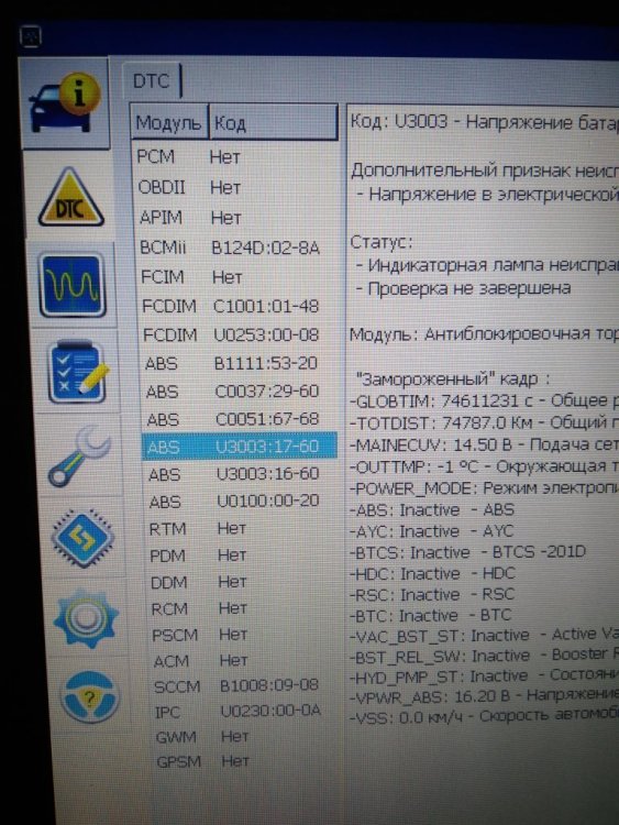
Здравствуйте формучане! Подключил шнурок с помощью forscan и в DTC увидел гирлянду ошибок:
BCM 124D:02-08A — датчик давления шин неисправен
FCDIM C1001:01-48 — камеру заднего вида активировал
FCDIM U0253:00-08 — Утрачена связь с дополнительным модулем интерфейса протокола?
ABS B1111:53-20 — ?
ABS C0037:29-60 -?
ABS C0051:67-68 — проблема с датчиком положения рулевого колеса
ABS U3003:17-60 — напряжение аккумуляторной батареи?
ABS U3003:16-60 — напряжение аккумуляторной батареи?
ABS U0100:00-20 — Потеряна связь с ECM / PCM A?
SCCM B1008:09-08 — переключатель работы стеклоочистителя
IPC U0230:00-0A — потеря связи с модулем багажного отделения
После сброса ошибок, появляются повторно. При этом Check engine, ABS и другие контрольные лампы не горят.
Больше всего интересуют ошибки связанные с АБС. Да и в целом.
Может кто встречался с подобной бедой? Здесь на форуме не нашел.
В общем я понял так:
что надо заново обучить блок TPM наличию датчиков давления.
Для этого надо:
1.Поверните выключатель зажигания в положение off,
2.затем нажмите и отпустите педаль тормоза.
3.Поверните замок зажигания из положение off в положение Run 3 раза, закончив в положении «Run».
4.Нажмите и отпустите педаль тормоза.
5.Поверните выключатель зажигания в положение off.
6.Поверните переключатель зажигания из положение off в положение Run 3 раза, закончив в положении «Run».
Рог будет звучать один раз и индикатор СКДШ будет мигать в случае, если режим тренировки были успешно внесены.
На приборке появится сообщение, о переходе к обучению датчиков.
Примечание: это может занять до 6 секунд, чтобы активировать датчик давления в шинах.
Для активации контроля давления в шинах должен быть инструмент чем нажать на клапан соска в шине.
7.Нажмите и отпустите кнопку теста на приборной панели, для активации контроля давления в шинах.
Рог будет кратко звук, чтобы указать, что датчик давления в шинах была признана ВСМ .
В течение 2 минут звучания клаксона, нажмите на клапан соска на 6 сек.
Примечание: не ждать более 2 минут между обучением каждого датчика, иначе придётся всю процедуру повторить.
Повторите шаг 7 для каждой шины
Процедура будет завершена после обучения последнего датчика и об этом будет сообщение на дисплее.
И вот не совсем понятно с моментом нажатия клапана соска.
Может кто поточнее перенвести этот фрагмент?
:The horn will sound once and the TPMS indicator will flash if the training mode has been entered successfully. If equipped, the message center will display TRAIN LF TIRE.
NOTE: It may take up to 6 seconds to activate a tire pressure sensor. During this time, the Tire Pressure Monitor Activation Tool must remain in place at the valve stem.
Place the Tire Pressure Monitor Activation Tool on the LF tire sidewall at the valve stem. Press and release the test button on the Tire Pressure Monitor Activation Tool. The horn will sound briefly to indicate that the tire pressure sensor has been recognized by the BCM .
Within 2 minutes of the horn sounding, place the Tire Pressure Monitor Activation Tool on the RF tire sidewall at the valve stem and press and release the test button to train the RF tire pressure sensor.
NOTE: Do not wait more than 2 minutes between training each sensor or the BCM will time out and the entire procedure must be repeated.
Repeat Step 7 for the RR and LR tires.
The procedure is completed after the last tire has been trained. When the training procedure is complete, the message center (if equipped) will display TIRE TRAINING COMPLETE.
Изменено 19 мая 2017 пользователем sovg
СИСТЕМА ОСВЕЩЕНИЯ, Diagnostic DTC:B124D, B2432

| Код DTC | Наименование DTC |
|---|---|
| B124D | Прекращение обмена данными с AFS в сети LIN |
| B2432 | Прекращение обмена данными с датчиком системы автоматического включения дальнего света |
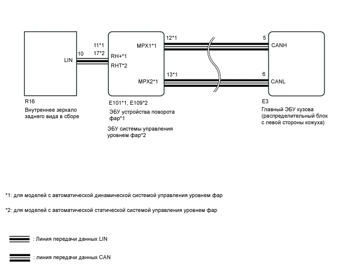
DTC B124D сохраняется, когда главный ЭБУ кузова обнаруживает неисправности в системе передачи данных LIN.
DTC B2432 сохраняется, когда ЭБУ устройства поворота фар обнаруживает неисправности в системе передачи данных LIN.
| Код DTC | Условие обнаружения DTC | Неисправный участок | |||||||||||||||||||||||||
|---|---|---|---|---|---|---|---|---|---|---|---|---|---|---|---|---|---|---|---|---|---|---|---|---|---|---|---|
| B124D | Неисправность в системе передачи данных LIN |
Внутреннее зеркало заднего вида в сборе Жгут или разъем ЭБУ устройства поворота фар*1 ЭБУ системы управления уровнем фар*2 |
|||||||||||||||||||||||||
| B2432 | Неисправность в системе передачи данных LIN |
Внутреннее зеркало заднего вида в сборе Жгут или разъем ЭБУ устройства поворота фар*1 ЭБУ системы управления уровнем фар*2 *1: для моделей с автоматической динамической системой управления уровнем фар *2: для моделей с автоматической статической системой управления уровнем фар СХЕМА ЭЛЕКТРИЧЕСКИХ СОЕДИНЕНИЙ
ПРЕДОСТЕРЕЖЕНИЕ / ПРИМЕЧАНИЕ / УКАЗАНИЕ Прежде чем приступать к диагностике для данного признака неисправности, проверьте работу системы передачи данных в соответствии с указаниями раздела «Порядок поиска неисправностей», чтобы подтвердить работоспособность шины CAN. Сбросьте коды DTC (см. стр. Click here). Проверьте коды DTC (см. стр. Click here).
ВЫПОЛНИТЕ ПРОВЕРКУ С ИМИТАЦИЕЙ УСЛОВИЙ ВОЗНИКНОВЕНИЯ НЕИСПРАВНОСТИ (см. стр. Click here)
ПРОВЕРЬТЕ ЖГУТ ПРОВОДОВ И РАЗЪЕМ (ЭБУ ФАР – ВНУТРЕННЕЕ ЗЕРКАЛО ЗАДНЕГО ВИДА)
Отсоедините разъем E101*1 или E109*2 ЭБУ. *1: для моделей с автоматической динамической системой управления уровнем фар *2: для моделей с автоматической статической системой управления уровнем фар Отсоедините разъем R16 зеркала. Измерьте сопротивление в соответствии со значениями, приведенными в таблице ниже.
для моделей с автоматической динамической системой управления уровнем фар для моделей с автоматической статической системой управления уровнем фар
|
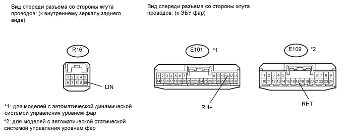
| NG |  |
ОТРЕМОНТИРУЙТЕ ИЛИ ЗАМЕНИТЕ ЖГУТ ПРОВОДОВ ИЛИ РАЗЪЕМ |
| OK |
 |
ПРОВЕРЬТЕ ВНУТРЕННЕЕ ЗЕРКАЛО ЗАДНЕГО ВИДА В СБОРЕ
Временно замените внутреннее зеркало заднего вида новым или заведомо исправным (см. стр. Click here).
Проверьте коды DTC (см. стр. Click here).
| OK |
|---|
| DTC B124D и B2432 не выводятся. |
Результат
| Результат | Перейдите к |
|---|---|
| OK | А |
| NG (для моделей с левосторонним рулевым управлением и автоматической динамической системой управления уровнем фар) | B |
| NG (для моделей с правосторонним рулевым управлением и автоматической динамической системой управления уровнем фар) | C |
| NG (для моделей с левосторонним рулевым управлением и автоматической статической системой управления уровнем фар) | D |
| NG (для моделей с правосторонним рулевым управлением и автоматической статической системой управления уровнем фар) | E |
| А | |
КОНЕЦ (ВНУТРЕННЕЕ ЗЕРКАЛО ЗАДНЕГО ВИДА В СБОРЕ ОКАЗАЛОСЬ НЕИСПРАВНО) |
ЗАМЕНИТЕ ЭБУ УСТРОЙСТВА ПОВОРОТА ФАР (см. стр. Click here)
| B | |
ЗАМЕНИТЕ ЭБУ УСТРОЙСТВА ПОВОРОТА ФАР (см. стр. Click here)
| C | |
ЗАМЕНИТЕ ЭБУ СИСТЕМЫ УПРАВЛЕНИЯ УРОВНЕМ ФАР В СБОРЕ (см. стр. Click here)
| D | |
ЗАМЕНИТЕ ЭБУ СИСТЕМЫ УПРАВЛЕНИЯ УРОВНЕМ ФАР В СБОРЕ (см. стр. Click here)
Источник
СИСТЕМА АВТОМАТИЧЕСКОГО ВКЛЮЧЕНИЯ ДАЛЬНЕГО СВЕТА, Diagnostic DTC:B124D, B2432
| E | |
| Код DTC | Наименование DTC |
|---|---|
| B124D | Прекращение обмена данными с AFS в сети LIN |
| B2432 | Прекращение обмена данными с датчиком системы автоматического включения дальнего света |
ЭБУ системы AFS (ЭБУ устройства поворота фар) получает сигнал включения дальнего света (для системы автоматического включения дальнего света), поступающий от внутреннего зеркала заднего вида (датчика системы автоматического включения дальнего света) и передает его на главный ЭБУ кузова (бортовой ЭБУ сети мультиплексной связи).
| № DTC | Неисправность | Условие обнаружения DTC | Неисправный участок | |||||||||||||||||||||||||
|---|---|---|---|---|---|---|---|---|---|---|---|---|---|---|---|---|---|---|---|---|---|---|---|---|---|---|---|---|
| B124D | Прекращение обмена данными с AFS в сети LIN | Неисправность в канале связи LIN между ЭБУ системы AFS (ЭБУ устройства поворота фар) и внутренним зеркалом заднего вида (датчиком системы автоматического включения дальнего света). |
Внутреннее зеркало заднего вида в сборе (датчик системы автоматического включения дальнего света) Жгут или разъем ЭБУ системы AFS (ЭБУ устройства поворота фар в сборе) |
|||||||||||||||||||||||||
| B2432 | Прекращение обмена данными с датчиком системы автоматического включения дальнего света | Неисправность в канале связи LIN между ЭБУ системы AFS (ЭБУ устройства поворота фар) и внутренним зеркалом заднего вида (датчиком системы автоматического включения дальнего света). |
Внутреннее зеркало заднего вида в сборе (датчик системы автоматического включения дальнего света) Жгут или разъем ЭБУ системы AFS (ЭБУ устройства поворота фар в сборе) СХЕМА ЭЛЕКТРИЧЕСКИХ СОЕДИНЕНИЙ
ПРЕДОСТЕРЕЖЕНИЕ / ПРИМЕЧАНИЕ / УКАЗАНИЕ Прежде чем приступать к следующей процедуре, проверьте работу системы передачи данных согласно указаниям раздела «Система диагностики» и убедитесь, что система передачи данных CAN исправна. Прежде чем приступать к следующим операциям, проверьте состояние внутреннего зеркала заднего вида. В случае замены ЭБУ системы AFS (ЭБУ устройства поворота фар) необходимо выполнить синхронизацию информации об автомобиле и инициализацию ЭБУ системы AFS (ЭБУ устройства поворота фар). Сбросьте коды DTC. Body Electrical > Main Body > Clear DTCsBody Electrical > AFS > Clear DTCs Проверьте наличие кодов DTC. Body Electrical > Main Body > Trouble CodesBody Electrical > AFS > Trouble Codes
ВЫПОЛНИТЕ ПРОВЕРКУ С ИМИТАЦИЕЙ УСЛОВИЙ ВОЗНИКНОВЕНИЯ НЕИСПРАВНОСТИ Нажмите здесь ПРОВЕРЬТЕ ЖГУТ ПРОВОДОВ И РАЗЪЕМ (ЭБУ СИСТЕМЫ AFS (ЭБУ УСТРОЙСТВА ПОВОРОТА ФАР) — ВНУТРЕННЕЕ ЗЕРКАЛО ЗАДНЕГО ВИДА (ДАТЧИК АВТОМАТИЧЕСКОГО ВКЛЮЧЕНИЯ ДАЛЬНЕГО СВЕТА ФАР)). Отсоедините разъем A93 ЭБУ системы AFS (ЭБУ устройства поворота фар в сборе). Отсоедините разъем O3 внутреннего зеркала заднего вида в сборе. Измерьте сопротивление в соответствии со значениями, приведенными в таблице ниже.
ОТРЕМОНТИРУЙТЕ ИЛИ ЗАМЕНИТЕ ЖГУТ ПРОВОДОВ ИЛИ РАЗЪЕМ ПРОВЕРЬТЕ ЭБУ СИСТЕМЫ AFS (ЭБУ УСТРОЙСТВА ПОВОРОТА ФАР В СБОРЕ) Подсоедините разъем A93 ЭБУ системы AFS (ЭБУ устройства поворота фар в сборе). Подсоедините осциллограф к разъему внутреннего зеркала заднего вида в сборе.
Вид спереди разъема со стороны жгута проводов: (к внутреннему зеркалу заднего вида в сборе) Проверьте форму сигнала.
ЗАМЕНИТЕ ВНУТРЕННЕЕ ЗЕРКАЛО ЗАДНЕГО ВИДА В СБОРЕ Нажмите здесь ЗАМЕНИТЕ ЭБУ СИСТЕМЫ AFS (ЭБУ УСТРОЙСТВА ПОВОРОТА ФАР В СБОРЕ) Нажмите здесь Источник ➤ Adblock |


- Печать
Страницы: 1 … 44 45 46 47 48 49 50 [51] 52 53 Вниз

Тема: Датчики давления на Explorer V (Прочитано 226292 раз)
0 Пользователей и 1 Гость просматривают эту тему.
LV,
Все меню облазил — нету ( Американская сборка. Смотрел в руководстве, тоже не нашел. В Display Mode показывает текущее давление (слева спереди прочерк), и как-то сбросить (например, длинным нажатием OK) не выходит.
Подскажите, где в форскане можно прописать ID датчика? Я его сфоткал до установки, если ID указан верный, попробовал бы так прописать.

Записан


Billy,
LV,
В Display Mode показывает текущее давление (слева спереди прочерк)
Уже неплохо. Ошибки системы контроля давления шин нет. По форскану уточню: ID датчиков можно прописать, но, как утверждают гуру, не для Форда. Только IDS. Предыдущий пост поправлю. Однако можно попробовать Форсканом прочитать ID датчиков. Если считывается ID нового датчика, то ещё не 100% вероятность, что он плохой. Такая ситуация может возникнуть, если автоматическая инициализация датчика проводилась на недокачанном колесе. Приблуда или IDS в этом случае не потребуются.
Если новый ID не читается, то искать приблуду или IDS. Причём, для приблуды колесо с новым датчиком желательно не должно быть левым передним, так как с него начинается запись и нужно быть уверенным, процесс записи идет (однократный звуковой сигнал).
Записан
LV, пишет ошибку датчика — Tire Pressure Sensor Fault и горит лампочка спущенного колеса. Облазил форскан, не нахожу ничего касательно TPMS, кроме сервисной процедуры инициализации датчиков. Может помните, где находили инфу по номерам датчиков?
Записан
Подскажите. Через Forscan можно вообще отключить эту систему полностью?
Записан
Да, можно,в расширенной версии с ноутбука
Записан
Всем, привет.
Недавно приобрел Ford Exp 5 первый рестайл (2017 год выпуска). Машина была на зимней резине, приобрел летние колеса с датчиками, перекинул. На приборке появилась ошибка, не видит датчиков. Везде пишут, что нужно запустить процедуру реиницилизации датчиков через левое меню. Так вот облазил все меню, не нашел такой функции, есть режим приборки, где отображаются четыре колеса и давление в кПа (с прочерками), в настройках тоже ничего. Проехал с момента установки колес около 70км. Датчики сами не подцепились.
Что делаю не так ? 
Записан

По мойму просто ОК нажимаешь типа как сброс и идёт процесс инициализации.
Записан
У меня была такая история,также поменял колеса лето на зиму,и на тебе, пишет ошибку с датчиками, не видит их. Сброс не помогал,поехал к О.Д. Поменяли все датчики, результатов ноль.Всю голову сломали, проверяют,датчики рабочие, ставят, не работают. Причина: у меня в багажнике лежал рулон фольгированного утеплителя, хотя болтался он там давно,и проблем не было,убрали утеплитель и все ОК. Вот так.
« Последнее редактирование: 27 Апрель 2020, 13:28:16 от Pavlyxa »
Записан
Записан


Записан
Записан
Тоже приобрёл эту приблуду. Работает, теперь знаю что неисправен задний левый датчик.
Хочу с али заказать, вот только с номерком не ошибиться бы. Машина 2012 года американец.
Записан

Здравствуйте. Машина 2013г. По трассе вылезла ошибка сбой датчика давления в шине. Форскан показал ошибку B124d, вывел показания давления колёс и начал спускать. В итоге показания левого переднего колеса ни как не реагировали. Есть идеи что можно ещё предпринять без снятия колеса??? Спасибо.
Записан
Машина 2012г. (модельный год 2013), по каталогу экзиста датчик BB5Z-1A189-A.
Снял колесо и вынул датчик, а там другой номер BB5T-1A150-AA
Хочу заказать на али, но кому верить не пойму.
Записан


- Печать
Страницы: 1 … 44 45 46 47 48 49 50 [51] 52 53 Вверх
- Клуб владельцев Ford Explorer 5, Ford Explorer Sport и не только….. »
- Общетехнический раздел »
- Колеса и шины »
- Датчики давления на Explorer V
Наши друзья и партнеры
Добрый день!
Постепенно отваливается электрика:
— круиз-контроль: нестабильно, то работает, то нет (проблема уже встречалась пару лет назад, тогда по гарантии устранили, сказали, что проблемы сборки были);
— парктроник: нестабильно, то работает, то длинный сигнал и мигание его кнопки, потом выключается, в основном после мокрой дороги, но и утром после стоянки тоже бывает, началось недавно, с месяц назад;
— в какой-то момент не работала левая противотуманка, была ошибка по ней, потом заработала сама;
— перегорела лампа подсветки угла при повороте в левой фаре, заменил сам;
— и наконец (на следующий день полсле замены угловой лампы), «Неисправны передние фары» — это обрадовало меня вечером перед дальней поездкой, что не так — сразу не понял, свет был и есть, только в пути понял, что светят фары вниз. Ошибка C1A05:14-2F — Левый задний датчик высоты.
Притом к концу поездки ошибка пропала, фары встали нормально (было неделю назад). Но на следующий день опять неисправны и больше сами не «чинились».
Запускал тест блока HCM — фары ходят вниз и вверх, т.е. с моторчиками все нормально похоже.
По парктронику ошибок нет, есть ошибка по подсветке номера, но она работает, правда я туда воткнул диодные лампочки, штатные перегорали пару раз, но это было очень давно, года 3-4 назад.
Похоже, что все это впервые начиналось после мойки (кроме круиза) на следующий день, но это не точно.
Подскажите, может был подобный или частично похожий опыт, это отвалилось несколько блоков/датчиков или где-то, где может быть все эти линии пересекаются просто сгнила проводка?
Понимаю, что конечно же нужна диагностика, посему второй вопрос: порекомендуйте пожалуйста толкового электрика/электронщика по форду в Питере. Не хочется зря менять рабочие блоки, если проблемы в проводке)
Ниже коды ошибок.
===PCM DTC U0405:00-68===
Код: U0405 — Недействительные данные, полученные от модуля управления системой круиз-контроля
Статус:
— Предварительно генерированный DTC, отсутствующий на момент запроса
— Индикаторная лампа неисправности выключена для этого DTC
— Проверка не завершена
===HCM DTC C1A05:14-2F===
Код: C1A05 — Левый задний датчик высоты
Дополнительный признак неисправности:
— Короткое замыкание на массу или разрыв электрической цепи
Статус:
— DTC присутствует в момент запроса
— Индикаторная лампа неисправности выключена для этого DTC
Модуль: Модуль управления фарами
===END HCM DTC C1A05:14-2F===
===BCMii DTC C1D22:49-28===
Код: C1D22 — Правый блок переключателей на рулевом колесе
Дополнительный признак неисправности:
— Внутренняя электронная неисправность
Статус:
— Предварительно генерированный DTC, отсутствующий на момент запроса
— Индикаторная лампа неисправности выключена для этого DTC
Модуль: Модуль управления кузовом
«Замороженный» кадр :
-GLOBTIM: 3010257 сек — Общее реальное время
-TOTDIST: 93575.0 Км — Общий путь
-MAINECUV: 14.50 Вольт — Подача сетевого напряжения к ECU
-INCARTMP: 24 °C — Температура в салоне
===END BCMii DTC C1D22:49-28===
===BCMii DTC C2003:49-28===
Код: C2003 — Левый блок переключателей на рулевом колесе
Дополнительный признак неисправности:
— Внутренняя электронная неисправность
Статус:
— Предварительно генерированный DTC, отсутствующий на момент запроса
— Индикаторная лампа неисправности выключена для этого DTC
Модуль: Модуль управления кузовом
«Замороженный» кадр :
-GLOBTIM: 2988279 сек — Общее реальное время
-TOTDIST: 91086.0 Км — Общий путь
-MAINECUV: 14.50 Вольт — Подача сетевого напряжения к ECU
-INCARTMP: 22 °C — Температура в салоне
===END BCMii DTC C2003:49-28===
===BCMii DTC B109B:15-2F===
Код: B109B — Фонарь освещения номерного знака
Дополнительный признак неисправности:
— Короткое замыкание на + аккумулятора или разрыв электрической цепи
Статус:
— DTC присутствует в момент запроса
— Индикаторная лампа неисправности выключена для этого DTC
Модуль: Модуль управления кузовом
«Замороженный» кадр :
-GLOBTIM: 2967949 сек — Общее реальное время
-TOTDIST: 89708.0 Км — Общий путь
-MAINECUV: 11.50 Вольт — Подача сетевого напряжения к ECU
-INCARTMP: 23 °C — Температура в салоне
===END BCMii DTC B109B:15-2F===
===BCMii DTC B1147:15-68===
Код: B1147 — Левые передние противотуманные фонари
Дополнительный признак неисправности:
— Короткое замыкание на + аккумулятора или разрыв электрической цепи
Статус:
— Предварительно генерированный DTC, отсутствующий на момент запроса
— Индикаторная лампа неисправности выключена для этого DTC
— Проверка не завершена
Модуль: Модуль управления кузовом
«Замороженный» кадр :
-GLOBTIM: 2968220 сек — Общее реальное время
-TOTDIST: 89805.0 Км — Общий путь
-MAINECUV: 14.50 Вольт — Подача сетевого напряжения к ECU
-INCARTMP: 27 °C — Температура в салоне
===END BCMii DTC B1147:15-68===
Спасибо за внимание, всем добра!
Здравствуйте формучане! Подключил шнурок с помощью forscan и в DTC увидел гирлянду ошибок:
BCM 124D:02-08A — датчик давления шин неисправен
FCDIM C1001:01-48 — камеру заднего вида активировал
FCDIM U0253:00-08 — Утрачена связь с дополнительным модулем интерфейса протокола?
ABS B1111:53-20 — ?
ABS C0037:29-60 -?
ABS C0051:67-68 — проблема с датчиком положения рулевого колеса
ABS U3003:17-60 — напряжение аккумуляторной батареи?
ABS U3003:16-60 — напряжение аккумуляторной батареи?
ABS U0100:00-20 — Потеряна связь с ECM / PCM A?
SCCM B1008:09-08 — переключатель работы стеклоочистителя
IPC U0230:00-0A — потеря связи с модулем багажного отделения
После сброса ошибок, появляются повторно. При этом Check engine, ABS и другие контрольные лампы не горят.
Больше всего интересуют ошибки связанные с АБС. Да и в целом.
Может кто встречался с подобной бедой? Здесь на форуме не нашел.
Причины возникновения ошибки B124D на FORD
Найдено значений ошибки: 2
Датчик давления в шине
Контроллер давления в шинах неисправен или передает неверные показания на блок управления. Надо проверить контакты датчика
Если при диагностике обнаружено несколько ошибок, то их следует устранять в порядке обнаружения сканером. После устранения причины воникновения ошибки произведите их чистку и выполните тест-драйв автомобиля.