
JCB диагностические коды неисправностей — блинк коды
JCB диагностические коды неисправности -блинк коды
JCB (Джисиби) FAULT CODES на русском языке
P0087 (код мигания 227) давление в топливной рампе слишком низкое (для насоса без подачи давления)
• Сильная вибрация двигателя.
• Нестабильный холостой ход
• Выходное падение мощности
• Может быть слишком большой выход дыма
P0088 (мигающий код 118) давление в топливной рампе слишком высокое
• Сильная вибрация двигателя
• холостой ход нестабильный
• Выходное падение мощности
• отказ в откачке газового двигателя
• Может быть слишком большой выход
P0089 (мигающий код 151) регулятор давления в топливной рампе неисправен
• Сильная вибрация двигателя
• холостой ход нестабильный
• Выходное падение мощности
• Может быть слишком большой выход
P0090 (мигающий код 247) SCV обрыв или закорочен регулятор давления топлива
• В зависимости от открытых / коротких ситуаций может быть остановка двигателя и / или запуск
P0107 (мигающий код 71) Входной сигнал датчика атмосферного давления низкий (открыт или закорочен на массу)
Из-за запасной эквивалентной высоты 2000 м (6562 фута)
• выхлопной дым на большой высоте.
• недостаточная мощность на малой высоте
P0108 (мигающий код 71) Входной сигнал датчика атмосферного давления высокий (+ 5 В закорочен)
Из-за запасной эквивалентной высоты 2000 м (6562 фута)
• отсутствие мощности на малой высоте
P0112 (код мигания 22) неисправность датчика температуры всасываемого воздуха (ошибка низкого напряжения, замыкание на землю, короткое замыкание)
• При холодном запуске может выделяться белый дым.
P0113 (код мигания 22) неисправность датчика температуры всасываемого воздуха (неисправность цепи высокого напряжения питания)
• При холодном запуске может выделяться белый дым.
P0117 (код мигания 23) неисправность датчика температуры охлаждающей жидкости двигателя (ошибка низкого напряжения, замыкание на землю, короткое замыкание)
• При нормальной температуре: может выделяться дым,
• При низкой температуре окружающей среды на холостом ходу: может быть нестабильный холостой ход,затруднен запуск двигателя
P0118 (код мигания 23) Датчик температуры охлаждающей жидкости двигателя выдает завышенные данные (замкнут на плюс или короткого замыкания)
• При нормальной температуре: может выделяться дым,
• При низких температурах воздуха во время простоя: может быть нестабильный холостой ход,
P0182 (код мигания 211) Неисправность датчика температуры топлива (неисправности низкого напряжения, закороченные на землю)
Воздействие на работоспособность.
P0183 (код мигания 211) Неисправность датчика температуры топлива (сбой высокого напряжения, цепь питания разомкнута или
P0192 (мигающий код 245) датчик давления топлива (низкое напряжение или короткое замыкание)
• Возможно, остановка двигателя
• снижение выходной мощности
P0193 (код ошибки 245) высокий сигнал датчика давления топлива (обрыв или замыкание на плюс)
• двигатель может останавливаться
• Выходное падение мощности
P0201 (мигающий код 271) обрыв цепи управления форсункой 1 цилиндра
• сильная вибрация двигателя
• Нестабильный холостой ход
• Выходная мощность понижена
P0202 (мигающий код 272) обрыв цепи управления форсункой 2 цилиндра
• сильная вибрация двигателя
• Нестабильный холостой ход
• Выходная мощность понижена
P0203 (мигающий код 273) обрыв цепи управления форсункой 3 цилиндра
• сильная вибрация двигателя
• Нестабильный холостой ход
• отказ в откачке газового двигателя
P0204 (мигающий код 274) обрыв цепи управления форсункой 4 цилиндра
• сильная вибрация двигателя
• Нестабильный холостой ход
• Выходная мощность понижена
P0205 (мигающий код 275) обрыв цепи управления форсункой 5 цилиндра
• сильная вибрация двигателя
• Нестабильный холостой ход
• Выходная мощность понижена
P0206 (мигающий код 276) обрыв цепи управления форсункой 6 цилиндра
• сильная вибрация двигателя
• Нестабильный холостой ход
• Выходная мощность занижена
P0219 (мигающий код 543) превышение частоты вращения двигателя
Выходное падение мощности
P0237 (мигающий код 32) сбой датчика давления наддува (ошибка низкого напряжения, разомкнутая цепь)
P0238 (мигающий код 32) отказ датчика давления наддува (сбой высокого напряжения, короткое замыкание на минус)
P0335 (мигающий код 15) неисправность датчика коленчатого вала (без сигнала)
• Выходное падение занижено
• Вибрация двигателя может быть серьезной
• двигатель может остановиться
P0336 (код мигания 15) неисправность датчика коленчатого вала (отказ сигнала)
• Вибрация двигателя может быть серьезной
• двигатель может остановиться (когда датчик положения распределительного вала нормализуется, может завестись с повторным запуском.
Компания Гидро-Максмум выполняет ремонт гидравлической части погрузчиков и другой спецтехники. Возможен выезд специалиста для диагностики на территории клиента.
Источник
JCB 214. Загорелась лампочка! Что за неисправность?
#1 ГонЩик77


Ребята, помогите, такая штуковина. пришел экскаватор из США JCB 214, мануалов нечего нет, когда перегоняли на место стоянки все работало в штатном режиме, на стоянке тоже приходили, заводили, проверяли все хорошо! Сегодня утром заводим, загорелась лампочка, выглядит как давление масла в двигателе, только вокруг как шестеренка со стрелочками и сопровождается звуковым сигналом! Раньше она загоралась при запуске и сразу тухла, а теперь нет! Что за индикатор, о чем он предупреждает.

#2 Chuck

Означает это низкое давления трансмиссионного масла
#3 ГонЩик77
Chuck, спасибо. вот уровень на месте, какая тогда может быть причина?
#4 Chuck
ГонЩик77, я бы копать начал с ревизии фильтра и насоса. Смотря где фильтр стоит и системе, если он отработал своё, то давление или упадет или поднимется выше нормы. На ЭБП-9, знаю, что при забитости фильтра, давление повышается в системе.
#5 Эрл

поменяйте масло,замените фильтр,промойте сеточный фильтр
#6 Эрл
Даже лучше так: замените масло и и фильтра,замерьте давление в КПП,проверяйте на всех скоростях,должно меняться согласно скорости мин.10 макс.14бар,если все в норме,смотрите главный жгут проводки,он идет от соленойдов коробки,датчика давления и вдоль несущей рамы,потрясите разъемы,потяните проводку,может где то коротит. а то как так работал нормально. и бац. загорелась
#7 ГонЩик77
#8 Эрл
ГонЩик77, при сильном охлаждении на моём так-же бывает, (оставлял трактор на улице) заведёшь лампа потухнет, через несколько секунд загорается и горит, но всё работает, едет вперёд и назад. Теперь если холодно, перед заводкой ставлю дизельную пушку (можно паяльную лампу) и подогреваю КПП, масло наливаю 10W. Трактор стоит в неотапливаемом гараже, при сильных холодах температура отпускается до минус 20. После промывки сетки в КПП, стала загораться лампа при более низкой температуре (при минус 15-17 градусов).
Я так понимаю, насос выхватывает масло и захватывает воздух, либо давление слишком большое (предохранительный клапан не справляется).
Масло САТ SAE10 пойдёт в конце должно быть W.
Скорее всего масло густое, если масло не идёт через фильтр, то оно идёт мимо фильтра (через пр.клапан). Масло SAE30 на зиму НЕ пойдёт.
Наливайте 10W и зимой и летом. Я на 10W круглый год.
#9 pasha

Shell Donax TC
SAE 10W 36.0/6.0-вязкость при 40/100 градусов, -36 т.замерзания
SAE 30 93.9/10.9-вязкость при 40/100 градусов, -30 т.замерзания
SAE 50 217.4/19.5-вязкость при 40/100 градусов , -18 т.замерзания
Высококачественное минеральное масло для трансмиссий внедорожной техники. Удовлетворяет жестким требованиям современных трансмиссий с силовым переключением, главных передач, гидравлических тормозов и гидросистем работающей в тяжелых эксплуатационных условиях горной и строительной техники.
Спецификации/допуски: Caterpillar TO-4, GM Allison C-4 (10W, 30), Komatsu KES 07.868-1, ZF TE-ML 03C (10W, 30).
TOTAL DYNATRANS AC — масло для гидравлических систем, силовых трансмиссий, мостов и редукторов конечных передач, для которых производитель рекомендует масло отвечающее требованиям спецификации CATERPILLAR TO -4.
TOTAL DYNATRANS AC применяется для техники CATERPILLAR :
• SAE 10 W для гидравлических систем это наливаю в КПП.
• SAE 30 для силовых трансмиссий
• SAE 50 для редукторов конечных передач
Применяется в силовых и механических трансмиссиях:
• KOMATSU • ZF • EATON FULLER • ALLISON • DANA • ROCKWELL
Спецификации • CATERPILLAR TO-4 • KOMATSU MICRO CLUTCH • ALLISON C4
Типичные характеристики
Ед. изм.
10 W
30
50
Плотность при 15 ?С
кг / м 3
0,881
0,899
0,907
Кинематическая вязкость при 40 ?С
мм 2 /с (сСт)
37
105
225
Кинематическая вязкость при 100 ?С
мм 2 /с (сСт)
6
11,7
19,3
Индекс вязкости
—
106
99
97
Температура застывания
?C
— 30
— 24
— 12
Вот это тоже хорошее масло, я перешел на ТОТАЛ)
Источник
Коды ошибок генераторов jcb
Внимание! Администрация форума (включая модераторов) не продает тех.документацию, запчасти или технику. Если пользователь форума предлагаем вам какой-либо товар от лица администрации форума, то он — мошенник. Не перечисляйте ему деньги!
Нет с этим всё впорядке, излазил его вдоль и поперёк, ничего не нашёл
Так же нашёл недавно инфу что это бусферный насос, кто знает гне он находится?
Клапан разгрузки который под соленоидом черепахи? Вниз вытаскивается кажется?
BST open — цепь питания реле соленоида включения 3го насоса оборвана.
Идите по шлангам от этого насоса, упрётесь в соленоид.
И определитесь — сила пропадает или скорость. Это понятие очень часто путают.
По бст в принципе тоже думаю надо искать клапан на напорном рукаве с третьего насоса, завтра выходной, поищу.
Он как понимаю срабатывает в определенном диапазоне оборотов?
Давление на МРВ при какой температуре выставляется?
Сегодня подцепил мономет, он вообще шкалить начал и визжать, убавил до 250, не понимаю откуда оно берется.
МРВ разобрал, ничего криминального не увидел, Разгрузочный что сверху тоже нормальный. Единственное снизу заглушку под ним не смог выкрутить. Или клапан можно вверх вытащить?
Снизу и сверху стоят два одинаковых больших соленоида, снизу это плавающий, сверху это соленоид подключения третьего насоса? Соленоид черепахи сбоку.
Вообще по трехнасосным машинам есть мануал по гидравлике?
Источник
Коды ошибок генераторов jcb
Внимание! Администрация форума (включая модераторов) не продает тех.документацию, запчасти или технику. Если пользователь форума предлагаем вам какой-либо товар от лица администрации форума, то он — мошенник. Не перечисляйте ему деньги!
мы себе взяли у них 3сх и как раз 160ый колесник.
Тьфу-тьфу, все отлично работает. Там движок как на хитачи, Изуцу стоит.
единственно- у них нет в базе разводки под гидромолот
мы себе взяли у них 3сх и как раз 160ый колесник.
Тьфу-тьфу, все отлично работает. Там движок как на хитачи, Изуцу стоит.
единственно- у них нет в базе разводки под гидромолот
Ну так и есть, это миф о маленьком расходе))Итак
Doosan Solar 180 W-V
Двигатель
Модель . . . . . . . . . . . . . . . . . . . Doosan DB58TIS
Рабочие характеристики
Мощность на маховике . . . 152 (112) л.с. (кВт)
Номинальная частота вращения . . 2100 об/мин
Тип . . . . . . дизельный, 4-х тактный, с водяным
охлаждением и турбонаддувом, рядный, с
непосредственным впрыском
Количество цилиндров . . . . . . . . . . . . . . . . . . . 6
Диаметр цилиндра / ход поршня . . . 102/118мм
Суммарный рабочий объем двигателя . 5,785 л.
Макс. крутящий момент . . . . . . . . . . . . 588 Н*м
Hyundai R170W-7A
Двигатель, л.с. Mitsubishi S6S-DT (ЯПОНИЯ), 126 л.с.
Объем двигателя, см3 4 996
Шестицилиндровый рядный дизельный с жидкост-
ным охлаждением с непосредственным впрыском
и турбонаддувом с воздушным охлаждением
наддувочного воздуха
Ну и каким макаром у Дусана экономичнее?
сейчас сравниваю характеристики по брошюрам, пока явных отличий одной модели от другой не нашел.
взято: http://www.excavator-sdm.ru/ekskavat. solar_180_lcv/
и
http://thgr.ru/
обещаю, как только соберу побольше инфы — открою новую тему
вот в этой теме Дусан обсуждали еще http://exkavator.ru/other/board/show. F1%E0%ED%FB%F7
Ну так и есть, это миф о маленьком расходе))Итак
Doosan Solar 180 W-V
Двигатель
Модель . . . . . . . . . . . . . . . . . . . Doosan DB58TIS
Рабочие характеристики
Мощность на маховике . . . 152 (112) л.с. (кВт)
Номинальная частота вращения . . 2100 об/мин
Тип . . . . . . дизельный, 4-х тактный, с водяным
охлаждением и турбонаддувом, рядный, с
непосредственным впрыском
Количество цилиндров . . . . . . . . . . . . . . . . . . . 6
Диаметр цилиндра / ход поршня . . . 102/118мм
Суммарный рабочий объем двигателя . 5,785 л.
Макс. крутящий момент . . . . . . . . . . . . 588 Н*м
Hyundai R170W-7A
Двигатель, л.с. Mitsubishi S6S-DT (ЯПОНИЯ), 126 л.с.
Объем двигателя, см3 4 996
Шестицилиндровый рядный дизельный с жидкост-
ным охлаждением с непосредственным впрыском
и турбонаддувом с воздушным охлаждением
наддувочного воздуха
Ну и каким макаром у Дусана экономичнее?
сейчас сравниваю характеристики по брошюрам, пока явных отличий одной модели от другой не нашел.
взято: http://www.excavator-sdm.ru/ekskavat. solar_180_lcv/
и
http://thgr.ru/
обещаю, как только соберу побольше инфы — открою новую тему
вот в этой теме Дусан обсуждали еще http://exkavator.ru/other/board/show. F1%E0%ED%FB%F7
Источник
JCB Diagnostic Trouble Codes
JCB Product Support Laptop Based Diagnostic Tool Manual Download
JCB v8+ Electrical Error Fault codes v1-07 Download
Troubleshooting/fault code,error kode JCB Excavator JS 200 JS 210 JS 220 JS 240 JS 260 Download
Flashing codes are described.
P0087 (flashing code 227) fuel rail pressure too low (for a pump without pressure applied)
Main symptoms
• Strong engine vibration.
• Unstable idling
• Output power drop
Exhaust smoke
• There may be too much smoke.
P0088 (flashing code 118) fuel rail pressure too high
Main symptoms
• Strong engine vibration
• idle unstable
• Output power drop
• failure to pump the gas engine
Exhaust smoke
• May be too big a way out.
P0089 (flashing code 151) fuel rail pressure regulator faulty
Main symptoms
• Strong engine vibration
• idle unstable
• Output power drop
Exhaust smoke
• May be too big a way out.
P0090 (flashing code 247) SCV open or short of fuel pressure regulator
Main symptoms
• Depending on the open / short situations, the engine may stop and / or start
Exhaust smoke
• Smoke output too large
P0107 (flashing code 71) Atmospheric pressure sensor input signal low (open or shorted to ground)
Main symptoms
Due to a spare equivalent height of 2000 m (6562 ft)
• exhaust smoke at high altitude.
• insufficient power at low altitude
P0108 (flashing code 71) Atmospheric pressure sensor input high (+ 5 V short-circuited)
Main symptoms
Due to a spare equivalent height of 2000 m (6562 ft)
• High exhaust smoke
• lack of power at low altitude
P0112 (flash code 22) intake air temperature sensor malfunction (low voltage error, ground fault, short circuit)
Main symptoms
• Cold start may emit white smoke.
P0113 (flash code 22) intake air temperature sensor malfunction (high supply voltage circuit fault)
Main symptoms
• Cold start may emit white smoke.
P0117 (flashing code 23) engine coolant temperature sensor malfunction (low voltage error, ground fault, short circuit)
Main symptoms
• At normal temperature: smoke may be emitted,
• When the ambient temperature is low when idling: unstable idling may occur, engine start is difficult
P0118 (flashing code 23) The engine coolant temperature sensor provides overestimated data (closed to positive or short circuit)
Main symptoms
• At normal temperature: smoke may be emitted,
• At low temperatures while idle: there may be an unstable idle,
P0182 (flashing code 211) Malfunctioning fuel temperature sensor (low voltage faults shorted to ground)
Main symptoms
Impact on performance.
P0183 (flashing code 211) Malfunctioning fuel temperature sensor (high voltage failure, power supply circuit open or
short circuit)
P0192 (flashing code 245) fuel pressure sensor (low voltage or short circuit)
Main symptoms
• Perhaps stopping the engine
• reduced output power
P0193 (error code 245) high signal of the fuel pressure sensor (open circuit or short to positive)
Main symptoms
• engine can stop
• Output power drop
P0201 (flashing code 271) open circuit of the injector 1-cylinder control circuit
Main symptoms
• strong engine vibration
• Unstable idling
• Output power lowered.
P0202 (flashing code 272) open circuit of the injector 2 cylinder control
Main symptoms
• strong engine vibration
• Unstable idling
• Output power lowered.
• engine failure
P0203 (flashing code 273) interruption of the injector control circuit 3 cylinders
Main symptoms
• strong engine vibration
• Unstable idling
• Output power
• failure to pump the gas engine
P0204 (flashing code 274) open circuit of the nozzle control circuit 4 cylinder
Main symptoms
• strong engine vibration
• Unstable idling
• Output power lowered.
• engine failure
P0205 (flashing code 275) open injector 5 control circuit
Main symptoms
• strong engine vibration
• Unstable idling
• Output power lowered.
• Engine failure
P0206 (flashing code 276) open circuit of the injector 6 cylinder control circuit
Main symptoms
• strong engine vibration
• Unstable idling
• Output power underestimated
• Engine failure
P0219 (flashing code 543) engine overspeed
Main symptoms
Output power drop
P0237 (flashing code 32) failure of the boost pressure sensor (low voltage error, open circuit)
Main symptoms
smoke
P0238 (flashing code 32) failure of the boost pressure sensor (high voltage failure, short to negative)
P0335 (flashing code 15) crankshaft sensor malfunction (no signal)
Main symptoms
• Output drop underestimated
• exhaust white smoke
• Motor vibration can be severe.
• engine may stop
P0336 (blink code 15) crankshaft sensor malfunction (signal failure)
Main symptoms
• Output drop low
• exhaust white smoke
• Motor vibration can be severe.
• The engine may stop (when the camshaft position sensor is normalized, it may start up again.
Error Codes/ Error String/ Description
101 CRANK A crank signal was not detected by the ECU1.
102 FUEL The fuel sensor is open-circuit
103 EN TMP The engine temperature sensor is open-circuited.
104 HYD TMP The hydraulic temperature sensor is open-circuited.
105 SET PT The throttle set potentiometer is open-circuited.
106 SENS PT The throttle sense potentiometer is open-circuited.
107 OIL SW The oil pressure switch is reporting oil pressure is present when the engine is not running.
108 FLYWHEEL The flywheel sensor is reporting an engine speed even though the engine is not running.
109 ALT The alternator is reporting a voltage even when the engine is not running.
110 THR SOL The throttle solenoid is open-circuited. This can only be detected when the engine is not running.
111 BOOM SP The boom lower speed regulation output is open-circuited.
113 MAX FLW The max flow solenoid is open-circuited. For JS200W machines, this error can only be detected when the
engine is not running due to the fact that this is a proportional valve on these machines.
115 BOOM The boom priority solenoid is open-circuited.
116 FL PMP The refuel pump output is open-circuited.
117 HORN The horn output is open-circuited.
118 HYD PMP The hydraulic pump is open-circuited. Because this is a proportional valve, this error can only be detected
when the engine is not running.
119 SLW LCK The slew lock solenoid is open-circuited.
120 HYD FAN The hydraulic fan output is open-circuited. This can only be detected when the engine is not running.
121 SLW BRK The slew brake solenoid is open-circuited.
122 SLW ST The slew shut off solenoid is open-circuited.
127 TL CHNG The travel change solenoid is open-circuited.
128 WASHER The washer motor is open-circuited.
129 DOZER The dozer solenoid is open-circuited.
130 GRB CW The grab/rotate clockwise solenoid is open-circuited.
131 GRB CCW The grab/rotate counter-clockwise solenoid is open-circuited.
132 LW FLOW The low flow solenoid is open-circuited.
133 ISOL The hydraulic isolator solenoid is open-circuited.
135 2 STAGE The 2nd stage relief solenoid is open-circuited.
136 QK HTCH The quick hitch solenoid is open-circuited.
138 HAMMER The hammer solenoid is open-circuited.
139 CUSHION The hard/soft cushion solenoid is open-circuited.
142 ENG SD The engine shutdown output is open-circuited.
143 GLW PLG The glow plugs output is open-circuited.
156 TL FLW3 The travel flow 3 solenoid is open-circuited.
157 TL FLW2 The travel flow 2 solenoid is open-circuited.
158 GR CHNG The M2 or gear change solenoid is open-circuited.
159 BRKE LT The brake light output is open-circuited.
160 AXLE LK The axle lock solenoid is open-circuited.
161 STAB UP The stabilizer up (Rear Right on Auto’s) solenoid is open-circuited.
162 STAB DN The stabilizer down (Front Left / Front Dozer on Auto’s) solenoid is open-circuited.
163 STAB LH The stabilizer left (Rear Left / Rear Dozer on Auto’s) solenoid is open-circuited.
164 STAB RH The stabilizer right (Front Right on Auto’s) solenoid is open-circuited.
165 CRUISE The cruise control solenoid is open-circuited.
166 DIG ISL The dig end isolation solenoid is open-circuited.
167 PRK BK The M1 or park brake solenoid is open-circuited.
168 DRV ISL The drive isolate solenoid is open-circuited.
202 FUEL The fuel level sensor is short-circuited.
203 EN TMP The engine temperature sensor is short-circuited.
204 HYD TMP The hydraulic temperature sensor is short-circuited.
205 SET PT The throttle set potentiometer is short-circuited.
206 SENS PT The throttle sense potentiometer is short-circuited.
210 THR SOL The throttle solenoid is short-circuited. This can only be detected when the engine is not running.
211 BOOM SP The boom lower speed regulation output is short-circuited.
212 INT LT The interior light is short-circuited.
213 MAX FLW The max flow solenoid is short-circuited. For JS200W machines, this error can only be detected when the
engine is not running due to the fact that this is a proportional valve on these machines.
214 BEACON The beacon output is short-circuited.
215 BOOM PR The boom priority solenoid is short-circuited.
216 FL PMP The refuel pump solenoid is short-circuited.
217 HORN The horn output is short-circuited.
218 HYD PMP The hydraulic pump is short-circuited. Because this is a proportional valve, this error can only be detected
when the engine is not running.
219 SLW LCK The slew lock solenoid is short-circuited.
220 HYD FAN The hydraulic fan solenoid is short-circuited. The fault can only be detected when the engine is not running.
221 SLW BRK The slew brake solenoid is short-circuited.
222 SLW ST The slew shut off solenoid is short-circuited.
223 LW WIPR The lower wiper motor is short-circuited.
224 WIPER The wiper motor is short-circuited.
225 LH CAB LT The boom work light is short-circuited.
226 RH CAB LT The toolbox work light is short-circuited.
227 TL CHNG The travel change solenoid is short-circuited.
228 WASHER The washer motor is short-circuited.
229 DOZER The dozer solenoid is short-circuited.
230 GRB CW The grab/rotate clockwise solenoid is short-circuited.
231 GRB CCW The grab/rotate counter-clockwise solenoid is short-circuited.
232 LW FLOW The low flow solenoid is short-circuited.
233 ISOL The isolator solenoid is short-circuited.
234 EMG STP The emergency stop solenoid is short-circuited.
235 2 STAGE The 2nd stage relief solenoid is short-circuited.
236 QK HTCH The quick hitch solenoid is short-circuited.
237 TL ALRM The travel alarm output is short-circuited.
238 HAMMER The hammer solenoid is short-circuited.
239 CUSHION The hard/soft cushion solenoid is short-circuited.
240 BOOM LT The boom work light is short-circuited.
241 TLBX LT The toolbox work light is short-circuited.
242 ENG SD The engine shutdown solenoid is short-circuited.
243 GLW PLG The glow plugs are short-circuited.
244 CNT LT The counter-weight work light is short-circuited.
245 LH IND The LH turn indicator is short-circuited.
246 LH SIDE The LH sidelight is short-circuited.
247 LH FOG The LH fog light is short-circuited.
248 LH MAIN The LH main beam is short-circuited.
249 LH DIP The LH dip beam is short-circuited.
250 RH IND The RH turn indicator is short-circuited.
251 RH SIDE The RH sidelight is short-circuited.
252 RH FOG The RH fog light is short-circuited
253 RH MAIN The RH main beam is short-circuited.
254 RH DIP The RH dip beam is short-circuited.
255 HZD LED The hazard LED is short-circuited.
256 TL FLW3 The travel flow 3 solenoid is short-circuited.
257 TL FLW2 The travel flow 2 solenoid is short-circuited.
258 GR CHNG The M2 or gear change solenoid is short-circuited.
259 BRKE LT The brake light output is short-circuited.
260 AXLE LK The axle lock solenoid is short-circuited.
261 STAB UP The stabilizer up solenoid is short-circuited.
262 STAB DN The stabilizer down solenoid is short-circuited.
263 STAB LH The stabilizer left solenoid is short-circuited.
264 STAB RH The stabilizer right solenoid is short-circuited.
265 CRUISE The cruise control solenoid is short-circuited.
266 DIG ISL The dig end isolate solenoid is short-circuited.
267 PRK BK The M1 or park brake solenoid is short-circuited.
268 DRV ISL The drive isolate solenoid is short-circuited.
300 EC1 CAN The ECU1 module is no longer communicating on the CAN bus.
301 ECW CAN The ECUW module is no longer communicating on the CAN bus.
302 THRT CAL The difference between the minimum and maximum calibration points for the throttle dial pot is less than 100
A/D points.
303 THRT CAL The difference between the minimum and maximum calibration points for the throttle sense pot is less than
100 A/D points. This error does not exist on machines fitted with an EEC.
304 THRT CAL The throttle dial pot is greater than 10% but the engine is still running at the idle position. This condition must
exist for at least 15 seconds before it is reported. This error does not exist on machines fitted with an EEC.
305 THRT CAL The error term of the PID algorithm is greater than 20 A/D points for more than 20 consecutive seconds.
Home » JCB » JCB JS-Excavator’s Fault Codes List
See also:
- JCB Service Repair Manuals PDF
- JCB flash codes list
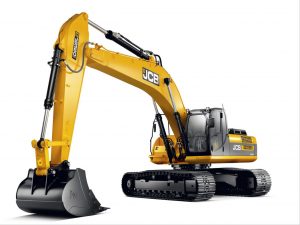
JCB JS330
| Error Codes | Error String | Description |
| 101 | CRANK | A crank signal was not detected by the ECU1. |
| 102 | FUEL | The fuel sensor is open-circuit |
| 103 | EN TMP | The engine temperature sensor is open-circuited. |
| 104 | HYD TMP | The hydraulic temperature sensor is open-circuited. |
| 105 | SET PT | The throttle set potentiometer is open-circuited. |
| 106 | SENS PT | The throttle sense potentiometer is open-circuited. |
| 107 | OIL SW | The oil pressure switch is reporting oil pressure is present when the engine is not running. |
| 108 | FLYWHEEL | The flywheel sensor is reporting an engine speed even though the engine is not running. |
| 109 | ALT | The alternator is reporting a voltage even when the engine is not running. |
| 110 | THR SOL | The throttle solenoid is open-circuited. This can only be detected when the engine is not running. |
| 111 | BOOM SP | The boom lower speed regulation output is open-circuited. |
| 113 | MAX FLW | The max flow solenoid is open-circuited. For JS200W machines, this error can only be detected when the
engine is not running due to the fact that this is a proportional valve on these machines. |
| 115 | BOOM | The boom priority solenoid is open-circuited. |
| 116 | FL PMP | The refuel pump output is open-circuited. |
| 117 | HORN | The horn output is open-circuited. |
| 118 | HYD PMP | The hydraulic pump is open-circuited. Because this is a proportional valve, this error can only be detected
when the engine is not running. |
| 119 | SLW LCK | The slew lock solenoid is open-circuited. |
| 120 | HYD FAN | The hydraulic fan output is open-circuited. This can only be detected when the engine is not running. |
| 121 | SLW BRK | The slew brake solenoid is open-circuited. |
| 122 | SLW ST | The slew shut off solenoid is open-circuited. |
| 127 | TL CHNG | The travel change solenoid is open-circuited. |
| 128 | WASHER | The washer motor is open-circuited. |
| 129 | DOZER | The dozer solenoid is open-circuited. |
| 130 | GRB CW | The grab/rotate clockwise solenoid is open-circuited. |
| 131 | GRB CCW | The grab/rotate counter-clockwise solenoid is open-circuited. |
| 132 | LW FLOW | The low flow solenoid is open-circuited. |
| 133 | ISOL | The hydraulic isolator solenoid is open-circuited. |
| 135 | 2 STAGE | The 2nd stage relief solenoid is open-circuited. |
| 136 | QK HTCH | The quick hitch solenoid is open-circuited. |
| 138 | HAMMER | The hammer solenoid is open-circuited. |
| 139 | CUSHION | The hard/soft cushion solenoid is open-circuited. |
| 142 | ENG SD | The engine shutdown output is open-circuited. |
| 143 | GLW PLG | The glow plugs output is open-circuited. |
| 156 | TL FLW3 | The travel flow 3 solenoid is open-circuited. |
| 157 | TL FLW2 | The travel flow 2 solenoid is open-circuited. |
| 158 | GR CHNG | The M2 or gear change solenoid is open-circuited. |
| 159 | BRKE LT | The brake light output is open-circuited. |
| 160 | AXLE LK | The axle lock solenoid is open-circuited. |
| 161 | STAB UP | The stabilizer up (Rear Right on Auto’s) solenoid is open-circuited. |
| 162 | STAB DN | The stabilizer down (Front Left / Front Dozer on Auto’s) solenoid is open-circuited. |
| 163 | STAB LH | The stabilizer left (Rear Left / Rear Dozer on Auto’s) solenoid is open-circuited. |
| 164 | STAB RH | The stabilizer right (Front Right on Auto’s) solenoid is open-circuited. |
| 165 | CRUISE | The cruise control solenoid is open-circuited. |
| 166 | DIG ISL | The dig end isolation solenoid is open-circuited. |
| 167 | PRK BK | The M1 or park brake solenoid is open-circuited. |
| 168 | DRV ISL | The drive isolate solenoid is open-circuited. |
| 202 | FUEL | The fuel level sensor is short-circuited. |
| 203 | EN TMP | The engine temperature sensor is short-circuited. |
| 204 | HYD TMP | The hydraulic temperature sensor is short-circuited. |
| 205 | SET PT | The throttle set potentiometer is short-circuited. |
| 206 | SENS PT | The throttle sense potentiometer is short-circuited. |
| 210 | THR SOL | The throttle solenoid is short-circuited. This can only be detected when the engine is not running. |
| 211 | BOOM SP | The boom lower speed regulation output is short-circuited. |
| 212 | INT LT | The interior light is short-circuited. |
| 213 | MAX FLW | The max flow solenoid is short-circuited. For JS200W machines, this error can only be detected when the
engine is not running due to the fact that this is a proportional valve on these machines. |
| 214 | BEACON | The beacon output is short-circuited. |
| 215 | BOOM PR | The boom priority solenoid is short-circuited. |
| 216 | FL PMP | The refuel pump solenoid is short-circuited. |
| 217 | HORN | The horn output is short-circuited. |
| 218 | HYD PMP | The hydraulic pump is short-circuited. Because this is a proportional valve, this error can only be detected
when the engine is not running. |
| 219 | SLW LCK | The slew lock solenoid is short-circuited. |
| 220 | HYD FAN | The hydraulic fan solenoid is short-circuited. The fault can only be detected when the engine is not running. |
| 221 | SLW BRK | The slew brake solenoid is short-circuited. |
| 222 | SLW ST | The slew shut off solenoid is short-circuited. |
| 223 | LW WIPR | The lower wiper motor is short-circuited. |
| 224 | WIPER | The wiper motor is short-circuited. |
| 225 | LH CAB LT | The boom work light is short-circuited. |
| 226 | RH CAB LT | The toolbox work light is short-circuited. |
| 227 | TL CHNG | The travel change solenoid is short-circuited. |
| 228 | WASHER | The washer motor is short-circuited. |
| 229 | DOZER | The dozer solenoid is short-circuited. |
| 230 | GRB CW | The grab/rotate clockwise solenoid is short-circuited. |
| 231 | GRB CCW | The grab/rotate counter-clockwise solenoid is short-circuited. |
| 232 | LW FLOW | The low flow solenoid is short-circuited. |
| 233 | ISOL | The isolator solenoid is short-circuited. |
| 234 | EMG STP | The emergency stop solenoid is short-circuited. |
| 235 | 2 STAGE | The 2nd stage relief solenoid is short-circuited. |
| 236 | QK HTCH | The quick hitch solenoid is short-circuited. |
| 237 | TL ALRM | The travel alarm output is short-circuited. |
| 238 | HAMMER | The hammer solenoid is short-circuited. |
| 239 | CUSHION | The hard/soft cushion solenoid is short-circuited. |
| 240 | BOOM LT | The boom work light is short-circuited. |
| 241 | TLBX LT | The toolbox work light is short-circuited. |
| 242 | ENG SD | The engine shutdown solenoid is short-circuited. |
| 243 | GLW PLG | The glow plugs are short-circuited. |
| 244 | CNT LT | The counter-weight work light is short-circuited. |
| 245 | LH IND | The LH turn indicator is short-circuited. |
| 246 | LH SIDE | The LH sidelight is short-circuited. |
| 247 | LH FOG | The LH fog light is short-circuited. |
| 248 | LH MAIN | The LH main beam is short-circuited. |
| 249 | LH DIP | The LH dip beam is short-circuited. |
| 250 | RH IND | The RH turn indicator is short-circuited. |
| 251 | RH SIDE | The RH sidelight is short-circuited. |
| 252 | RH FOG | The RH fog light is short-circuited |
| 253 | RH MAIN | The RH main beam is short-circuited. |
| 254 | RH DIP | The RH dip beam is short-circuited. |
| 255 | HZD LED | The hazard LED is short-circuited. |
| 256 | TL FLW3 | The travel flow 3 solenoid is short-circuited. |
| 257 | TL FLW2 | The travel flow 2 solenoid is short-circuited. |
| 258 | GR CHNG | The M2 or gear change solenoid is short-circuited. |
| 259 | BRKE LT | The brake light output is short-circuited. |
| 260 | AXLE LK | The axle lock solenoid is short-circuited. |
| 261 | STAB UP | The stabilizer up solenoid is short-circuited. |
| 262 | STAB DN | The stabilizer down solenoid is short-circuited. |
| 263 | STAB LH | The stabilizer left solenoid is short-circuited. |
| 264 | STAB RH | The stabilizer right solenoid is short-circuited. |
| 265 | CRUISE | The cruise control solenoid is short-circuited. |
| 266 | DIG ISL | The dig end isolate solenoid is short-circuited. |
| 267 | PRK BK | The M1 or park brake solenoid is short-circuited. |
| 268 | DRV ISL | The drive isolate solenoid is short-circuited. |
| 300 | EC1 CAN | The ECU1 module is no longer communicating on the CAN bus. |
| 301 | ECW CAN | The ECUW module is no longer communicating on the CAN bus. |
| 302 | THRT CAL | The difference between the minimum and maximum calibration points for the throttle dial pot is less than 100
A/D points. |
| 303 | THRT CAL | The difference between the minimum and maximum calibration points for the throttle sense pot is less than
100 A/D points. This error does not exist on machines fitted with an EEC. |
| 304 | THRT CAL | The throttle dial pot is greater than 10% but the engine is still running at the idle position. This condition must
exist for at least 15 seconds before it is reported. This error does not exist on machines fitted with an EEC. |
| 305 | THRT CAL | The error term of the PID algorithm is greater than 20 A/D points for more than 20 consecutive seconds. |
Вы здесь
Перейти к полной версии/Вернуться
сб, 11.03.2023 — 21:48
#1
Регистрация: 23.07.2021 — 03:25
10
Не в сети
Заходил: 1 неделя 3 дня назад
Дизель-электрогенератор молчит с сообщением об ошибке «Не сделано техобслуживание» (или как-то так): кто имеет опыт — чё с этим делать? В обход компьютера мотор запускается, — масло есть, топливо есть, — всё-класс. Инструкции нет. Как обычно с такими генераторами проводится техобслуживание, а именно — какого компьютер заругался — и откуда он узнает — что мы «пыль протёрли»? — мож-ему просто сброс какой-то сделать? — поделитесь опытом.

Оставьте заявку онлайн
Наша компания обеспечивает своевременное и качественное техническое обслуживание и ремонт дизельных генераторов JCB G140QS как в нашей сервисной зоне, так и с выездом по всей России.
Дизельная электростания JCB G140QS предназначена для стационарного размещения и может устанавливаться как в помещении (открытая комплектация, кожух), так и на улице (кожух, контейнер).

Технические характеристики дизельного генератора JCB G140QS:
| Модель | G140QS |
| Максимальная мощность, (кВт) | 112.2 |
| Мощность, (кВт) | 101 |
| Напряжение, (В) | 230/400 |
| Количество фаз, (Ф) | 3 |
| Запуск | электростартер |
| Исполнение | в кожухе |
| Вид топлива | дизель |
| Функция сварки | Нет |
| Частота, (Гц) | 50 |
| Тип генератора | Синхронный |
| Расход топлива, (л/ч) | 22.4 |
| Емкость топливного бака, (л.) | 285 |
| Двигатель | JCB |
| Система охлаждение двигателя | жидкостная |
| Частота вращения двигателя, (об/мин) | 1500 |
| Вес, (кг) | 1720 |
| Габариты (ДхШхВ), (мм) | 2850x1140x1830 |
| Страна | Великобритания |
| Производители | JCB |
Возможные неисправности дизельного генератора JCB G140QS:
- Дизельный двигатель не запускается.
- Нет 230/400 вольт. Отсутствует выходное напряжение.
- Двигатель запускается и глохнет.
- Дизельный двигатель останавливается, глохнет спустя интервал времени.
- Двигатель глохнет под нагрузкой запитанных электропотребителей.
- Двигатель не развивает свою мощность (не выходит на заданные рабочие обороты).
- Расход масла выше обычного.
- Громкий стук во время работы.
- Черный, бело-голубой цвет выхлопа.
- Высокий расход топлива.
- Напряжение ниже 230/400 вольт.
- Напряжение значительно выше 230/400 вольт.
- Напряжение около 20 вольт.
- Частота не соответствует 50 Гц.
- Чёрный выхлоп отработанных газов.
- Сизый выхлоп отработанных газов.
- Стартер не вращается, туго вращается.
- Электрический стартер не срабатывает.
- Потеки масла на корпусе двигателя (запотевание).
- Течь топлива.
- Посторонний шум при работе двигателя.
- Хлопки из глушителя при работе.
- Запах гари при работающем дизельгенераторе.
- Конденсатор лопнул, вздулся его корпус.
- Перегорела обмотки статора.
- Перегорела обмотки ротора.
Список ремонтируемых моделей JCB:
- JCB G13QX
- JCB G20QS
- JCB G27QS
- JCB G33QS
- JCB G45QS
- JCB G65QS
- JCB G90QS
- JCB G115QS
- JCB G140QS
- JCB G165QS
- JCB G220QS
- JCB G275S
- JCB G275QS
- JCB G275BVO5
- JCB G275QBVO5
- JCB G350S
- JCB G350QS
- JCB G350BVO5
- JCB G350QBVO5
- JCB G415S
- JCB G415QS
- JCB G415BVO5
- JCB G415QBVO5
- JCB G440S
- JCB G440QS
- JCB G440BVO5
- JCB G440QBVO5
- JCB G495BVO5
- JCB G495QBVO5
- JCB G500S
- JCB G500QS
- JCB G550S
- JCB G550QS
- JCB G550BVO5
- JCB G550QBVO5
- JCB G660S
- JCB G660QS
- JCB G660BVO5
- JCB G660QBVO5
- JCB G700S
- JCB G700BVO5
- JCB G700QS
- JCB G700SCU5
- JCB G700QBVO5
- JCB G800SPE5
- JCB G850SPE5
- JCB G850SCU5
- JCB G850SMI5
- JCB G1000SPE5
- JCB G1000SCU5
- JCB G1005SCU5
- JCB G1100SMI5
- JCB G1100SCU5
- JCB G1100SPE5
- JCB G1105SCU5
- JCB G1240SPE5
- JCB G1380SPE5
- JCB G1400SMI5
- JCB G1410SCU5
- JCB G1480SPE5
- JCB G1530SMI5
- JCB G1540SCU5
- JCB G1600SPE5
- JCB G1650SPE5
- JCB G1650SMI5
- JCB G1650SCU5
- JCB G1700SCU5
- JCB G1900SMI5
- JCB G2000SCU5
- JCB G2000SPE5
- JCB G2090SMI5
- JCB G2200SMI5
- JCB G2250SCU5
- JCB G2250SPE5
- JCB G2500SCU5
- JCB G2500SPE5
- JCB G2500SMI5
Наши весомые преимущества
по ремонту дизель-генераторов JCB G140QS:
- 17 лет ремонтируем и обслуживаем
- Нагрузочное тестирование дизельных генераторов. В наличии нагрузочные стенды суммарной мощностью более 2 мвт.
- Электролабаратория. У нас есть собственная электролабаратория со всем необходимым оборудованием, с помощью которого мы выполняем:
- ремонт регулятора напряжения;
- ремонт блока управления дизельным двигателем;
- ремонт панели управления;
- ремонт контроллера;
- Компьютерная диагностика
- Станок для ремонта ДВС
- Видеоэндоскопия. Без демонтажа ГБЦ мы можем посмотреть состояние цилиндро-поршневой группы.
- Отличные условия для приема: сами разгружаем и погружаем. Есть погрузчик и кран-балка, вы можете приезти генератор на обычной бортовой машине, не нужен манипулятор.
- 4 выездные машины, укомплектованные всем необходимым оборудованием и первоклассными специалистами
- А также:
- доставка по всей россии
- гарантия на запчасти и услуги
- большой склад запчастей
Цены на ремонт дизельных генераторов JCB G140QS
| Вид работ | Стоимость, рублей |
|---|---|
| Диагностика дизельного генератора JCB G140QS | |
| Диагностика дизельного генератора JCB G140QS в цеху | по запросу |
| Выезд | по запросу |
| Доставка техники | по запросу |
| Ремонт ДГУ JCB G140QS | |
| Ремонт системы отвода картерных газов | по запросу |
| Регулировка блока АВР | по запросу |
| Замена avr | по запросу |
| Замена топливного фильтра | по запросу |
| Ремонт топливной системы | по запросу |
| Ремонт и перемотка силового альтернатора | по запросу |
| Замена воздушного фильтра | по запросу |
| Ремонт системы впуска | по запросу |
| Замена соленоида | по запросу |
| Замена радиатора охлаждающей жидкости | по запросу |
| Замена контроллера управления | по запросу |
| Ремонт системы охлаждения | по запросу |
| Прошивка блока управления | по запросу |
| Ремонт и замена АВР (блока автоматики) | по запросу |
| Регулировка форсунок | по запросу |
| Регулировка форсунок | по запросу |
| Техническое обслуживание дизельных генераторов JCB G140QS | |
| ТО 1-ой категории (замена масла, проверка эл.цепей) | по запросу |
| ТО 2-ой категории (ТО 1 + замена воздушного фильтра) | по запросу |
| ТО 3-й категории (ТО 2 + замена масляного и топливного фильтра) | по запросу |
Внимание!
Конечная цена зависит от множества факторов и определяется только после диагностики ДГУ, более точную цену Вы можете узнать, оставив заявку на ремонт.
В среднем диагностика ДЭС JCB G140QS занимает несколько часов.
Работаем по всей России!
Выезжаем в любой район Москвы и Московской области, а также в любой регион России!
Мы — официальный сервисный центр JCB
С 2011 года являемся официальным авторизованным сервисным цетром марки JCB, уполномочены осуществлять продажу и производить гарантийное и послегарантийное обслуживание техники фирмы-производителя. Даём гарантию на ремонтные работы и запчасти!
Заявка на ремонт дизельного генератора JCB G140QS
Пожалуйста, заполните форму ниже для более точного расчета цены на ремонт
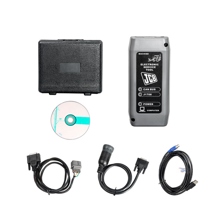
JCB Product Support Laptop Based Diagnostic Tool Manual Download
JCB Diagnostic Trouble Codes Download
JCB flash codes list Download
JCB JS-Excavator’s Fault Codes List Download
JCB v8+ Electrical Error Fault codes v1-07 Download
Troubleshooting/fault code,error kode JCB Excavator JS 200 JS 210 JS 220 JS 240 JS 260 Download
Livelink is a monitoring system that allows you to check the condition of equipment from anywhere in the world.
A special adapter connects to the equipment and transmits data to the JCB site via satellites and the cellular network, so that at any time, wherever you are, you can go to the site and find out
the current state of the observed JCB equipment.
In the GENERAL category, you can view help information, DLA adapter settings, Servicemaster program manual, as well as additional programs for diagnostics of
engines, transmissions and hydrostatic systems of such machines as FASTRAC T4 tractors, TELETRUK LPG loaders, Loadall 532H-537H telehandlers.
In order to start diagnostics or other procedures, you need to select the type of equipment from the corresponding category.
And then select the desired procedure from the available ones. For most types of equipment, in addition to diagnostics, you can configure the blocks, download new firmware and updates, view the
service history, decode error codes, do various tests, detailed help is also available in which you can see the location of components and wiring diagrams.
Please note that the list of available options for different types and models of equipment is different!
JCB Diagnostic Kit (DLA) is a multifunctional dealer scanner that reads diagnostic trouble codes, ranking them according to the degree of need for service on JCB equipment.
Main functional features:
reads fault codes and ranks them in order of importance.
calibrates, parameters and programs ECM units.
carries out a reset of service intervals.
Compatible with Jcb Service Master 2 software.
works with CAN protocol in OBD II system.
supplied with instructions for operation, repair and diagnostics of JCB equipment and engines Isuzu, Deutz, Cummins.
JCB Diagnostic Kit (DLA) Applicability
JCB agricultural machinery
Fastrac tractors (2000-3000, 3000 2 Series, 3000 Series 3, 7000-Series, 8250-Series 1, 8250 3 Series, 8000-Series 3).
Telescopic handlers (2007 -, 2007 +).
Wheeled backhoe loaders (Large, Large 2012+, Compact).
JC construction machinery
Backhoe loaders, tracked excavators (JS / JZ, JZ70).
Wheeled excavators, compact excavators (Mini / Midi) (801-8065, 8080-8085).
Telescopic handlers (2007 -, 2007 +).
Skidsteer loaders (Robot and others).
Telescopic handlers Teletrucks.
Wheeled backhoe loaders (Large, Large 2012+, Compact).
Frontal loaders.
Vibrating rollers.
Rough terrain forklifts.
JCB engines
JCB Dieselmax (MPS, OEM Base, G Drive).
JCB Ecomax (MPS, OEM Base, G Drive).
Equipment
JCB Diagnostic Kit (DLA) scanner.
USB cable.
DB9 cable.
9-pin adapter for German equipment.
8-pin cable.
JCB ServiceMaster 2 v10.3.1 software.
JCB Compact Service Manuals v50 [2011] (S1, S2, S3, S4, S5).
|
Tracked & Wheeled Excavators |
Extracted fromVersion 145 |
No of Error Codes in list 978 |
|
J1939 |
In Use? |
Reviewed/ |
Diagnostic Trouble |
Machine Reaction |
Extended Fault Text (Datalogger/Diagnostic Tools) |
|
0x00 |
Y |
55 |
P0001 |
Torque Reduction |
IMV driver fault is detected |
|
0x00 |
Y |
55 |
P0002 |
Torque Reduction |
Rail Pressure Negative Control Error During ‘IMV-Only’ control. PID controller not able to stabilise the |
|
0x00 |
Y |
55 |
P0002 |
Torque Reduction |
Rail pressure control error (pressure error too high). |
|
0x00 |
Y |
55 |
P0002 |
Delayed Engine Stop |
Rail Pressure Positive Control Error During ‘IMV-Only’ control. PID controller not able to stabilise the |
|
0x00 |
Y |
55 |
P0002 |
Torque Reduction |
Rail pressure control error (pressure error too low). |
|
0x00 |
Y |
55 |
P0003 |
Rail pressure control feedback low error |
|
|
0x00 |
Y |
55 |
P0003 |
Torque Reduction |
IMV driver fault is detected |
|
0x00 |
Y |
55 |
P0004 |
Torque Reduction |
IMV driver fault is detected |
|
0x00 |
Y |
55 |
P0004 |
Torque Reduction |
Rail pressure control feedback high error |
|
0x00 |
Y |
124 |
P0016 |
Cam Sensor Phase Shift |
|
|
0x00 |
Y |
124 |
P0045 |
VNT Control Fault |
|
|
0x00 |
Y |
124 |
P0045 |
Turbo EVRV Fault |
|
|
0x3D |
Y |
114 |
P0070-81 |
CAN bus message error from engine ECU |
|
|
0x3D |
Y |
114 |
P0070-87 |
CAN bus message error from engine ECU |
|
|
0x3D |
Y |
114 |
P0071-87 |
CAN bus message error for environment temperature from engine ECU |
|
|
0x00 |
Y |
55 |
P007A |
Torque Reduction |
TMAP (Intake Manifold 1 temp) Temperature Element sensor fault (ADC) |
|
0x00 |
Y |
55 |
P007C |
Torque Reduction |
TMAP (Intake Manifold 1 temp) Temperature Element sensor low fault |
|
0x00 |
Y |
55 |
P007D |
Torque Reduction |
TMAP (Intake Manifold 1 temp) Temperature Element sensor high fault |
|
0x00 |
Y |
55 |
P007E |
Torque Reduction |
TMAP (Intake Manifold 1 temp) Temperature Element sensor noise fault |
|
0x00 |
Y |
114 |
P0087 |
Torque Reduction |
Rail Pressure Control Error Positive |
|
0x00 |
Y |
55 |
P0087 |
Rail Pressure build low fault |
|
|
0x00 |
Y |
114 |
P0087 |
Rail Pressure build normal fault |
|
|
0x00 |
Y |
114 |
P0087 |
Torque Reduction_Delayed Engine Stop |
RPC Variable Limit Capacity (VLC) Torque reduction clamped |
|
0x00 |
Y |
124 |
P0087 |
Torque Reduction_Delayed Engine Stop |
Pressure Limiter Open |
|
0x00 |
Y |
114 |
P0087 |
Torque Reduction |
RPC Variable Limit Capacity (VLC) Torque reduction above its threshold |
|
0x00 |
Y |
114 |
P0088 |
Torque Reduction |
Rail pressure control error during HPV control (over max calibrated system pressure) |
|
0x00 |
Y |
114 |
P0088 |
Torque Reduction |
Rail pressure control error during IMV control (over max calibrated system pressure) |
|
0x00 |
Y |
55 |
P0088 |
Torque Reduction |
Rail pressure control undefined error (over max calibrated system pressure) |
|
0x00 |
Y |
114 |
P0088 |
Rail Pressure Control Error Negative |
|
|
0x00 |
Y |
124 |
P0088 |
Torque Reduction |
C/Rail pressure exceeds hi upper limit3 |
|
0x00 |
Y |
114 |
P0088 |
Rail Pressure overpressure timeout |
|
|
0x00 |
Y |
124 |
P0088 |
Torque Reduction |
Common Rail Pressure Rise㸦 1st Stage㸧 |
|
0x00 |
Y |
114 |
P0089 |
Rail Pressure control error |
|
|
0x00 |
Y |
114 |
P0089 |
Rail Pressure Negative Control Error During ‘HPV-Only’ control. PID controller not able to stabilise the |
|
0x00 |
Y |
114 |
P0089 |
Rail Pressure Positive Control Error During ‘HPV-Only’ control. PID controller not able to stabilise the |
|
|
0x00 |
Y |
55 |
P0089 |
Rail Pressure Negative Control Error During ‘IC & HMV’ control. PID controller not able to stabilise the |
|
|
0x00 |
Y |
114 |
P0089 |
Rail Pressure Positive Control Error During ‘IC & HMV’ control. PID controller not able to stabilise the |
|
|
0x00 |
Y |
114 |
P0089 |
Torque Reduction |
Rail Pressure Negative Control Error During ‘RVD-Only’ control. PID controller not able to stabilise the |
|
0x00 |
Y |
114 |
P0089 |
Delayed Engine Stop |
Rail Pressure Positive Control Error During ‘RVD-Only’ control. PID controller not able to stabilise the |
|
0x00 |
Y |
114 |
P0089 |
Torque Reduction |
Check that HPV is not stuck during IMV regulation. |
|
0x00 |
Y |
114 |
P0089 |
Torque Reduction |
HPV open loop slope fault detected |
|
0x00 |
Y |
124 |
P0089 |
Common Rail Pressure Fault (Excess Feed) |
|
|
0x00 |
Y |
55 |
P0090 |
Torque Reduction |
HPV driver in ECU fault detected |
|
0x00 |
Y |
55 |
P0091 |
Torque Reduction |
Check HPV regulation control trim low |
|
0x00 |
Y |
114 |
P0091 |
Torque Reduction |
Check HPV hardware current control trim low |
|
0x00 |
Y |
114 |
P0091 |
Torque Reduction |
HPV current feedback low fault detected |
|
0x00 |
Y |
124 |
P0091 |
Torque Reduction |
SCV Low Voltage Fault |
|
0x00 |
Y |
114 |
P0091 |
Torque Reduction |
HPV driver in ECU fault detected |
|
0x00 |
Y |
55 |
P0092 |
Torque Reduction |
Check HPV regulation control trim high. |
|
0x00 |
Y |
124 |
P0092 |
Torque Reduction_Delayed Engine Stop |
SCV High Voltage Fault |
|
0x00 |
Y |
114 |
P0092 |
Torque Reduction |
Check HPV hardware current control trim high |
|
0x00 |
Y |
114 |
P0092 |
Torque Reduction_Delayed Engine Stop |
HPV current feedback high fault detected |
|
0x00 |
Y |
114 |
P0092 |
Torque Reduction_Delayed Engine Stop |
HPV driver in ECU fault detected |
|
0x00 |
Y |
124 |
P0093 |
Common Rail Pressure Fall (No Feed) |
|
|
0x00 |
Y |
124 |
P0093 |
Common Rail Pressure Fault (Lack of Feed 2) |
|
|
0x00 |
Y |
55 |
P0095 |
Torque Reduction |
Intake manifold temperature (M2) signal sensor ADC fault (Intake Manifold 2 temp) |
|
0x00 |
Y |
55 |
P0096 |
Torque Reduction |
Intake manifold temperature sensor (M2) signal noise fault (Intake Manifold 2 temp) |
|
0x00 |
Y |
55 |
P0096 |
Torque Reduction |
Intake manifold temperature sensor (M2) signal plausibility fault (Intake Manifold 2 temp) |
|
0x00 |
Y |
55 |
P0097 |
Torque Reduction |
Intake manifold temperature sensor (M2) signal low fault (Intake Manifold 2 temp) |
|
0x00 |
Y |
55 |
P0098 |
Torque Reduction |
Intake manifold temperature sensor (M2) signal high signal fault (Intake Manifold 2 temp) |
|
0x3D |
Y |
114 |
P00B7-87 |
T4F Inducement |
CAN bus message error for coolant sensor from engine ECU |
|
0x00 |
Y |
55 |
P0100 |
Torque Reduction |
AMF High Side Driver fault Short Circuit To Ground (SC2G) |
|
0x00 |
Y |
114 |
P0100 |
Torque Reduction |
AMF fault (global). Set if plau, grad or electrical flt is present |
|
0x00 |
Y |
114 |
P0100 |
Torque Reduction |
AMF High Side Driver fault (Global |
|
0x00 |
Y |
114 |
P0100 |
Torque Reduction |
AMF High Side Driver fault Open Circuit (OC) Or Short Circuit to Battery (SC2VBAT) |
|
0x00 |
Y |
114 |
P0100 |
Torque Reduction |
AMF High Side Driver fault Short Circuit (SC) |
|
0x00 |
Y |
114 |
P0100 |
Torque Reduction |
AMF electrical sensor fault (ADC) |
|
0x00 |
Y |
124 |
P0101 |
MAF Sensor Fault |
|
|
0x00 |
Y |
124 |
P0102 |
Torque Reduction |
MAF Low Voltage Fault |
|
0x00 |
Y |
55 |
P0102 |
Torque Reduction |
AMF electrical sensor low fault |
|
0x00 |
Y |
124 |
P0103 |
Torque Reduction |
MAF High Voltage Fault |
|
0x00 |
Y |
55 |
P0103 |
Torque Reduction |
AMF electrical sensor high fault |
|
0x00 |
Y |
55 |
P0105 |
Torque Reduction |
Intake Manifold Absolute Pressure (MAP) sensor global fault |
|
0x00 |
Y |
55 |
P0106 |
Torque Reduction |
Intake Manifold Absolute Pressure (MAP) sensor signal drift low fault |
|
0x00 |
Y |
55 |
P0106 |
Torque Reduction |
Intake Manifold Absolute Pressure (MAP) sensor signal drift high fault |
|
0x00 |
Y |
55 |
P0106 |
Torque Reduction |
Intake Manifold Absolute Pressure (MAP) sensor signal plausibility fault |
|
0x00 |
Y |
55 |
P0106 |
Torque Reduction |
Intake Manifold Absolute Pressure (MAP) sensor signal plausibility high fault |
|
0x00 |
Y |
55 |
P0106 |
Torque Reduction |
Intake Manifold Absolute Pressure (MAP) sensor signal plausibility low fault |
|
0x00 |
Y |
124 |
P0107 |
Boost Pressure Sensor Fault 㸦 Low Voltage Fault |
|
|
0x00 |
Y |
124 |
P0108 |
Boost Pressure Sensor Fault 㸦 High Voltage Fault㸧 |
|
|
0x00 |
Y |
55 |
P0110 |
Torque Reduction |
Inlet Air Temperature (IAT) sensor signal ADC fault detected |
|
0x00 |
Y |
124 |
P0112 |
Torque Reduction |
Inlet Air Temperature (IAT) sensor signal low fault detected |
|
0x00 |
Y |
124 |
P0113 |
Torque Reduction |
Inlet Air Temperature (IAT) sensor signal high fault detected |
|
0x00 |
Y |
55 |
P0115 |
Torque Reduction |
Coolant sensor signal fault |
|
0x00 |
Y |
55 |
P0116 |
Coolant sensor fault (plausibility) |
|
|
0x00 |
Y |
124 |
P0116 |
Torque Reduction |
Coolant temperature sensor performance invalid |
|
0x00 |
Y |
55 |
P0117 |
Coolant sensor signal low fault |
|
|
0x00 |
Y |
124 |
P0117 |
Coolant temperature sensor signal too low |
|
|
0x00 |
Y |
124 |
P0118 |
Coolant sensor signal high fault |
|
|
0x00 |
Y |
124 |
P0122 |
Intake Throttle Position Low Voltage Fault |
|
|
0x00 |
Y |
124 |
P0123 |
Intake Throttle Position High Voltage Fault |
|
|
0x3D |
Y |
114 |
P0129-87 |
Erroneous signal for Barometric Pressure. |
|
|
0x3D |
Y |
114 |
P0129-87 |
CAN bus message error for environment pressure from engine ECU |
|
|
0x00 |
Y |
55 |
P0133 |
Wide Range Air Fuel control (WRAF) fault: Response |
|
|
0x00 |
Y |
55 |
P0180 |
Torque Reduction |
Fuel temperature ADC fault |
|
J1939 |
In Use? |
Added |
Diagnostic Trouble |
Machine Reaction |
Extended Fault Text (Datalogger/Diagnostic Tools) |
|
0x00 |
Y |
124 |
P0181 |
Torque Reduction |
Fuel Temperature Sensor Fault |
|
0x00 |
Y |
55 |
P0181 |
Torque Reduction |
Fuel temperature sensor gradient fault |
|
0x3D |
Y |
114 |
P0181-87 |
CAN bus message error for fuel temperature from engine ECU |
|
|
0x00 |
Y |
124 |
P0182 |
Torque Reduction |
Fuel temperature sensor low fault |
|
0x00 |
Y |
124 |
P0183 |
Torque Reduction |
Fuel temperature sensor high fault |
|
0x00 |
Y |
55 |
P0190 |
Torque Reduction_Limp Home (Idle Only) |
Rail Pressure Sensor signal grad fault |
|
0x00 |
Y |
55 |
P0191 |
Torque Reduction_Limp Home (Idle Only) |
Rail Pressure Sensor fault. Above maximum threshold (out of range at key-on) |
|
0x00 |
Y |
55 |
P0191 |
Torque Reduction_Limp Home (Idle Only) |
Rail Pressure Sensor fault. Below minimum threshold (out of range at key-on) |
|
0x00 |
Y |
55 |
P0191 |
Torque Reduction_Limp Home (Idle Only) |
Rail Pressure Sensor fault. Exceeds threshold (out of range at key-on) |
|
0x00 |
Y |
124 |
P0192 |
Torque Reduction_Limp Home (Idle Only) |
Rail Pressure Sensor signal low fault |
|
0x00 |
Y |
124 |
P0193 |
Torque Reduction_Limp Home (Idle Only) |
Rail Pressure Sensor signal high fault |
|
0x00 |
Y |
55 |
P0194 |
Torque Reduction_Limp Home (Idle Only)_Delayed |
Rail Pressure Sensor signal drop fault |
|
0x00 |
Y |
55 |
P0195 |
Torque Reduction |
Oil temperature sensor signal global fault |
|
0x00 |
Y |
114 |
P0195 |
Torque Reduction |
Oil temperature sensor signal external voltage (V-Ref) fault |
|
0x00 |
Y |
55 |
P0196 |
Torque Reduction |
Oil temperature sensor signal plausability fault |
|
0x00 |
Y |
55 |
P0196 |
Torque Reduction |
Oil temperature sensor signal gradient fault |
|
0x3D |
Y |
114 |
P0196-87 |
CAN bus message error for oil temperature from engine ECU |
|
|
0x00 |
Y |
55 |
P0197 |
Torque Reduction |
Oil temperature sensor signal low fault |
|
0x00 |
Y |
55 |
P0198 |
Torque Reduction |
Oil temperature sensor signal high fault |
|
0x00 |
Y |
55 |
P0201 |
Injector 2 Open Circuit fault (OC) |
|
|
0x00 |
Y |
55 |
P0201 |
Injector in Cylinder 1 Short Circuit HSD to LSD |
|
|
0x00 |
Y |
124 |
P0201 |
Injector in Cylinder 1 Open Circuit fault (OC) |
|
|
0x00 |
Y |
124 |
P0202 |
Injector 1 Open Circuit fault (OC) |
|
|
0x00 |
Y |
55 |
P0202 |
Injector in Cylinder 2 Short Circuit HSD to LSD |
|
|
0x00 |
Y |
88 |
P0202 |
Injector in Cylinder 2 Open Circuit fault (OC) |
|
|
0x00 |
Y |
124 |
P0203 |
Injector 3 Open Circuit fault (OC) |
|
|
0x00 |
Y |
55 |
P0203 |
Injector in Cylinder 3 Short Circuit HSD to LSD |
|
|
0x00 |
Y |
88 |
P0203 |
Injector in Cylinder 3 Open Circuit fault (OC) |
|
|
0x00 |
Y |
124 |
P0204 |
Injector 0 Open Circuit fault (OC) |
|
|
0x00 |
Y |
55 |
P0204 |
Injector in Cylinder 4 Short Circuit HSD to LSD |
|
|
0x00 |
Y |
88 |
P0204 |
Injector in Cylinder 4 Open Circuit fault (OC) |
|
|
0x00 |
Y |
124 |
P0205 |
Injector in Cylinder 5 Open Circuit fault (OC) |
|
|
0x00 |
Y |
88 |
P0205 |
Injector in Cylinder 5 Short Circuit HSD to LSD |
|
|
0x00 |
Y |
124 |
P0206 |
Injector in Cylinder 6 Open Circuit fault (OC) |
|
|
0x00 |
Y |
88 |
P0206 |
Injector in Cylinder 6 Short Circuit HSD to LSD |
|
|
0x00 |
Y |
124 |
P0217 |
Torque Reduction |
Coolant temperature exceeds upper limit |
|
0x00 |
Y |
124 |
P0219 |
Torque Reduction |
Engine overspeed condition |
|
0x00 |
Y |
124 |
P0234 |
Torque Reduction |
Turbo Over Boost |
|
0x00 |
Y |
55 |
P0235 |
Torque Reduction |
Boosted air pressure sensor fault: ADC |
|
0x00 |
Y |
55 |
P0237 |
Torque Reduction |
Boosted air pressure sensor low fault |
|
0x00 |
Y |
55 |
P0238 |
Torque Reduction |
Boosted air pressure sensor high fault |
|
0x00 |
Y |
55 |
P0252 |
Torque Reduction |
Rail pressure control error (IMV current trim drift). |
|
0x00 |
Y |
114 |
P0252 |
Torque Reduction |
Rail pressure control error (IMV current trim drift). |
|
0x00 |
Y |
114 |
P0252 |
Torque Reduction |
Rail pressure control error (IMV current trim drift). |
|
0x00 |
Y |
114 |
P0252 |
Torque Reduction |
Rail pressure control error (IMV current trim drift). |
|
0x00 |
Y |
114 |
P0252 |
Torque Reduction |
Rail pressure control error (IMV current trim drift). |
|
0x00 |
Y |
55 |
P0253 |
Torque Reduction_Delayed Engine Stop |
Rail pressure control by the IMV. Occurs at high fuel delivery for low (negative) current trim |
|
0x00 |
Y |
55 |
P0254 |
Torque Reduction_Delayed Engine Stop |
Rail pressure control fault by the IMV. Occurs at high fuel delivery for high (positive) current trim |
|
0x00 |
Y |
55 |
P0261 |
Torque Reduction |
Injector and wiring harness resistance too high/low (inj 2) |
|
0x00 |
Y |
55 |
P0261 |
Torque Reduction |
Injector and wiring harness resistance too high/low (inj 2) |
|
0x00 |
Y |
55 |
P0262 |
Torque Reduction |
Injector and wiring harness resistance drop (Inj 2) |
|
0x00 |
Y |
55 |
P0262 |
Torque Reduction |
Injector and wiring harness resistance drop (Inj 2) |
|
0x00 |
Y |
55 |
P0263 |
Torque Reduction |
Cylinder balancing fault injector 2 stuck closed |
|
0x00 |
Y |
55 |
P0264 |
Torque Reduction |
Injector and wiring harness resistance too high/low (inj 1) |
|
0x00 |
Y |
55 |
P0264 |
Torque Reduction |
Injector and wiring harness resistance too high/low (inj 1) |
|
0x00 |
Y |
55 |
P0265 |
Torque Reduction |
Injector and wiring harness resistance drop (Inj 1) |
|
0x00 |
Y |
55 |
P0265 |
Torque Reduction |
Injector and wiring harness resistance drop (Inj 1) |
|
0x00 |
Y |
55 |
P0266 |
Torque Reduction |
Cylinder balancing fault injector 1 stuck closed |
|
0x00 |
Y |
55 |
P0267 |
Torque Reduction |
Injector and wiring harness resistance too high/low (inj 3) |
|
0x00 |
Y |
55 |
P0267 |
Torque Reduction |
Injector and wiring harness resistance too high/low (inj 3) |
|
0x00 |
Y |
55 |
P0268 |
Torque Reduction |
Injector and wiring harness resistance drop (Inj 3) |
|
0x00 |
Y |
55 |
P0268 |
Torque Reduction |
Injector and wiring harness resistance drop (Inj 3) |
|
0x00 |
Y |
55 |
P0269 |
Torque Reduction |
Cylinder balancing fault injector 3 stuck closed |
|
0x00 |
Y |
55 |
P0270 |
Torque Reduction |
Injector drift fault detection on Injector 2. Fault which is set when the Injector 2 MDP trim exceeds the |
|
0x00 |
Y |
55 |
P0270 |
Torque Reduction |
Injector drift fault detection on Injector 2. Fault which is set when Injector 2 MDP trim exceeds the |
|
0x00 |
Y |
55 |
P0271 |
Torque Reduction |
Injector and wiring harness resistance drop (Inj 0) |
|
0x00 |
Y |
55 |
P0271 |
Torque Reduction |
Injector and wiring harness resistance drop (Inj 0) |
|
0x00 |
Y |
55 |
P0272 |
Torque Reduction |
Cylinder balancing fault injector 0 stuck closed |
|
0x00 |
Y |
88 |
P0273 |
Injector and wiring harness resistance too high/low (inj 1) |
|
|
0x00 |
Y |
88 |
P0273 |
Injector and wiring harness resistance too high/low (inj 1) |
|
|
0x00 |
Y |
88 |
P0274 |
Injector and wiring harness resistance drop (Inj 1) |
|
|
0x00 |
Y |
88 |
P0274 |
Injector and wiring harness resistance drop (Inj 1) |
|
|
0x00 |
Y |
88 |
P0275 |
Cylinder balancing fault injector 1 stuck closed |
|
|
0x00 |
Y |
88 |
P0276 |
Injector and wiring harness resistance too high/low (inj 3) |
|
|
0x00 |
Y |
88 |
P0276 |
Injector and wiring harness resistance too high/low (inj 3) |
|
|
0x00 |
Y |
88 |
P0277 |
Injector and wiring harness resistance drop (Inj 3) |
|
|
0x00 |
Y |
88 |
P0277 |
Injector and wiring harness resistance drop (Inj 3) |
|
|
0x00 |
Y |
88 |
P0278 |
Cylinder balancing fault injector 3 stuck closed |
|
|
0x00 |
Y |
124 |
P0299 |
Torque Reduction |
Turbo Low Boost |
|
0x00 |
Y |
55 |
P029A |
Injector drift fault detection on Injector 3. Fault which is set when the Injector 3 MDP trim exceeds the |
|
|
0x00 |
Y |
55 |
P029A |
Injector drift fault detection on Injector 2. Fault which is set when the Injector 2 MDP trim exceeds the |
|
|
0x00 |
Y |
55 |
P029A |
Injector drift fault detection on Injector 2. Fault which is set when Injector 2 MDP trim exceeds the |
|
|
0x00 |
Y |
55 |
P029B |
Fault which is set when the Injector 3 absolute MDP value is below a calibrated threshold |
|
|
0x00 |
Y |
55 |
P029B |
Injector drift fault detection on Injector 2. Fault which is set when Injector 2 MDP trim exceeds the |
|
|
0x00 |
Y |
55 |
P029B |
Injector drift fault detection on Injector 2. Fault which is set when Injector 2 MDP trim exceeds the |
|
|
0x00 |
Y |
55 |
P029B |
Injector drift fault detection on Injector 2. Fault which is set when Injector 2 MDP trim exceeds the |
|
J1939 |
In Use? |
Added |
Diagnostic Trouble |
Machine Reaction |
Extended Fault Text (Datalogger/Diagnostic Tools) |
|
0x00 |
Y |
55 |
P029E |
Injector drift fault detection on Injector 1. Fault which is set when the Injector 1 MDP trim exceeds the |
|
|
0x00 |
Y |
55 |
P029E |
Injector drift fault detection on Injector 1. Fault which is set when the Injector 1 MDP trim exceeds the |
|
|
0x00 |
Y |
55 |
P029E |
Injector drift fault detection on Injector 1. Fault which is set when Injector 1 MDP trim exceeds the |
|
|
0x00 |
Y |
55 |
P029F |
Fault which is set when the Injector 2 absolute MDP value is below a calibrated threshold |
|
|
0x00 |
Y |
55 |
P029F |
Injector drift fault detection on Injector 1. Fault which is set when Injector 1 MDP trim exceeds the |
|
|
0x00 |
Y |
55 |
P029F |
Injector drift fault detection on Injector 1. Fault which is set when Injector 1 MDP trim exceeds the |
|
|
0x00 |
Y |
55 |
P029F |
Injector drift fault detection on Injector 1. Fault which is set when Injector 1 MDP trim exceeds the |
|
|
0x00 |
Y |
55 |
P02A2 |
Injector drift fault detection on Injector 2. Fault which is set when the Injector 2 MDP trim exceeds the |
|
|
0x00 |
Y |
55 |
P02A2 |
Injector drift fault detection on Injector 2. Fault which is set when the Injector 2 MDP trim exceeds the |
|
|
0x00 |
Y |
55 |
P02A2 |
Injector drift fault detection on Injector 2. Fault which is set when Injector 2 MDP trim exceeds the |
|
|
0x00 |
Y |
55 |
P02A3 |
Fault which is set when the Injector 4 absolute MDP value is below a calibrated threshold |
|
|
0x00 |
Y |
55 |
P02A3 |
Injector drift fault detection on Injector 3. Fault which is set when Injector 3 MDP trim exceeds the |
|
|
0x00 |
Y |
55 |
P02A3 |
Injector drift fault detection on Injector 3. Fault which is set when Injector 3 MDP trim exceeds the |
|
|
0x00 |
Y |
55 |
P02A3 |
Injector drift fault detection on Injector 3. Fault which is set when Injector 3 MDP trim exceeds the |
|
|
0x00 |
Y |
55 |
P02A6 |
Injector drift fault detection on Injector 0. Fault which is set when the Injector 0 MDP trim exceeds the |
|
|
0x00 |
Y |
55 |
P02A6 |
Injector drift fault detection on Injector 0. Fault which is set when the Injector 0 MDP trim exceeds the |
|
|
0x00 |
Y |
55 |
P02A6 |
Injector drift fault detection on Injector 0. Fault which is set when Injector 0 MDP trim exceeds the |
|
|
0x00 |
Y |
55 |
P02A7 |
Fault which is set when the Injector 1 absolute MDP value is below a calibrated threshold |
|
|
0x00 |
Y |
55 |
P02A7 |
Injector drift fault detection on Injector 0. Fault which is set when Injector 0 MDP trim exceeds the |
|
|
0x00 |
Y |
55 |
P02A7 |
Injector drift fault detection on Injector 0. Fault which is set when Injector 0 MDP trim exceeds the |
|
|
0x00 |
Y |
55 |
P02A7 |
Injector drift fault detection on Injector 0. Fault which is set when Injector 0 MDP trim exceeds the |
|
|
0x00 |
Y |
88 |
P02AA |
Injector drift fault detection on Injector 1. Fault which is set when the Injector 1 MDP trim exceeds the |
|
|
0x00 |
Y |
88 |
P02AA |
Injector drift fault detection on Injector 1. Fault which is set when the Injector 1 MDP trim exceeds the |
|
|
0x00 |
Y |
88 |
P02AA |
Injector drift fault detection on Injector 1. Fault which is set when Injector 1 MDP trim exceeds the |
|
|
0x00 |
Y |
88 |
P02AB |
Fault which is set when the Injector 1 absolute MDP value is below a calibrated threshold |
|
|
0x00 |
Y |
88 |
P02AB |
Injector drift fault detection on Injector 1. Fault which is set when Injector 1 MDP trim exceeds the |
|
|
0x00 |
Y |
88 |
P02AB |
Injector drift fault detection on Injector 1. Fault which is set when Injector 1 MDP trim exceeds the |
|
|
0x00 |
Y |
88 |
P02AB |
Injector drift fault detection on Injector 1. Fault which is set when Injector 1 MDP trim exceeds the |
|
|
0x00 |
Y |
88 |
P02AE |
Injector drift fault detection on Injector 3. Fault which is set when the Injector 3 MDP trim exceeds the |
|
|
0x00 |
Y |
88 |
P02AE |
Injector drift fault detection on Injector 3. Fault which is set when the Injector 3 MDP trim exceeds the |
|
|
0x00 |
Y |
88 |
P02AE |
Injector drift fault detection on Injector 3. Fault which is set when Injector 3 MDP trim exceeds the |
|
|
0x00 |
Y |
88 |
P02AF |
Fault which is set when the Injector 3 absolute MDP value is below a calibrated threshold |
|
|
0x00 |
Y |
88 |
P02AF |
Injector drift fault detection on Injector 3. Fault which is set when Injector 3 MDP trim exceeds the |
|
|
0x00 |
Y |
88 |
P02AF |
Injector drift fault detection on Injector 3. Fault which is set when Injector 3 MDP trim exceeds the |
|
|
0x00 |
Y |
88 |
P02AF |
Injector drift fault detection on Injector 3. Fault which is set when Injector 3 MDP trim exceeds the |
|
|
0x3D |
Y |
114 |
P0321-87 |
CAN bus message error for engine speed from engine ECU |
|
|
0x00 |
Y |
55 |
P0325 |
Accelerometer fault (signal/noise ratio too low in idle) |
|
|
0x00 |
Y |
94 |
P0330 |
Knock Sensor 1 Circuit |
|
|
0x00 |
Y |
124 |
P0335 |
Crank Sensor Fault 㸦 No Signal㸧 |
|
|
0x00 |
Y |
55 |
P0335 |
Crankshaft Position Sensor «A» Circuit |
|
|
0x00 |
Y |
114 |
P0335 |
Crank signal overspeed fault |
|
|
0x00 |
Y |
124 |
P0336 |
Torque Reduction |
Crank Sensor Fault 㸦 Signal Fault㸧 |
|
0x00 |
Y |
55 |
P0340 |
Torque Reduction |
Cam signal last learnt value is outside of limits |
|
0x00 |
Y |
124 |
P0340 |
Torque Reduction |
G Sensor Fault (No Signal) |
|
0x00 |
Y |
55 |
P0341 |
Torque Reduction |
Cam signal drift higher than threshold |
|
0x00 |
Y |
124 |
P0341 |
Torque Reduction |
G Sensor Fault (Abnormal Signal㸧 |
|
0x00 |
Y |
55 |
P0341 |
Camshaft Position Sensor A Circuit Range / Performance |
|
|
0x00 |
Y |
55 |
P0341 |
Torque Reduction |
Cam signal lost (no Cam signal seen in 2 Crank rotations) |
|
0x00 |
Y |
55 |
P0341 |
Torque Reduction |
Cam signal fault (missing event within the expected window) |
|
0x00 |
Y |
55 |
P0341 |
Cam signal fault (overspeed detected) |
|
|
0x3D |
Y |
114 |
P0350-02 |
Error monitoring for system protection based on ignition switch input |
|
|
0x00 |
Y |
55 |
P0371 |
Torque Reduction |
Crank signal is too close to the previous one |
|
0x00 |
Y |
55 |
P0372 |
Torque Reduction |
Elapsed time between CPS events is too high |
|
0x00 |
Y |
55 |
P0374 |
Torque Reduction |
Crank signal lost (no CPS signal seen in 1 Cam rotation) |
|
0x00 |
Y |
124 |
P0380 |
Glow Plug/Heater Circuit «A» |
|
|
0x00 |
Y |
55 |
P0380 |
Glow Plug/Heater Circuit «A» |
|
|
0x00 |
Y |
124 |
P0381 |
Glow Plug Fault |
|
|
0x00 |
Y |
55 |
P0383 |
Glow Plug Control Module Control Circuit Low |
|
|
0x00 |
Y |
55 |
P0384 |
Glow Plug Control Module Control Circuit High |
|
|
0x00 |
Y |
55 |
P0400 |
Torque Reduction / T4F Inducement |
EGR flow reached its limit |
|
0x00 |
Y |
124 |
P0401 |
EGR Gas flow Fault |
|
|
0x00 |
Y |
124 |
P0404 |
EGR Valve Control Fault |
|
|
0x00 |
Y |
124 |
P0404 |
EGR Open Defective |
|
|
0x00 |
Y |
94 |
P0404 |
Exhaust Gas Recirculation «A» Control Circuit Range/Performance |
|
|
0x00 |
Y |
55 |
P0405 |
Exhaust Gas Recirculation Sensor «A» Circuit Low |
|
|
0x00 |
Y |
55 |
P0406 |
Exhaust Gas Recirculation Sensor «A» Circuit High |
|
|
0x00 |
Y |
124 |
P0409 |
EGR Position Sensor Fault 㸦 Brushless Specification㸧 |
|
|
0x00 |
Y |
124 |
P041C |
Manifold Temperature Sensor Fault 㸦 High Voltage |
|
|
0x00 |
Y |
124 |
P041D |
Manifold Temperature Sensor Fault 㸦 Low Voltage Fault㸧 |
|
|
0x00 |
Y |
124 |
P0426 |
DPF Exhaust Temperature 1 High |
|
|
0x00 |
Y |
124 |
P0426 |
DPF Exhaust Temperature 1Low |
|
|
0x00 |
Y |
124 |
P0427 |
Exhaust Temperature Sensor 1Low Voltage Fault |
|
|
0x00 |
Y |
124 |
P0428 |
Exhaust Temperature Sensor 1High Voltage Fault |
|
|
0x00 |
Y |
124 |
P042B |
DPF Exhaust Temperature 2 High |
|
|
0x00 |
Y |
124 |
P042B |
DPF Exhaust Temperature 2 Low |
|
|
0x00 |
Y |
124 |
P042C |
Exhaust Temperature Sensor 2 Low Voltage Fault |
|
|
0x00 |
Y |
124 |
P042D |
Exhaust Temperature Sensor 2 High Voltage Fault |
|
|
0x00 |
Y |
94 |
P046D |
Exhaust Gas Recirculation Sensor «A» Circuit Intermittent/Erratic |
|
|
0x00 |
Y |
55 |
P0470 |
Torque Reduction |
Exhaust manifold pressure (P3) signal ADC fault |
|
0x00 |
Y |
55 |
P0472 |
Torque Reduction |
Exhaust manifold pressure (P3) signal low fault |
|
0x00 |
Y |
55 |
P0472 |
Torque Reduction |
Exhaust manifold pressure (P3) signal drifted low |
|
0x00 |
Y |
55 |
P0473 |
Torque Reduction |
Exhaust manifold pressure (P3) signal high fault |
|
0x00 |
Y |
55 |
P0473 |
Torque Reduction |
Exhaust manifold pressure (P3) signal drifted high |
|
0x00 |
Y |
124 |
P0512 |
Starter Switch Fault |
|
|
0x00 |
Y |
55 |
P0520 |
Low oil pressure Lamp/Gauge drive open circuit (OC) |
|
|
0x00 |
Y |
55 |
P0520 |
Low oil pressure Lamp/Gauge drive short circuit (SC) |
|
|
0x00 |
Y |
55 |
P0520 |
Low oil pressure Lamp/Gauge drive short circuit to ground (SC2GND) |
|
|
0x00 |
Y |
55 |
P0520 |
Low oil pressure Lamp/Gauge drive short circuit to battery voltage (SC2VBATT) |
|
|
0x00 |
Y |
55 |
P0521 |
Oil pressure sensor signal global fault |
|
|
0x00 |
Y |
124 |
P0522 |
None |
Engine Oil Pressure Sensor Fault (Low Voltage Fault) |
|
0x00 |
Y |
88 |
P0522 |
Torque Reduction |
Oil Pressure Signal Out of Range High |
|
0x00 |
Y |
55 |
P0522 |
High Oil Pressure During Engine Running |
|
|
0x00 |
Y |
55 |
P0523 |
Low Oil Pressure During Engine Running |
|
|
0x27 |
Y |
91 |
P0523 |
Low Oil Pressure During Engine Running |
|
|
0x00 |
Y |
124 |
P0523 |
Engine Oil Pressure Sensor Fault (High Voltage Fault) |
|
|
0x00 |
Y |
88 |
P0523 |
Torque Reduction |
Oil Pressure Signal Out of Range Low |
|
0x00 |
Y |
88 |
P0523 |
Low Oil Pressure During Engine Running |
|
|
0x00 |
Y |
55 |
P0544 |
Torque Reduction |
Turbo in temperature fault |
|
0x00 |
Y |
55 |
P0545 |
Torque Reduction |
Turbo in temperature count low fault |
|
0x00 |
Y |
55 |
P0546 |
Torque Reduction |
Turbo in temperature count high fault |
|
0x00 |
Y |
124 |
P0560 |
12V Power Supply Voltage Fault |
|
|
0x00 |
Y |
55 |
P0562 |
Torque Reduction |
Battery voltage monitoring signal low fault |
|
0x00 |
Y |
124 |
P0562 |
Torque Reduction |
System Power Supply Low Voltage Fault |
|
0x3D |
Y |
114 |
P0562-16 |
Low battery voltage |
|
|
0x3D |
Y |
114 |
P0562-02 |
Fault due to low or high battery voltage supply to DCU |
|
|
0x00 |
Y |
55 |
P0563 |
Torque Reduction |
Battery voltage monitoring signal high fault |
|
0x00 |
Y |
124 |
P0563 |
Torque Reduction |
System Power Supply High Voltage Fault |
|
0x3D |
Y |
114 |
P0563-17 |
High battery voltage |
|
|
0x00 |
Y |
124 |
P0601 |
Torque Reduction |
ROM Fault |
|
0x00 |
Y |
124 |
P0602 |
Limp Home (Idle Only) |
QR Code Error |
|
0x00 |
Y |
114 |
P0602 |
Limp Home (Idle Only) |
C2I data not programmed |
|
0x00 |
Y |
55 |
P0602 |
Limp Home (Idle Only) |
C2I data not programmed |
|
0x00 |
Y |
114 |
P0602 |
Limp Home (Idle Only) |
C2I data not programmed |
|
0x00 |
Y |
114 |
P0602 |
Limp Home (Idle Only) |
C2I data not programmed |
|
0x00 |
Y |
114 |
P0602 |
Limp Home (Idle Only)_Engine Stop |
RAM corruption affecting Injector C2I data |
|
0x00 |
Y |
114 |
P0602 |
Functional Safety Fault |
|
|
0x00 |
Y |
55 |
P0602 |
Limp Home (Idle Only) |
Functional Safety Fault |
|
0x00 |
Y |
55 |
P0603 |
Engine Stop |
ECU memory integrity fault (data / cal integrity) |
|
0x00 |
Y |
55 |
P0604 |
Engine Stop |
ECU memory integrity fault (RAM integrity) |
|
0x00 |
Y |
124 |
P0604 |
Engine Stop |
RAM Fault |
|
0x00 |
Y |
55 |
P0605 |
Engine Stop |
ECU memory integrity fault (code integrity) |
|
0x00 |
Y |
55 |
P0606 |
Engine Stop |
Functional Safety Fault |
|
0x00 |
Y |
55 |
P0606 |
Engine Stop |
Functional Safety Fault |
|
0x00 |
Y |
55 |
P0606 |
Engine Stop |
Functional Safety Fault |
|
0x00 |
Y |
55 |
P0606 |
Engine Stop |
Functional Safety Fault |
|
0x00 |
Y |
55 |
P0606 |
Engine Stop |
Functional Safety Fault |
|
0x00 |
Y |
124 |
P0606 |
Engine Stop |
CPU Fault |
|
0x00 |
Y |
124 |
P0606 |
Engine Stop |
CPU Monitoring IC Fault |
|
0x00 |
Y |
55 |
P0606 |
Engine Stop |
Functional Safety Fault |
|
0x3D |
Y |
114 |
P0606-02 |
Peripheral monitoring error on DCU |
|
|
0x00 |
Y |
55 |
P0607 |
Engine Stop |
Functional Safety Fault |
|
0x00 |
Y |
55 |
P0607 |
Torque Reduction |
Throttle H-Bridge driver in ECU fault: Over temperature |
|
0x00 |
Y |
55 |
P060A |
Engine Stop |
Functional Safety Fault |
|
0x00 |
Y |
55 |
P060A |
Engine Stop |
Functional Safety Fault |
|
0x00 |
Y |
55 |
P060A |
Engine Stop |
Functional Safety Fault |
|
0x00 |
Y |
55 |
P060A |
Engine Stop |
Functional Safety Fault |
|
0x00 |
Y |
55 |
P060A |
Engine Stop |
Functional Safety Fault |
|
0x00 |
Y |
55 |
P060A |
Engine Stop |
Functional Safety Fault |
|
0x00 |
Y |
55 |
P060A |
Engine Stop |
Functional Safety Fault |
|
0x00 |
Y |
55 |
P060A |
Engine Stop |
Functional Safety Fault |
|
0x3D |
Y |
114 |
P060A-00 |
Monitoring error on DCU |
|
|
0x00 |
Y |
124 |
P060B |
A/D Conversion Fault |
|
|
0x00 |
Y |
55 |
P060B |
Limp Home (Idle Only)_Engine Stop |
ADC circuit fault (Global) |
|
0x00 |
Y |
55 |
P060B |
Torque Reduction |
HPV current feedback ADC fault detected |
|
0x00 |
Y |
55 |
P060B |
Internal Control Module A/D Processing Performance |
|
|
0x00 |
Y |
55 |
P060B |
Torque Reduction |
Functional Safety Fault |
|
SA (hex) |
In Use? |
Added |
Code |
Machine Reaction |
Extended Fault Text (Datalogger/Diagnostic Tools) |
|
0x00 |
Y |
55 |
P060B |
Torque Reduction |
Functional Safety Fault |
|
0x00 |
Y |
55 |
P060B |
Torque Reduction |
Functional Safety Fault |
|
0x00 |
Y |
55 |
P060C |
Engine Stop |
Functional Safety Fault |
|
0x00 |
Y |
55 |
P060C |
Engine Stop |
Functional Safety Fault |
|
0x00 |
Y |
55 |
P060C |
Engine Stop |
Functional Safety Fault |
|
0x00 |
Y |
55 |
P060C |
Engine Stop |
Functional Safety Fault |
|
0x00 |
Y |
55 |
P060C |
Engine Stop |
Functional Safety Fault |
|
0x00 |
Y |
55 |
P060C |
Engine Stop |
Functional Safety Fault |
|
0x00 |
Y |
55 |
P060C |
Engine Stop |
Functional Safety Fault |
|
0x00 |
Y |
55 |
P060C |
Engine Stop |
Functional Safety Fault |
|
0x00 |
Y |
55 |
P060C |
Engine Stop |
Functional Safety Fault |
|
0x3D |
Y |
114 |
P060C-00 |
DCU software reset performed |
|
|
0x3D |
Y |
114 |
P060C-41 |
T4F Inducement |
DCU software reset performed |
|
0x3D |
Y |
114 |
P060C-94 |
DCU software reset performed |
|
|
0x3D |
Y |
114 |
P060C-68 |
DCU software reset performed |
|
|
0x00 |
Y |
55 |
P060D |
Engine Stop |
Functional Safety Fault |
|
0x00 |
Y |
55 |
P060D |
Engine Stop |
Functional Safety Fault |
|
0x00 |
Y |
55 |
P060D |
Torque Reduction |
Functional Safety Fault |
|
0x00 |
Y |
55 |
P060D |
Torque Reduction |
Functional Safety Fault |
|
0x00 |
Y |
55 |
P060E |
Torque Reduction |
Functional Safety Fault |
|
0x00 |
Y |
55 |
P0612 |
Fuel Injector Control Module Relay Control |
|
|
0x00 |
Y |
55 |
P0612 |
Fuel Injector Control Module Relay Control |
|
|
0x00 |
Y |
55 |
P0612 |
Fuel Injector Control Module Relay Control |
|
|
0x00 |
Y |
55 |
P0612 |
Fuel Injector Control Module Relay Control |
|
|
0x00 |
Y |
124 |
P0615 |
Starter Relay Circuit |
|
|
0x00 |
Y |
55 |
P061A |
Functional Safety Fault |
|
|
0x00 |
Y |
55 |
P061B |
Torque Reduction |
Functional Safety Fault |
|
0x00 |
Y |
55 |
P061C |
Functional Safety Fault |
|
|
0x00 |
Y |
55 |
P061E |
Functional Safety Fault |
|
|
0x00 |
Y |
55 |
P061E |
Functional Safety Fault |
|
|
0x00 |
Y |
55 |
P0627 |
Torque Reduction |
Lift pump global fault |
|
0x00 |
Y |
55 |
P0628 |
Torque Reduction |
Lift pump global fault |
|
0x00 |
Y |
55 |
P0629 |
Torque Reduction |
Lift pump global fault |
|
0x00 |
Y |
55 |
P062B |
Torque Reduction |
Functional Safety Fault |
|
0x00 |
Y |
55 |
P062B |
Torque Reduction |
Functional Safety Fault |
|
0x00 |
Y |
55 |
P062B |
Torque Reduction |
Functional Safety Fault |
|
0x00 |
Y |
55 |
P062B |
Torque Reduction |
Functional Safety Fault |
|
0x00 |
Y |
55 |
P062B |
Torque Reduction |
Functional Safety Fault |
|
0x00 |
Y |
55 |
P062B |
Torque Reduction |
Functional Safety Fault |
|
0x00 |
Y |
55 |
P062B |
Torque Reduction |
Functional Safety Fault |
|
0x00 |
Y |
55 |
P062B |
Torque Reduction |
Functional Safety Fault |
|
0x00 |
Y |
55 |
P062B |
Torque Reduction |
Functional Safety Fault |
|
0x00 |
Y |
55 |
P062B |
Torque Reduction |
Functional Safety Fault |
|
0x00 |
Y |
55 |
P062B |
Torque Reduction |
Functional Safety Fault |
|
0x00 |
Y |
55 |
P062D |
Delayed Engine Stop |
Injector Bank 0 fault shorted to ground (SC2VBAT) |
|
0x00 |
Y |
55 |
P062D |
Delayed Engine Stop |
Injector Bank 0 fault shorted to ground (SC2GND) |
|
0x00 |
Y |
55 |
P062E |
Delayed Engine Stop |
Injector Bank 1 fault shorted to ground (SC2VBAT) |
|
0x00 |
Y |
55 |
P062E |
Delayed Engine Stop |
Injector Bank 1 fault shorted to ground (SC2GND) |
|
0x00 |
Y |
55 |
P062F |
Torque Reduction_Limp Home (Idle Only) |
ECU non volatile memory fault |
|
0x00 |
Y |
114 |
P062F |
Torque Reduction_Limp Home (Idle Only) |
ECU non volatile memory fault (C2I, MDP) |
|
0x00 |
Y |
114 |
P062F |
Torque Reduction_Limp Home (Idle Only) |
ECU non volatile memory fault (RP, PL, STE) |
|
0x00 |
Y |
114 |
P062F |
Torque Reduction_Limp Home (Idle Only) |
ECU non volatile memory fault (WDOG) |
|
0x00 |
Y |
114 |
P062F |
Torque Reduction_Limp Home (Idle Only) |
ECU non volatile memory fault (CAN, KW) |
|
0x00 |
Y |
114 |
P062F |
Torque Reduction_Limp Home (Idle Only) |
ECU non volatile memory fault (SMC) |
|
0x00 |
Y |
114 |
P062F |
Torque Reduction_Limp Home (Idle Only) |
ECU non volatile memory fault (ICV, Inj Cnt) |
|
0x00 |
Y |
114 |
P062F |
Torque Reduction_Limp Home (Idle Only) |
ECU non volatile memory fault (FM) |
|
0x00 |
Y |
114 |
P062F |
Torque Reduction_Limp Home (Idle Only) |
ECU non volatile memory fault (APP) |
|
0x00 |
Y |
55 |
P0630 |
VIN Not Programmed or Incompatible — ECM/PCM |
|
|
0x00 |
Y |
124 |
P0638 |
Intake Throttle Fault |
|
|
0x00 |
Y |
55 |
P0641 |
Torque Reduction_Limp Home (Idle Only)_Delayed |
ECU Internal 5V Supply 1 fault |
|
0x00 |
Y |
124 |
P0641 |
Torque Reduction_Limp Home (Idle Only)_Delayed |
5V Power Supply-1, Supply-6 Voltage Fault |
|
0x00 |
Y |
55 |
P0641 |
Torque Reduction_Limp Home (Idle Only)_Delayed |
ECU Internal 5V Supply 1 fault |
|
0x00 |
Y |
124 |
P0650 |
Check Engine Lamp Fault |
|
|
0x00 |
Y |
55 |
P0651 |
Torque Reduction_Limp Home (Idle Only)_Delayed |
ECU Internal 5V Supply 2 fault |
|
0x00 |
Y |
124 |
P0651 |
Torque Reduction_Limp Home (Idle Only)_Delayed |
5V Power Supply-2 Voltage Fault |
|
0x00 |
Y |
124 |
P0651 |
Torque Reduction_Limp Home (Idle Only)_Delayed |
5V Power Supply-5 Voltage Fault |
|
0x00 |
Y |
55 |
P0651 |
Torque Reduction_Limp Home (Idle Only)_Delayed |
ECU Internal 5V Supply 2 fault |
|
0x3D |
Y |
114 |
P0658-14 |
Short circuit to ground of actuator relay 1 |
|
|
0x3D |
Y |
114 |
P0659-12 |
Short circuit to battery of actuator relay 1 |
|
|
0x00 |
Y |
55 |
P0668 |
Torque Reduction |
ECU internal temperature sensor low fault |
|
0x00 |
Y |
55 |
P0669 |
Torque Reduction |
ECU internal temperature sensor high fault |
|
0x00 |
Y |
55 |
P0685 |
Main ECU relay stuck |
|
|
0x00 |
Y |
55 |
P0685 |
Main relay unexpected low state |
|
|
0x00 |
Y |
124 |
P0685 |
Main Relay System Fault (Open) |
|
|
0x00 |
Y |
124 |
P0687 |
Main Relay System Fault (Close) |
|
|
0x00 |
Y |
55 |
P0697 |
Sensor Reference Voltage «C» Circuit/Open |
|
|
0x00 |
Y |
124 |
P0697 |
5V Power Supply-3 Voltage Fault |
|
|
0x00 |
Y |
55 |
P0697 |
Torque Reduction_Limp Home (Idle Only)_Delayed |
ECU Internal 5V Supply 2 auxillary fault |
|
0x00 |
Y |
55 |
P0697 |
Torque Reduction_Limp Home (Idle Only)_Delayed |
ECU Internal 5V Supply 2 auxillary fault |
|
0X3D |
Y |
114 |
P06A7-00 |
T4F Inducement |
Sensor supply monitoring error through DCU |
|
0x17 |
Y |
55 |
P06B8 |
None |
Data logger memory full |
|
0x00 |
Y |
124 |
P1062 |
PCV 1 Feedback Fault |
|
|
0x00 |
Y |
124 |
P1063 |
PCV 2 Feedback Fault |
|
|
0x00 |
Y |
124 |
P1093 |
Common Rail Pressure Fault (Lack of Feed) |
|
|
0x00 |
Y |
124 |
P1093 |
Common Rail Pressure Fault (Lack of Feed 1) |
|
|
0x00 |
Y |
55 |
P1101 |
Rail Pressure Control Error Positive fault |
|
|
0x00 |
Y |
55 |
P1102 |
Rail Pressure Control Error Negative fault |
|
|
0x00 |
Y |
55 |
P1103 |
Rail Pressure Fault detected — not able to maintain pressure after a stop and start request |
|
|
0x00 |
Y |
55 |
P1104 |
Torque Reduction |
Fault which is set when no MDP updates occur on Injector 3 due to environmental conditions (as |
|
0x00 |
Y |
55 |
P1105 |
Torque Reduction |
Fault which is set when no MDP updates occur on Injector 3 due to a fault within the update strategy |
|
J1939 |
In Use? |
Reviewed/ |
Diagnostic Trouble |
Machine Reaction |
Extended Fault Text (Datalogger/Diagnostic Tools) |
|
0x00 |
Y |
55 |
P1106 |
Torque Reduction |
Fault which is set when no MDP updates occur on Injector 2 due to environmental conditions (as |
|
0x00 |
Y |
55 |
P1107 |
Torque Reduction |
Fault which is set when no MDP updates occur on Injector 2 due to a fault within the update strategy |
|
0x00 |
Y |
55 |
P1108 |
Torque Reduction |
Fault which is set when no MDP updates occur on Injector 4 due to environmental conditions (as |
|
0x00 |
Y |
55 |
P1109 |
Torque Reduction |
Fault which is set when no MDP updates occur on Injector 4 due to a fault within the update strategy |
|
0x00 |
Y |
55 |
P110A |
Torque Reduction |
Fault which is set when no MDP updates occur on Injector 1 due to environmental conditions (as |
|
0x00 |
Y |
55 |
P110B |
Torque Reduction |
Fault which is set when no MDP updates occur on Injector 1 due to a fault within the update strategy |
|
0x12 |
Y |
81 |
P110C |
Throttle Response may be slow |
Throttle Actuator Temperature Warning |
|
0x12 |
Y |
81 |
P110D |
Engine will only idle |
Throttle Actuator Hardware Fault |
|
0x12 |
Y |
81 |
P110E |
Engine my stay at existing speed or idle |
Throttle Actuator Obstruction Fault |
|
0x12 |
Y |
81 |
P110F |
Engine will only idle |
Throttle Actuator Calibration Fault |
|
0x00 |
Y |
124 |
P1112 |
Boost Temperature Sensor Fault (Low Voltage Fault) |
|
|
0x00 |
Y |
124 |
P1113 |
Boost Temperature Sensor Fault (High Voltage Fault) |
|
|
0x00 |
Y |
124 |
P1261 |
Charge Circuit Fault 㸦 Bank 1㸧 |
|
|
0x00 |
Y |
124 |
P1262 |
Charge Circuit Fault 㸦 Bank 2㸧 |
|
|
0x00 |
Y |
124 |
P1293 |
Fuel Filter Clogging Sensor Fault (Low Voltage Fault) |
|
|
0x00 |
Y |
124 |
P1294 |
Fuel Filter Clogging Sensor Fault (High Voltage Fault) |
|
|
0x3D |
Y |
114 |
P1400-00 |
Errorneous signal from override switch |
|
|
0x3D |
Y |
114 |
P1401-00 |
CAN bus message error from override switch |
|
|
0x3D |
Y |
114 |
P1402-00 |
CAN bus off error from override switch |
|
|
0x00 |
Y |
124 |
P1404 |
EGR Close Defective |
|
|
0x00 |
Y |
124 |
P1404 |
EGR Zero Position Fault |
|
|
0x00 |
Y |
124 |
P140A |
EGR 2 Valve Control Fault |
|
|
0x00 |
Y |
124 |
P140B |
EGR 2 Position Sensor Fault |
|
|
0x00 |
Y |
124 |
P140C |
EGR 2 Zero Position Fault |
|
|
0x00 |
Y |
124 |
P1455 |
DPF PM Over 2 |
|
|
0x00 |
Y |
124 |
P1471 |
DPF Regeneration Defective |
|
|
0x00 |
Y |
124 |
P1500 |
Torque Reduction_Limp Home (Idle Only) |
Starter Deterioration Warning |
|
0x00 |
Y |
55 |
P1509 |
CAN communication Error on TSC |
|
|
0x00 |
Y |
55 |
P1603 |
Functional Safety Fault |
|
|
0x00 |
Y |
55 |
P1604 |
Functional Safety Fault |
|
|
0x00 |
Y |
55 |
P1605 |
Functional Safety Fault |
|
|
0x00 |
Y |
55 |
P1606 |
Functional Safety Fault |
|
|
0x00 |
Y |
124 |
P1621 |
EEPROM Fault, HDEEPROM Fault |
|
|
0x00 |
Y |
124 |
P1655 |
5V Power Supply-4 Voltage Fault |
|
|
0x00 |
Y |
124 |
P1669 |
DPF Lamp Fault |
|
|
0x3D |
Y |
114 |
P2000-00 |
T4F Inducement |
Actual average conversion efficiency is below the threshold |
|
0x3D |
Y |
114 |
P2000-02 |
T4F Inducement |
Actual average conversion efficiency is below the threshold |
|
0x3D |
Y |
114 |
P2000-04 |
T4F Inducement |
Actual average conversion efficiency is below the threshold |
|
0x3D |
Y |
114 |
P2000-06 |
Actual average conversion efficiency is below the threshold |
|
|
0x3D |
Y |
114 |
P202A-13 |
Open load error of DEF tank heater actuator powerstage |
|
|
0x3D |
Y |
114 |
P202B-14 |
Error for short to ground of DEF tank heater actuator powerstage |
|
|
0x3D |
Y |
114 |
P202C-15 |
Error for short to battery of DEF tank heater actuator powerstage |
|
|
0x3D |
Y |
114 |
P202E-00 |
T4F Inducement |
Error on dosing valve short circuit |
|
0x3D |
Y |
114 |
P202E-02 |
T4F Inducement |
Error on dosing valve plausibility |
|
0x3D |
Y |
114 |
P202E-16 |
T4F Inducement |
Error on dosing valve plausibility at low voltage |
|
0x3D |
Y |
114 |
P202E-4B |
T4F Inducement |
Error on dosing valve driver overtemperature |
|
0x3D |
Y |
114 |
P202E-12 |
T4F Inducement |
Error on dosing valve short circuit to battery |
|
0x3D |
Y |
114 |
P202E-13 |
T4F Inducement |
Error on dosing valve short circuit to battery on high side or open load |
|
0x3D |
Y |
114 |
P202E-14 |
T4F Inducement |
Error on dosing valve short to ground or open circuit |
|
0x00 |
Y |
124 |
P2032 |
EGR Gas Temperature Sensor Low Voltage Fault |
|
|
0x00 |
Y |
124 |
P2033 |
EGR Gas Temperature Sensor High Voltage Fault |
|
|
0x3D |
Y |
114 |
P203B-81 |
T4F Inducement |
CAN bus message error from headunit |
|
0x3D |
Y |
114 |
P203B-87 |
T4F Inducement |
CAN bus off error from headunit |
|
0x3D |
Y |
114 |
P203B-86 |
CAN bus message error for tank level from head unit |
|
|
0x3D |
Y |
114 |
P203B-16 |
Error on tank level plausibility |
|
|
0x3D |
Y |
114 |
P203B-00 |
Tank level signal error |
|
|
0x3D |
Y |
114 |
P203B-15 |
DEF tank level signal is above maximum voltage limit |
|
|
0x3D |
Y |
114 |
P203B-14 |
DEF tank level signal is below minimum voltage limit |
|
|
0x3D |
Y |
114 |
P203B-22 |
T4F Inducement |
Tank head unit level physical signal above maximum limit |
|
0x3D |
Y |
114 |
P203F-7B |
DEF tank level low and empty |
|
|
0x3D |
Y |
114 |
P203F-68 |
DEF tank level low and below warning threshold |
|
|
0x3D |
Y |
114 |
P203F-21 |
T4F Inducement |
DEF tank head unit level physical signal below minimum limit |
|
0x3D |
Y |
114 |
P2043-81 |
CAN bus message error from head unit |
|
|
0x3D |
Y |
114 |
P2043-87 |
CAN bus off error from head unit |
|
|
0x3D |
Y |
114 |
P2043-86 |
DEF temperature message error from head unit |
|
|
0x3D |
Y |
114 |
P204B-29 |
T4F Inducement |
Error on pressure line & dosing valve while monitoring for blockage |
|
0x3D |
Y |
114 |
P204B-02 |
T4F Inducement |
Error while monitoring the stabilisation of pressure |
|
0x3D |
Y |
114 |
P204B-00 |
T4F Inducement |
Error while monitoring of pressure buildup |
|
0x3D |
Y |
114 |
P204B-61 |
T4F Inducement |
Error on rate of pressure reduction |
|
0x3D |
Y |
114 |
P204B-26 |
Measured value of pressure sensor above the tolerable limit |
|
|
0x3D |
Y |
114 |
P204B-17 |
Measured value of pressure sensor below the tolerable limit |
|
|
0x3D |
Y |
114 |
P204B-16 |
Pump pressure signal below the minimum voltage limit |
|
|
0x3D |
Y |
114 |
P204C-16 |
T4F Inducement |
Pump pressure signal below the minimum voltage limit |
|
0x3D |
Y |
114 |
P204C-21 |
Error for pump pressure physical signal below lower limit |
|
|
0x3D |
Y |
114 |
P204D-17 |
T4F Inducement |
Pump pressure signal above the maximum voltage limit |
|
0x3D |
Y |
114 |
P204F-06 |
Error to detect the clogged filter |
|
|
0x3D |
Y |
114 |
P204F-7A |
T4F Inducement |
Error to detect leakage during no dose |
|
0X00 |
Y |
140 |
P204F |
Inducement Repeat Offence Active |
|
|
0x3D |
Y |
114 |
P205B-00 |
T4F Inducement |
Error to indicate overheating of DEF tank |
|
0x3D |
Y |
114 |
P205B-06 |
T4F Inducement |
Error in increase of DEF tank temperature |
|
0x3D |
Y |
114 |
P205B-17 |
T4F Inducement |
DEF tank head unit temperature physical signal above maximum limit |
|
0x3D |
Y |
114 |
P205B-16 |
DEF tank head unit temperature physical signal below minimum limit |
|
|
0x3D |
Y |
114 |
P205B-24 |
T4F Inducement |
Error on tank temperature sensor plausibility exceeds maximum threshold |
|
0x3D |
Y |
114 |
P205B-23 |
T4F Inducement |
Error on tank temperature sensor plausibility below minimum threshold |
|
0x3D |
Y |
114 |
P205C-16 |
DEF tank temperature signal voltage below minimum limit |
|
|
0x3D |
Y |
114 |
P205D-17 |
DEF tank temperature signal voltage above maximum limit |
|
|
0x3D |
Y |
114 |
P205E-87 |
CAN bus message error for DEF tank temperature from head unit |
|
|
0x3D |
Y |
114 |
P205E-81 |
T4F Inducement |
DEF tank temperature signal error on CAN |
|
0x3D |
Y |
114 |
P207F-87 |
T4F Inducement |
DEF quality message error from head unit |
|
0x3D |
Y |
114 |
P207F-86 |
DEF concentration message error from head unit |
|
|
0x3D |
Y |
114 |
P207F-00 |
DEF quality error during refill conditiion |
|
|
0x00 |
Y |
55 |
P2080 |
Torque Reduction |
Turbo in temperature count noise fault |
|
0x3D |
Y |
114 |
P208A-31 |
Supply module pump feedback error |
|
|
0x3D |
Y |
114 |
P208A-13 |
T4F Inducement |
Open load error of supply module pump motor |
|
0x3D |
Y |
114 |
P208B-61 |
Error on supply module pump speed deviation |
|
|
0x3D |
Y |
114 |
P208B-02 |
T4F Inducement |
Error on supply module pump speed permanent deviation |
|
0x3D |
Y |
114 |
P208B-4B |
T4F Inducement |
Over temperature error of supply module pump motor |
|
0x3D |
Y |
114 |
P208B-22 |
T4F Inducement |
Supply module internal duty cycle in invalid range |
|
J1939 |
In Use? |
Added |
Diagnostic Trouble |
Machine Reaction |
Extended Fault Text (Datalogger/Diagnostic Tools) |
|
0x3D |
Y |
114 |
P208B-21 |
T4F Inducement |
Supply module internal duty cycle below min range |
|
0x3D |
Y |
114 |
P208B-85 |
T4F Inducement |
Supply module motor speed duty cycle above maximum range |
|
0x3D |
Y |
114 |
P208B-84 |
T4F Inducement |
Supply module motor speed duty cycle below minimum range |
|
0x3D |
Y |
114 |
P208C-14 |
T4F Inducement |
Short circuit to ground error of supply module pump motor |
|
0x3D |
Y |
114 |
P208D-13 |
T4F Inducement |
Short circuit to battery error of supply module pump motor |
|
0x3D |
Y |
114 |
P209F-4B |
Error for overtemperature of DEF tank heater actuator powerstage |
|
|
0x3D |
Y |
114 |
P20A0-13 |
Open load error of backflow pump actuator powerstage |
|
|
0x3D |
Y |
114 |
P20A1-4B |
Error for over temperature of backflow pump actuator powerstage |
|
|
0x3D |
Y |
114 |
P20A2-14 |
Error for short to ground of backflow pump actuator powerstage |
|
|
0x3D |
Y |
114 |
P20A3-13 |
Error for short to battery of backflow pump actuator powerstage |
|
|
0x3D |
Y |
114 |
P20AD-06 |
Error on supply module temperature |
|
|
0x3D |
Y |
114 |
P20AD-92 |
T4F Inducement |
Error on supply module temperature cold start |
|
0x3D |
Y |
114 |
P20AD-22 |
T4F Inducement |
Supply module temperature duty cycle above maximum range |
|
0x3D |
Y |
114 |
P20AD-21 |
T4F Inducement |
Supply module temperature duty cycle below minimum range |
|
0x3D |
Y |
114 |
P20B5-13 |
Open load error of supply module heater actuator powerstage |
|
|
0x3D |
Y |
114 |
P20B6-4B |
Error for overtemperature of supply module heater actuator powerstage |
|
|
0x3D |
Y |
114 |
P20B6-22 |
T4F Inducement |
Supply module heater temperature duty cycle above maximum range |
|
0x3D |
Y |
114 |
P20B6-21 |
T4F Inducement |
Supply module heater temperature duty cycle below minimum range |
|
0x3D |
Y |
114 |
P20B7-14 |
Error for short to ground of supply module heater actuator powerstage |
|
|
0x3D |
Y |
114 |
P20B8-15 |
Error for short to battery of supply module heater actuator powerstage |
|
|
0x3D |
Y |
114 |
P20B9-00 |
Error for open load on heater relay of backflow line |
|
|
0x3D |
Y |
114 |
P20B9-13 |
Open load error of DEF backflowline heater actuator powerstage |
|
|
0x3D |
Y |
114 |
P20BA-4B |
Error for overtemperature of DEF backflowline heater actuator powerstage |
|
|
0x3D |
Y |
114 |
P20BB-00 |
Error for short to ground or open load on heater relay of backflow line |
|
|
0x3D |
Y |
114 |
P20BB-14 |
Error for short to ground of DEF backflowline heater actuator powerstage |
|
|
0x3D |
Y |
114 |
P20BC-15 |
Error for short to battery of DEF backflowline heater actuator powerstage |
|
|
0x3D |
Y |
114 |
P20BD-00 |
Error for open load on heater relay of pressure line |
|
|
0x3D |
Y |
114 |
P20BD-13 |
Error for open load on heater relay of pressure line |
|
|
0x3D |
Y |
114 |
P20BE-00 |
T4F Inducement |
Error on supply module heater |
|
0x3D |
Y |
114 |
P20BE-02 |
T4F Inducement |
Error on supply module heater temperature sensor |
|
0x3D |
Y |
114 |
P20BE-05 |
Error on supply module heater temperature cold start |
|
|
0x3D |
Y |
114 |
P20BE-93 |
T4F Inducement |
Error on pressure line to perform afterrun |
|
0x3D |
Y |
114 |
P20BE-13 |
Error on realys for short to battery |
|
|
0x3D |
Y |
114 |
P20BE-4B |
Error for overtemperature of DEF pressureline heater actuator powerstage |
|
|
0x3D |
Y |
114 |
P20BF-00 |
Error for short to ground or open load on heater relay of pressure line |
|
|
0x3D |
Y |
114 |
P20BF-14 |
Error for short to ground of DEF pressureline heater actuator powerstage |
|
|
0x3D |
Y |
114 |
P20C0-15 |
Error for short to battery of DEF pressureline heater actuator powerstage |
|
|
0x3D |
Y |
114 |
P20C1-00 |
Error for open load on heater relay of suction line |
|
|
0x3D |
Y |
114 |
P20C1-13 |
Error for open load on heater relay of suction line |
|
|
0x3D |
Y |
114 |
P20C2-4B |
Error for overtemperature of DEF suctionline heater actuator powerstage |
|
|
0x3D |
Y |
114 |
P20C3-00 |
Error for short to ground or open load on heater relay of suction line |
|
|
0x3D |
Y |
114 |
P20C3-14 |
Error for short to ground or open load on heater relay of suction line |
|
|
0x3D |
Y |
114 |
P20C4-15 |
Error for short to battery of DEF suctionline heater actuator powerstage |
|
|
0x3D |
Y |
114 |
P20E8-84 |
T4F Inducement |
Underpressure error in metering control state |
|
0x3D |
Y |
114 |
P20E9-85 |
Overpressure error in metering control state |
|
|
0x3D |
Y |
114 |
P20E9-00 |
T4F Inducement |
Overpressure error regardless of supply module state |
|
0x3D |
Y |
114 |
P20EA-72 |
DCU relay early opening |
|
|
0x3D |
Y |
114 |
P20EB-71 |
DCU relay stuck |
|
|
0x00 |
Y |
55 |
P2100 |
Torque Reduction / T4F Inducement |
Throttle H-Bridge driver in ECU fault: OC |
|
0x00 |
Y |
55 |
P2100 |
Torque Reduction / T4F Inducement |
Throttle H-Bridge driver in ECU fault: Undervoltage |
|
0x00 |
Y |
55 |
P2101 |
Torque Reduction |
Throttle H-Bridge driver in ECU fault: Current limited |
|
0x00 |
Y |
55 |
P2101 |
Torque Reduction |
Throttle H-Bridge driver in ECU fault: Current reduced |
|
0x00 |
Y |
55 |
P2101 |
Torque Reduction |
Throttle H-Bridge driver in ECU fault: SC |
|
0x00 |
Y |
55 |
P2102 |
Torque Reduction / T4F Inducement |
Throttle H-Bridge driver in ECU fault: SC2G |
|
0x00 |
Y |
55 |
P2103 |
Torque Reduction / T4F Inducement |
Throttle H-Bridge driver in ECU fault: SC2VBATT |
|
0x00 |
Y |
55 |
P2119 |
Torque Reduction |
Throttle learning position fault S0 |
|
0x00 |
Y |
55 |
P2119 |
Torque Reduction |
Throttle learning position fault S1 |
|
0x00 |
Y |
55 |
P2119 |
Torque Reduction |
Throttle learning position fault S2 |
|
0x00 |
Y |
55 |
P2119 |
Torque Reduction |
Throttle learning position fault S3 |
|
0x00 |
Y |
124 |
P2122 |
Accelerator Sensor 1 Fault (Low Voltage Fault) |
|
|
0x00 |
Y |
124 |
P2123 |
Accelerator Sensor 1 Fault (High Voltage Fault) |
|
|
0x00 |
Y |
124 |
P2127 |
Accelerator Sensor 2 Fault (Low Voltage Fault) |
|
|
0x00 |
Y |
124 |
P2128 |
Accelerator Sensor 2 Fault (High Voltage Fault) |
|
|
0x00 |
Y |
124 |
P2138 |
Torque Reduction_Limp Home (Idle Only) |
Hand pedal signal corrolation fault |
|
0x00 |
Y |
55 |
P2146 |
injector supply voltage faulty |
|
|
0x00 |
Y |
124 |
P2146 |
Injection Nozzle Common 1 Drive System Fault |
|
|
0x00 |
Y |
55 |
P2147 |
injector supply voltage faulty |
|
|
0x00 |
Y |
124 |
P2149 |
Injection Nozzle Common 2 Drive System Fault |
|
|
0x3D |
Y |
114 |
P219D-13 |
Open load error of DEF heater relay actuator powerstage |
|
|
0x3D |
Y |
114 |
P219D-4B |
Error for overtemperature of DEF heater relay actuator powerstage |
|
|
0x3D |
Y |
114 |
P219E-13 |
Error for short to battery of DEF heater relay actuator powerstage |
|
|
0x3D |
Y |
114 |
P219F-14 |
Error for short to ground of DEF heater relay actuator powerstage |
|
|
0x3D |
Y |
114 |
P21A9-12 |
Short circuit to battery of actuator relay 4 |
|
|
0x3D |
Y |
114 |
P21AB-14 |
T4F Inducement |
Short circuit to ground of actuator relay 4 |
|
0x3D |
Y |
114 |
P2200-13 |
Upstream NOx sensor open circuit |
|
|
0x3D |
Y |
114 |
P2200-94 |
Upstream NOx sensor self diagnostic abort |
|
|
0x3D |
Y |
114 |
P2200-05 |
Upstream NOx sensor self diagnostic |
|
|
0x3D |
Y |
114 |
P2200-63 |
Upstream NOx sensor self diagnostic timeout |
|
|
0x3D |
Y |
114 |
P2200-02 |
Upstream NOx sensor short circuit to gnd or batt |
|
|
0x3D |
Y |
114 |
P2200-61 |
Invalid signal from upstream NOx sensor after heater release |
|
|
0x3D |
Y |
114 |
P2200-12 |
Lambda signal above maximum limit for upstream NOx sensor |
|
|
0x3D |
Y |
114 |
P2200-11 |
Lambda signal below minimum for upstream NOx sensor |
|
|
0x3D |
Y |
114 |
P2200-00 |
Upstream NOx sensor wire diagnosis-error in voltage supply |
|
|
0x3D |
Y |
114 |
P2201-13 |
Downstream NOx sensor open circuit |
|
|
0x3D |
Y |
114 |
P2201-97 |
Downstream NOx sensor self diagnostic abort |
|
|
0x3D |
Y |
114 |
P2201-06 |
Downstream NOx sensor self diagnostic |
|
|
0x3D |
Y |
114 |
P2201-63 |
Downstream NOx sensor self diagnostic timeout |
|
|
0x3D |
Y |
114 |
P2201-1C |
Downstream NOx sensor short circuit to gnd or batt |
|
|
0x3D |
Y |
114 |
P2201-61 |
Invalid signal from downstream NOx sensor after heater release |
|
|
0x3D |
Y |
114 |
P2201-12 |
Lambda signal above maximum limit for downstream NOx sensor |
|
|
0x3D |
Y |
114 |
P2201-11 |
Lambda signal below minimum limit for downstream NOx sensor |
|
|
0x3D |
Y |
114 |
P2201-00 |
Downstream NOx sensor wire diagnosis-error in voltage supply |
|
|
0x3D |
Y |
114 |
P2201-17 |
Downstream NOx offset max error detection |
|
|
0x3D |
Y |
114 |
P2201-16 |
Downstream NOx offset min error detection |
|
|
0x3D |
Y |
114 |
P2202-00 |
Upstream NOx sensor reading below minimum threshold |
|
|
0x3D |
Y |
114 |
P2202-16 |
Downstream NOx sensor reading below minimum threshold |
|
|
0x3D |
Y |
114 |
P2203-00 |
Upstream NOx sensor reading exceeds above maximum threshold |
|
|
0x3D |
Y |
114 |
P2203-17 |
Downstream NOx sensor reading exceeds abbove maximum threshold |
|
|
0x3D |
Y |
114 |
P2208-00 |
Downstream NOx sensor heater not available |
|
|
0x3D |
Y |
114 |
P2208-02 |
Downstream NOx sensor heater not heated quickly |
|
|
0x3D |
Y |
114 |
P2209-00 |
Upstream NOx sensor heater not available |
|
|
0x3D |
Y |
114 |
P2209-02 |
Upstream NOx sensor heater not heated quickly |
|
|
0x00 |
Y |
124 |
P2227-00 |
Baro Sensor Fault |
|
J1939 |
In Use? |
Reviewed/ |
Diagnostic Trouble |
Machine Reaction |
Extended Fault Text (Datalogger/Diagnostic Tools) |
|
0x00 |
Y |
124 |
P2228 |
Torque Reduction |
Atmosp sensor low fault |
|
0x00 |
Y |
124 |
P2229 |
Torque Reduction |
Atmosp sensor high fault |
|
0x00 |
Y |
55 |
P2264 |
Torque Reduction |
Water in fuel sensor feedback signal ADC fault |
|
0x17 |
Y |
55 |
P2264 |
Torque Reduction |
Water in fuel sensor feedback signal ADC fault |
|
0x00 |
Y |
55 |
P2265 |
Torque Reduction |
Water in fuel sensor feedback signal 1 plausability fault |
|
0x00 |
Y |
114 |
P2265 |
Torque Reduction |
Water in fuel sensor feedback signal 2 plausability fault |
|
0x00 |
Y |
55 |
P2266 |
Torque Reduction |
Water in fuel sensor feedback signal low fault |
|
0x00 |
Y |
55 |
P2267 |
Torque Reduction |
Water in fuel sensor feedback signal high fault |
|
0x00 |
Y |
55 |
P2269 |
Torque Reduction |
Water in fuel sensor feedback signal setting fault |
|
0x27 |
Y |
55 |
P2280 |
Loss of Power |
ENGINE AIR FILTER BLOCKED [C027-SENSOR: AIR FILTER RESTRICTION] |
|
0x00 |
Y |
124 |
P2295 |
PCV 2 Drive System Open Circuit or Grand Short Circuit |
|
|
0x00 |
Y |
124 |
P2296 |
PCV 2 Drive System +B Short Circuit |
|
|
0x3D |
Y |
114 |
P2413-87 |
T4F Inducement |
Impeded egr fault data or bus off for egr faults from engine ECU |
|
0x3D |
Y |
114 |
P2413-86 |
CAN bus message error from engine ECU |
|
|
0x3D |
Y |
114 |
P2413-81 |
CAN bus message error for EGR faults from engine |
|
|
0x00 |
Y |
55 |
P2428 |
Exhaust Gas Temperature Too High |
|
|
0x3D |
Y |
114 |
P2428-17 |
Exhaust catalyst temperature T4 physical signal above maximum limit |
|
|
0x3D |
Y |
114 |
P242B-17 |
Error on catalyst temperature sensor plausibility above max threshold |
|
|
0x3D |
Y |
114 |
P242B-16 |
Error on catalyst temperature sensor plausibility below min threshold |
|
|
0x3D |
Y |
114 |
P242B-00 |
T4F Inducement |
Error on SCR catalyst upstream temperature sensor static plausibility |
|
0x3D |
Y |
114 |
P242B-23 |
Exhaust catalyst temperature T4 physical signal below minimum limit |
|
|
0x3D |
Y |
114 |
P242C-16 |
T4F Inducement |
Exhaust catalyst temperature T4 voltage signal below minimum limit |
|
0x3D |
Y |
114 |
P242D-17 |
Exhaust catalyst temperature T4 voltage signal above maximum limit |
|
|
0x00 |
Y |
124 |
P242F |
DPF PM Over |
|
|
0x00 |
Y |
124 |
P2452 |
DPF Differential Pressure Low |
|
|
0x00 |
Y |
124 |
P2453 |
DPF Differential Pressure High |
|
|
0x00 |
Y |
124 |
P2454 |
Differential Pressure Sensor Low Voltage Fault |
|
|
0x00 |
Y |
124 |
P2455 |
Differential Pressure Sensor High Voltage Fault |
|
|
0x00 |
Y |
124 |
P2456 |
Differential Pressure Sensor Zero Position Learning Fault |
|
|
0x00 |
Y |
124 |
P2458 |
DPF Regeneration Timeout Excess Frequency |
|
|
0x3D |
Y |
114 |
P2502-87 |
CAN bus message error for power management from engine ECU |
|
|
0x00 |
Y |
55 |
P250B |
Engine will only idle |
Engine Oil Level Low at Key On |
|
0x00 |
Y |
114 |
P250B |
Oil level sensor signal global fault |
|
|
0x00 |
Y |
124 |
P2527 |
EVRV Vacuum Sensor Low Voltage Fault |
|
|
0x00 |
Y |
124 |
P2528 |
EVRV Vacuum Sensor High Voltage Fault |
|
|
0x00 |
Y |
55 |
P256A |
Engine Idle Speed Selector Sensor/Switch Circuit/Open |
|
|
0x00 |
Y |
124 |
P256A |
Idle Speed Up-Down Switch Fault |
|
|
0x00 |
Y |
55 |
P256B |
Engine Idle Speed Selector Sensor/Switch Range/Performance |
|
|
0x00 |
Y |
55 |
P256B |
Engine Idle Speed Selector Sensor/Switch Range/Performance |
|
|
0x00 |
Y |
55 |
P256B |
Engine Idle Speed Selector Sensor/Switch Range/Performance |
|
|
0x00 |
Y |
55 |
P256B |
Engine Idle Speed Selector Sensor/Switch Range/Performance |
|
|
0x00 |
Y |
55 |
P256B |
Engine Idle Speed Selector Sensor/Switch Range/Performance |
|
|
0x00 |
Y |
55 |
P256C |
Engine Idle Speed Selector Sensor/Switch Circuit Low |
|
|
0x00 |
Y |
55 |
P256D |
Engine Idle Speed Selector Sensor/Switch Circuit High |
|
|
0x3D |
Y |
114 |
P2670-14 |
T4F Inducement |
Short circuit to ground of actuator relay 2 |
|
0x3D |
Y |
114 |
P2671-12 |
Short circuit to battery of actuator relay 2 |
|
|
0x3D |
Y |
114 |
P2685-14 |
T4F Inducement |
Short circuit to ground of actuator relay 3 |
|
0x3D |
Y |
114 |
P2686-12 |
Short circuit to battery of actuator relay 3 |
|
|
0x3D |
Y |
114 |
P2A00-00 |
Upstream NOx sensor not mounted or loose |
|
|
0x3D |
Y |
114 |
P2A01-00 |
Downstream NOx sensor not mounted or loose |
|
|
0x00 |
Y |
114 |
P2BA7-7B |
0x7B — Low Fluid Level |
Level Warning Requested |
|
0x00 |
Y |
114 |
P2BA7-94 |
0x94 — Unexpected Operation |
Level Level1 Requested |
|
0x00 |
Y |
114 |
P2BA7-92 |
0x92 — Performance Or Incorrect Operation |
Level Level1 Enacted |
|
0x00 |
Y |
114 |
P2BA7-F0 |
0xF0 — Unallocated (JCB Controlled) |
Level Level2 Requested |
|
0x00 |
Y |
114 |
P2BA7-68 |
0x68 — Event Information |
Level Level2 Enacted |
|
0x00 |
Y |
114 |
P2BA7-F1 |
0xF1 — Unallocated (JCB Controlled) |
Level Level3 Requested |
|
0x00 |
Y |
114 |
P2BA7-9A |
0x9A — Component Or System Operating Conditions |
Level Level3 Enacted |
|
0x00 |
Y |
114 |
P2BA8-00 |
0x00 — No Sub Type Information |
Interruption Warning Requested |
|
0x00 |
Y |
114 |
P2BA8-94 |
0x94 — Unexpected Operation |
Interruption Level1 Requested |
|
0x00 |
Y |
114 |
P2BA8-92 |
0x92 — Performance Or Incorrect Operation |
Interruption Level1 Enacted |
|
0x00 |
Y |
114 |
P2BA8-F0 |
0xF0 — Unallocated (JCB Controlled) |
Interruption Level2 Requested |
|
0x00 |
Y |
114 |
P2BA8-68 |
0x68 — Event Information |
Interruption Level2 Enacted |
|
0x00 |
Y |
114 |
P2BA8-F1 |
0xF1 — Unallocated (JCB Controlled) |
Interruption Level3 Requested |
|
0x00 |
Y |
114 |
P2BA8-9A |
0x9A — Component Or System Operating Conditions |
Interruption Level3 Enacted |
|
0x00 |
Y |
114 |
P2BA9-00 |
0x00 — No Sub Type Information |
Quality Warning Requested |
|
0x00 |
Y |
114 |
P2BA9-94 |
0x94 — Unexpected Operation |
Quality Level1 Requested |
|
0x00 |
Y |
114 |
P2BA9-92 |
0x92 — Performance Or Incorrect Operation |
Quality Level1 Enacted |
|
0x00 |
Y |
114 |
P2BA9-F0 |
0xF0 — Unallocated (JCB Controlled) |
Quality Level2 Requested |
|
0x00 |
Y |
114 |
P2BA9-68 |
0x68 — Event Information |
Quality Level2 Enacted |
|
0x00 |
Y |
114 |
P2BA9-F1 |
0xF1 — Unallocated (JCB Controlled) |
Quality Level3 Requested |
|
0x00 |
Y |
114 |
P2BA9-9A |
0x9A — Component Or System Operating Conditions |
Quality Level3 Enacted |
|
0x00 |
Y |
114 |
P2BAA-00 |
0x00 — No Sub Type Information |
Consumption Warning Requested |
|
0x00 |
Y |
114 |
P2BAA-94 |
0x94 — Unexpected Operation |
Consumption Level1 Requested |
|
0x00 |
Y |
114 |
P2BAA-92 |
0x92 — Performance Or Incorrect Operation |
Consumption Level1 Enacted |
|
0x00 |
Y |
114 |
P2BAA-F0 |
0xF0 — Unallocated (JCB Controlled) |
Consumption Level2 Requested |
|
0x00 |
Y |
114 |
P2BAA-68 |
0x68 — Event Information |
Consumption Level2 Enacted |
|
0x00 |
Y |
114 |
P2BAA-F1 |
0xF1 — Unallocated (JCB Controlled) |
Consumption Level3 Requested |
|
0x00 |
Y |
114 |
P2BAA-9A |
0x9A — Component Or System Operating Conditions |
Consumption Level3 Enacted |
|
0x00 |
Y |
114 |
P2BAB-00 |
0x00 — No Sub Type Information |
EGR Warning Requested |
|
0x00 |
Y |
114 |
P2BAB-94 |
0x94 — Unexpected Operation |
EGR Level1 Requested |
|
0x00 |
Y |
114 |
P2BAB-92 |
0x92 — Performance Or Incorrect Operation |
EGR Level1 Enacted |
|
0x00 |
Y |
114 |
P2BAB-F0 |
0xF0 — Unallocated (JCB Controlled) |
EGR Level2 Requested |
|
0x00 |
Y |
114 |
P2BAB-68 |
0x68 — Event Information |
EGR Level2 Enacted |
|
0x00 |
Y |
114 |
P2BAB-F1 |
0xF1 — Unallocated (JCB Controlled) |
EGR Level3 Requested |
|
0x00 |
Y |
114 |
P2BAB-9A |
0x9A — Component Or System Operating Conditions |
EGR Level3 Enacted |
|
0x3D |
Y |
114 |
P2BAD-17 |
Exceeded the limit value of long term adaptation factor |
|
|
0x3D |
Y |
114 |
P2BAD-16 |
Undershoot the limit value of long term adaptation factor |
|
|
0x3D |
Y |
114 |
P2BAD-00 |
Inducement override active |
|
|
0x3D |
Y |
114 |
P2BAD-92 |
Inducement level 1 is active due to repeat offense error |
|
|
0x3D |
Y |
114 |
P2BAD-68 |
Inducement level 2 is active due to repeat offense error |
|
|
0x3D |
Y |
114 |
P2BAD-9A |
Inducement level 3 is active due to repeat offense error |
|
|
0x00 |
Y |
114 |
P2BAE-00 |
0x00 — No Sub Type Information |
Driver Warning for System tampering |
|
0x00 |
Y |
114 |
P2BAE-94 |
0x94 — Unexpected Operation |
System Tampering Level 1 Requested |
|
0x00 |
Y |
114 |
P2BAE-92 |
0x92 — Performance Or Incorrect Operation |
System Tampering Level 1 Enacted |
|
0x00 |
Y |
114 |
P2BAE-F0 |
0xF0 — Unallocated (JCB Controlled) |
System Tampering Level 2 Requested |
|
0x00 |
Y |
114 |
P2BAE-68 |
0x68 — Event Information |
System Tampering Level 2 Enacted |
|
0x00 |
Y |
114 |
P2BAE-F1 |
0xF1 — Unallocated (JCB Controlled) |
System Tampering Level 3 Requested |
|
0x00 |
Y |
114 |
P2BAE-9A |
0x9A — Component Or System Operating Conditions |
System Tampering Level 3 Enacted |
|
0x27 |
Y |
91 |
P3300 |
Engine will not Crank |
Starter Motor Engagement Protection |
|
0x27 |
Y |
91 |
P3301 |
Engine will not Crank |
Starter Motor Overheat Protection |
|
0x27 |
Y |
91 |
P3302 |
Engine will not Crank |
Starter Motor Overrun Protection |
|
0x3D |
Y |
114 |
P3401-87 |
Excessive ambient/operating temperature error for aftertreatment 1 SCR catalyst DEF property |
|
|
0x3D |
Y |
114 |
P3402-87 |
Concentration too high for aftertreatment 1 SCR catalyst DEF properties |
|
J1939 |
In Use? |
Added |
Diagnostic Trouble |
Machine Reaction |
Extended Fault Text (Datalogger/Diagnostic Tools) |
|
0x3D |
Y |
114 |
P3403-87 |
Concentration too low for aftertreatment 1 SCR catalyst DEF properties |
|
|
0x3D |
Y |
114 |
P3404-87 |
Excessive ambient/operating temperature error for aftertreatment 1 SCR catalyst DEF property |
|
|
0x3D |
Y |
114 |
P3405-87 |
Temperature too high for aftertreatment 1 SCR catalyst DEF properties |
|
|
0x3D |
Y |
114 |
P3406-87 |
Temperature too low for aftertreatment 1 SCR catalyst DEF properties |
|
|
0x3D |
Y |
114 |
P3407-87 |
Sensor open circuit error aftertreatment1 SCR catalyst DEF temperature |
|
|
0x3D |
Y |
114 |
P3408-87 |
Sensor short circuit error aftertreatment1 SCR catalyst DEF temperature |
|
|
0x3D |
Y |
114 |
P3409-87 |
Excessive ambient/operating level error for aftertreatment 1 SCR catalyst DEF property |
|
|
0x3D |
Y |
114 |
P3410-87 |
Level too high for aftertreatment 1 SCR catalyst DEF properties |
|
|
0x3D |
Y |
114 |
P3411-87 |
Level too low for aftertreatment 1 SCR catalyst DEF properties |
|
|
0x3D |
Y |
114 |
P3412-87 |
Tank level open circuit error aftertreatment1 SCR catalyst DEF temperature |
|
|
0x3D |
Y |
114 |
P3413-87 |
Tank level short circuit error aftertreatment1 SCR catalyst DEF temperature |
|
|
0x3D |
Y |
114 |
P3414-87 |
Errorneous signal for engine boost pressure |
|
|
0x3D |
Y |
114 |
P3415-87 |
Data length error for IC1 frame |
|
|
0x3D |
Y |
114 |
P3416-87 |
Time out error for IC1 frame |
|
|
0x3D |
Y |
114 |
P3417-87 |
Erroneous signal for intake manifold temperature |
|
|
0x3D |
Y |
114 |
P3418-87 |
Erroneous signal for operating mode request |
|
|
0x3D |
Y |
114 |
P3419-87 |
Error for particulate inlet pressure |
|
|
0x3D |
Y |
114 |
P3420-87 |
Data length error for PROSCR3 frame received for regeneration |
|
|
0x3D |
Y |
114 |
P3421-87 |
Timeout error for PROSCR3 frame received for regeneration |
|
|
0x3D |
Y |
114 |
P3422-87 |
Erroneous signal for soot load message |
|
|
0x3D |
Y |
114 |
P3423-87 |
Erroneous signal for engine exhaust gas temperature. |
|
|
0x00 |
Y |
140 |
P3424 |
SCR partially blocked (overloaded) |
|
|
0x00 |
Y |
140 |
P3425 |
T4F Inducement |
SCR fully blocked (plugged) |
|
0x32 |
Y |
66 |
B0300 |
Low Flow Proportional Hydraulics inhibited |
The HECU has determined that there is a Low Flow thumbwheel voltage high fault condition; |
|
0x32 |
Y |
66 |
B0301 |
Low Flow Proportional Hydraulics inhibited |
The HECU has determined that there is a High Flow thumbwheel voltage low fault condition, |
|
0x32 |
Y |
66 |
B0302 |
Low Flow Proportional Hydraulics inhibited |
The HECU has determined that there is a High Flow thumbwheel voltage high fault condition, |
|
0x32 |
Y |
66 |
B0303 |
Low Flow Proportional Hydraulics inhibited |
The HECU has determined that there is a High Flow thumbwheel voltage low fault condition, |
|
0x17 |
Y |
66 |
B1002 |
None |
Alternator Not Charging |
|
0x17 |
Y |
66 |
B1002 |
None |
Alternator Excitation Open Circuit |
|
0x27 |
Y |
66 |
B105A |
Machine Impaired Function — Loss of Throttle Control |
SENSOR VOLTAGE HIGH [C015-ECU: MACHINE CONTROL (MECU)] |
|
0x27 |
Y |
66 |
B105B |
Machine Impaired Function — Loss of Throttle Control |
SENSOR VOLTAGE HIGH [C015-ECU: MACHINE CONTROL (MECU)] |
|
0x32 |
Y |
66 |
B105C |
Machine Impaired Function — Loss of Auxiliary Control |
SENSOR VOLTAGE HIGH [C153-ECU: HYDRAULIC CONTROL (HECU)] |
|
0x32 |
Y |
66 |
B105D |
Machine Impaired Function — Loss of Auxiliary Control |
SENSOR VOLTAGE LOW [C153-ECU: HYDRAULIC CONTROL (HECU)] |
|
0x27 |
Y |
66 |
B1300 |
Idle Speed only until Key Cycle |
Voltage Above Normal [C094-POTENTIOMETER — POWER BAND SELECT] |
|
0x27 |
Y |
66 |
B1301 |
Idle Speed only until Key Cycle |
Voltage Below Normal [C094-POTENTIOMETER — POWER BAND SELECT] |
|
0x27 |
Y |
66 |
B1302 |
Machine Controls Isolated |
FAULT CONDITION [C122-SWITCH: CONTROLS ENABLE] |
|
0x27 |
Y |
122 |
B1303 |
Machine will Crank but not run |
Fuel Lift Pump Relay Short Circuit |
|
0x27 |
Y |
122 |
B1304 |
Machine will Crank but not run |
Fuel Lift Pump Relay OpenCircuit |
|
0x27 |
Y |
66 |
B1307 |
NO ACTION |
SHORT CIRCUIT [C059-LIGHT: INTERIOR ILLUMINATION] |
|
0x27 |
Y |
66 |
B1308 |
NO ACTION |
OPEN CIRCUIT/BULB FAIL [C059-LIGHT: INTERIOR ILLUMINATION] |
|
0x28 |
Y |
66 |
B1309 |
NO ACTION |
Sevice Interval Due/Elapsed |
|
0x28 |
Y |
66 |
B130A |
NO ACTION |
Supplementary Service Interval Due/Elapsed |
|
0x27 |
Y |
66 |
B1543 |
Engine will de-rate |
Coolant Temperature High (Critical Level) |
|
0x27 |
Y |
66 |
B1546 |
No Effect |
Coolant Temperature High (Operator Level) |
|
0x32 |
Y |
66 |
C0300 |
Low Flow Proportional Hydraulics inhibited |
The HECU has determined that there is a short circuit fault condition for the Low Flow A Solenoid |
|
0x32 |
Y |
66 |
C0301 |
Low Flow Proportional Hydraulics inhibited |
The HECU has determined that there is an open circuit fault condition for the Low Flow A Solenoid |
|
0x32 |
Y |
66 |
C0302 |
Low Flow Proportional Hydraulics inhibited |
The HECU has determined that there is a short circuit fault condition for the Low Flow B Solenoid |
|
0x32 |
Y |
66 |
C0303 |
Low Flow Proportional Hydraulics inhibited |
The HECU has determined that there is an open circuit fault condition for the Low Flow B Solenoid |
|
0x32 |
Y |
66 |
C0304 |
High Flow Proportional Hydraulics inhibited |
The HECU has determined that there is a short circuit fault condition for the High Flow A Solenoid |
|
0x32 |
Y |
66 |
C0305 |
High Flow Proportional Hydraulics inhibited |
The HECU has determined that there is an open circuit fault condition for the High Flow A Solenoid |
|
0x32 |
Y |
66 |
C0306 |
High Flow Proportional Hydraulics inhibited |
The HECU has determined that there is a short circuit fault condition for the High Flow B Solenoid |
|
0x32 |
Y |
66 |
C0307 |
High Flow Proportional Hydraulics inhibited |
The HECU has determined that there is an open circuit fault condition for the High Flow B Solenoid |
|
0x32 |
Y |
66 |
C0308 |
Quick Hitch Operation Inhibited |
The HECU has determined that there is a short circuit fault condition for the Quick Hitch solenoid |
|
0x32 |
Y |
66 |
C0309 |
Quick Hitch Operation Inhibited |
The HECU has determined that there is an open circuit fault condition for the Quick Hitch solenoid |
|
0x32 |
Y |
66 |
C030A |
Quick Hitch Operation Inhibited |
The HECU has determined that there is a short circuit fault condition for the Quick Hitch Boom |
|
0x32 |
Y |
66 |
C030B |
Quick Hitch Operation Inhibited |
The HECU has determined that there is an open circuit fault condition for the Quick Hitch Boom |
|
0x32 |
Y |
66 |
C030C |
Super High Flow Operation Inhibited |
The HECU has determined that there is a short circuit fault condition for the Merge Flow A solenoid |
|
0x32 |
Y |
66 |
C030D |
Super High Flow Operation Inhibited |
The HECU has determined that there is an open circuit fault condition for the Merge Flow A solenoid |
|
0x32 |
Y |
66 |
C030E |
Super High Flow Operation Inhibited |
The HECU has determined that there is a short circuit fault condition for the Merge Flow B solenoid |
|
0x32 |
Y |
66 |
C030F |
Super High Flow Operation Inhibited |
The HECU has determined that there is an open circuit fault condition for the Merge Flow B solenoid |
|
0x32 |
Y |
97 |
C0310 |
Advanced Tool Select Inhibited |
The HECU has determined that there is a short circuit fault condition for the Low Flow ARV |
|
0x32 |
Y |
97 |
C0311 |
Advanced Tool Select Inhibited |
The HECU has determined that there is an open circuit fault condition for the Low Flow ARV |
|
0x32 |
Y |
97 |
C0312 |
Advanced Tool Select Inhibited |
The HECU has determined that there is a short circuit fault condition for the High Flow ARV |
|
0x32 |
Y |
97 |
C0313 |
Advanced Tool Select Inhibited |
The HECU has determined that there is an open circuit fault condition for the High Flow ARV |
|
0x27 |
Y |
66 |
C0314 |
2 Direction Hi-Flow Auxiliary Hydraulics Inhibited |
The MECU has determined that there is a short circuit fault condition for the Auxiliary Mode |
|
0x27 |
Y |
66 |
C0315 |
2 Direction Hi-Flow Auxiliary Hydraulics Inhibited |
The MECU has determined that there is an open circuit fault condition for the Auxiliary Mode |
|
0x32 |
Y |
66 |
C0316 |
Machine will operate in ISO Control Pattern Only |
The HECU has determined that there is a short circuit fault condition for the ISO Controls changeover |
|
0x32 |
Y |
66 |
C0317 |
Machine will operate in ISO Control Pattern Only |
The HECU has determined that there is an open circuit fault condition for the ISO Controls changeover |
|
0x32 |
Y |
66 |
C0318 |
Arm Limiter Function will not work |
The HECU has determined that there is a short circuit fault condition for the Arm Limiter Solenoid |
|
0x32 |
Y |
66 |
C0319 |
Arm Limiter Function will not work |
The HECU has determined that there is an open circuit fault condition for the Arm Limiter Solenoid |
|
0x32 |
Y |
105 |
C031A |
Low Flow Proportional Hydraulics inhibited |
The HECU is unable to achieve target current/pressure when operating the Low Flow A Solenoid |
|
0x32 |
Y |
105 |
C031B |
Low Flow Proportional Hydraulics inhibited |
The HECU is unable to achieve target current/pressure when operating the Low Flow B Solenoid |
|
0x32 |
Y |
105 |
C031C |
High Flow Proportional Hydraulics inhibited |
The HECU is unable to achieve target current/pressure when operating the High Flow A Solenoid |
|
0x32 |
Y |
105 |
C031D |
High Flow Proportional Hydraulics inhibited |
The HECU is unable to achieve target current/pressure when operating the High Flow B Solenoid |
|
0x32 |
Y |
105 |
C031E |
Low Flow Proportional Hydraulics inhibited |
The Low Flow Pressure Transducer output is Out of Range Low |
|
0x32 |
Y |
105 |
C031F |
Low Flow Proportional Hydraulics inhibited |
The Low Flow Pressure Transducer output is Out of Range High |
|
0x32 |
Y |
105 |
C0320 |
High Flow Proportional Hydraulics inhibited |
The High Flow Pressure Transducer output is Out of Range Low |
|
0x32 |
Y |
105 |
C0321 |
High Flow Proportional Hydraulics inhibited |
The High Flow Pressure Transducer output is Out of Range High |
|
0x32 |
Y |
105 |
C0322 |
Low Flow Proportional Hydraulics inhibited |
The Low Flow Pilot Pressure Transducer output is Out of Range Low |
|
0x32 |
Y |
105 |
C0323 |
Low Flow Proportional Hydraulics inhibited |
The Low Flow Pilot Pressure Transducer output is Out of Range High |
|
J1939 |
In Use? |
Added |
Diagnostic Trouble |
Machine Reaction |
Extended Fault Text (Datalogger/Diagnostic Tools) |
|
0x32 |
Y |
105 |
C0324 |
High Flow Proportional Hydraulics inhibited |
The High Flow Pilot Pressure Transducer output is Out of Range Low |
|
0x32 |
Y |
105 |
C0325 |
High Flow Proportional Hydraulics inhibited |
The High Flow Pilot Pressure Transducer output is Out of Range High |
|
0x32 |
Y |
107 |
C0326 |
Hammer Operation inhibited |
The HECU has determined that there is a short circuit fault condition for the Hammer Speed Regulator |
|
0x32 |
Y |
107 |
C0327 |
Hammer Operation inhibited |
The HECU has determined that there is an open circuit fault condition for the Hammer Speed |
|
0x27 |
Y |
66 |
C101D |
No Effect on Performance |
Fuel Level Low Alarm |
|
0x27 |
Y |
66 |
C101E |
No Effect on Performance |
Fuel Level Empty Alarm |
|
0x27 |
Y |
66 |
C101F |
No Effect on Performance |
Fuel Level Sensor Short Circuit |
|
0x27 |
Y |
66 |
C1020 |
No Effect on Performance |
Fuel Level Sensor Open Circuit |
|
0x27 |
Y |
66 |
C1021 |
No Effect on Performance |
Engine Coolant Level Low |
|
0x27 |
Y |
66 |
C1023 |
Machine will de-rate |
Hydraulic Oil Temperature High Alarm |
|
0x27 |
Y |
66 |
C1024 |
No Effect on Performance |
Hydraulic Oil Temperature Sensor Open Circuit |
|
0x27 |
Y |
66 |
C1025 |
T4F Inducement |
Battery Voltage High Fault Condition |
|
0x27 |
Y |
66 |
C1026 |
T4F Inducement |
Battery Voltage Low Fault Condition |
|
0x27 |
Y |
66 |
C1027 |
Alternator Voltage High Fault Condition |
|
|
0x27 |
Y |
66 |
C1028 |
Alternator Voltage Low Fault Condition |
|
|
0x27 |
Y |
66 |
C1029 |
No Effect on Performance |
Ambient Air Temperature Sensor Short Circuit |
|
0x27 |
Y |
66 |
C102A |
No Effect on Performance |
Ambient Air Temperature Sensor Open Circuit |
|
0x27 |
Y |
66 |
C102B |
Fan will run at 100% |
Cooling Fan Solenoid Fault Condition |
|
0x27 |
Y |
66 |
C102C |
Fan will run at 100% |
Cooling Fan Solenoid Short Circuit |
|
0x27 |
Y |
66 |
C102D |
Fan will run at 100% |
Cooling Fan Solenoid Open Circuit |
|
0x27 |
Y |
66 |
C1032 |
Machine will de-rate |
Hydraulic Oil Temperature Critical Alarm |
|
0x27 |
Y |
66 |
C1035 |
No Effect on Performance |
Hydraulic Oil Temperature Sensor Short Circuit |
|
0x27 |
Y |
66 |
C1300 |
Feature will not work as intended |
SHORT CIRCUIT [C052-SOLENOID: 2 STAGE MRV] |
|
0x27 |
Y |
66 |
C1301 |
Feature will not work as intended |
OPEN CIRCUIT [C052-SOLENOID: 2 STAGE MRV] |
|
0x27 |
Y |
66 |
C1303 |
Machine will be limited to 1 Speed |
SHORT CIRCUIT [C048-SOLENOID: TRAVEL SPEED] |
|
0x27 |
Y |
66 |
C1304 |
Machine will be limited to 1 Speed |
OPEN CIRCUIT [C048-SOLENOID: TRAVEL SPEED] |
|
0x27 |
Y |
66 |
C1305 |
Feature will not work as intended |
SHORT CIRCUIT [C047-SOLENOID: MAX FLOW CONTROL] |
|
0x27 |
Y |
66 |
C1306 |
Feature will not work as intended |
OPEN CIRCUIT [C047-SOLENOID: MAX FLOW CONTROL] |
|
0x27 |
Y |
97 |
C1307 |
Machine Controls will be Isolated |
OPEN CIRCUIT [C051-SOLENOID: CONTROLS ENABLE] |
|
0x27 |
Y |
97 |
C1308 |
Machine Controls will be Isolated |
SHORT CIRCUIT [C051-SOLENOID: CONTROLS ENABLE] |
|
0x27 |
Y |
66 |
C1309 |
Swing will be locked in position at moment of failure |
SHORT CIRCUIT [C050-SOLENOID: SWING LOCK] |
|
0x27 |
Y |
66 |
C130A |
Swing will be locked in position at moment of failure |
OPEN CIRCUIT [C050-SOLENOID: SWING LOCK] |
|
0x27 |
Y |
66 |
C130B |
Swing will be locked in position at moment of failure |
SHORT CIRCUIT [C053-SOLENOID: SWING PARK BRAKE] |
|
0x27 |
Y |
66 |
C130C |
Swing will be locked in position at moment of failure |
OPEN CIRCUIT [C053-SOLENOID: SWING PARK BRAKE] |
|
0x27 |
Y |
66 |
C130D |
Swing will be locked in position at moment of failure |
SHORT CIRCUIT [C049-SOLENOID: SWING SHUT-OFF] |
|
0x27 |
Y |
66 |
C130E |
Swing will be locked in position at moment of failure |
OPEN CIRCUIT [C049-SOLENOID: SWING SHUT-OFF] |
|
0x27 |
Y |
66 |
C130F |
Feature will not work as intended |
SHORT CIRCUIT [C091-SOLENOID: BOOM PRIORITY] |
|
0x27 |
Y |
66 |
C1310 |
Feature will not work as intended |
OPEN CIRCUIT [C091-SOLENOID: BOOM PRIORITY] |
|
0x27 |
Y |
66 |
C1311 |
Feature will not work as intended |
SHORT CIRCUIT [C041-ALARM: TRAVEL] |
|
0x27 |
Y |
66 |
C1312 |
Feature will not work as intended |
OPEN CIRCUIT [C041-ALARM: TRAVEL] |
|
0x27 |
Y |
66 |
C1313 |
Feature will not work as intended |
SHORT CIRCUIT [C100-R5 REFUELLING PUMP RELAY] |
|
0x27 |
Y |
66 |
C1314 |
Feature will not work as intended |
OPEN CIRCUIT [C100-R5 REFUELLING PUMP RELAY] |
|
0x27 |
Y |
79 |
C1316 |
Machine Controls will be Isolated |
Pilot Pressure Transducer Voltage above Normal |
|
0x27 |
Y |
79 |
C1317 |
Machine Controls will be Isolated |
Pilot Pressure Transducer Voltage below Normal |
|
0x27 |
Y |
97 |
C1318 |
Warning Only |
Controls Enable Pressure Out of Range |
|
0x27 |
Y |
79 |
C131A |
Machine Controls will be Isolated |
Lever Lock Switches Plausibility Error |
|
0x31 |
Y |
88 |
C1321 |
Foot Brake performance reduced |
Brake Accumulator Pressure Low |
|
0x31 |
Y |
74 |
C1322 |
Transmission Drive Isolated |
Both forward & reverse inputs are active |
|
0x31 |
Y |
74 |
C1323 |
No Action |
Vref shorted to battery |
|
0x31 |
Y |
74 |
C1324 |
No Action |
Vref shorted to ground |
|
0x31 |
Y |
74 |
C1325 |
Brake Accumulator Low Warning Permanently ON |
Brake accumulator sensor shorted to battery |
|
0x31 |
Y |
74 |
C1326 |
Brake Accumulator Low Warning Permanently ON |
Brake accumulator sensor shorted to ground |
|
0x31 |
Y |
74 |
C1327 |
Highway Mode not available |
Swing rotation sensor shorted to battery |
|
0x31 |
Y |
74 |
C1328 |
Highway Mode not available |
Swing rotation sensor shorted to ground |
|
0x31 |
Y |
74 |
C1329 |
Only Reverse direction available |
Forward drive output open-circuited |
|
0x31 |
Y |
74 |
C132A |
Only Reverse direction available |
Forward drive output short-circuited |
|
0x31 |
Y |
74 |
C132B |
Only Forward direction available |
Reverse drive output open-circuited |
|
0x31 |
Y |
74 |
C132C |
Only Forward direction available |
Reverse drive output short-circuited |
|
0x31 |
Y |
74 |
C132D |
No LH Turn Signals |
Left turn indicator output open-circuited |
|
0x31 |
Y |
74 |
C132E |
No LH Turn Signals |
Left turn indicator output short-circuited |
|
0x31 |
Y |
74 |
C132F |
No RH Turn Signals |
Right turn indicator output open-circuited |
|
0x31 |
Y |
74 |
C1330 |
No RH Turn Signals |
Right turn indicator output short-circuited |
|
0x31 |
Y |
74 |
C1331 |
No Rear Fog Lights |
Rear fog lights output open-circuited |
|
0x31 |
Y |
74 |
C1332 |
No Rear Fog Lights |
Rear fog lights output short-circuited |
|
0x31 |
Y |
74 |
C1333 |
No Reverse Lights |
Reverse lights output open-circuited |
|
0x31 |
Y |
74 |
C1334 |
No Reverse Lights |
Reverse lights output short-circuited |
|
0x31 |
Y |
74 |
C1335 |
Creep Speed unavailable |
Pump 1 output open-circuited |
|
0x31 |
Y |
74 |
C1336 |
Creep Speed unavailable |
Pump 1 output short-circuited |
|
0x31 |
Y |
74 |
C1339 |
Front LH stabilizer/dozer will stay in current position |
Front LH stabilizer/dozer output open-circuited |
|
0x31 |
Y |
74 |
C133A |
Front LH stabilizer/dozer will stay in current position |
Front LH stabilizer/dozer output short-circuited |
|
0x31 |
Y |
74 |
C133B |
Front RH stabilizer will stay in current position |
Front RH stabilizer output open-circuited |
|
0x31 |
Y |
74 |
C133C |
Front RH stabilizer will stay in current position |
Front RH stabilizer output short-circuited |
|
0x31 |
Y |
74 |
C133D |
Rear LH stabilizer/dozer will stay in current position |
Rear LH stabilizer/dozer output open-circuited |
|
0x31 |
Y |
74 |
C133E |
Rear LH stabilizer/dozer will stay in current position |
Rear LH stabilizer/dozer output short-circuited |
|
0x31 |
Y |
74 |
C133F |
Rear RH stabilizer will stay in current position |
Rear RH stabilizer output open-circuited |
|
0x31 |
Y |
74 |
C1340 |
Rear RH stabilizer will stay in current position |
Rear RH stabilizer output short-circuited |
|
0x31 |
Y |
74 |
C1341 |
No Switch Warning for Hazard Sw |
Hazard LED output open-circuited |
|
0x31 |
Y |
74 |
C1342 |
No Switch Warning for Hazard Sw |
Hazard LED output short-circuited |
|
0x31 |
Y |
74 |
C1343 |
High speed not available |
M1 output open-circuited |
|
0x31 |
Y |
74 |
C1344 |
High speed not available |
M1 output short-circuited |
|
0x31 |
Y |
74 |
C1345 |
Creep and Mid Speed not available |
M2 output open-circuited |
|
0x31 |
Y |
74 |
C1346 |
Creep and Mid Speed not available |
M2 output short-circuited |
|
0x31 |
Y |
74 |
C1347 |
No Brake Lights |
Brake light output open-circuited |
|
0x31 |
Y |
74 |
C1348 |
No Brake Lights |
Brake light output short-circuited |
|
0x31 |
Y |
74 |
C1349 |
Axle will not oscillate and remain in place |
Axle lock output open-circuited |
|
0x31 |
Y |
74 |
C134A |
Axle will not oscillate and remain in place |
Axle lock output short-circuited |
|
0x31 |
Y |
74 |
C134B |
Dig End will be isolated |
Dig end enable output open-circuited |
|
0x31 |
Y |
74 |
C134C |
Dig End will be isolated |
Dig end enable output short-circuited |
|
0x31 |
Y |
74 |
C134D |
Machine will not drive |
Drive enable output open-circuited |
|
0x31 |
Y |
74 |
C134E |
Machine will not drive |
Drive enable output short-circuited |
|
0x31 |
Y |
74 |
C134F |
Warning Only |
Revolver no longer aligned (when in travel mode) |
|
0x31 |
Y |
74 |
C1350 |
Creep speed disabled due to transmission output fault. |
Creep speed disabled due to transmission output fault. |
|
0x31 |
Y |
74 |
C1351 |
Slow speed disabled due to transmission output fault. |
Slow speed disabled due to transmission output fault. |
|
0x31 |
Y |
74 |
C1352 |
Fast speed disabled due to transmission output fault. |
Fast speed disabled due to transmission output fault. |
|
0x31 |
Y |
74 |
C1353 |
Travel speed disabled due to transmission output fault. |
Travel speed disabled due to transmission output fault. |
|
0x31 |
Y |
92 |
C1354 |
Brake System Charging before drive |
Brake Accumulator Pressure Low at Key On |
|
0x31 |
Y |
93 |
C1355 |
None |
Door Open while Cab Raised |
|
0x27 |
Y |
122 |
C1356 |
Load assist during Regen not active |
Regen Load Assist Solenoid Short Circuit |
|
0x27 |
Y |
122 |
C1357 |
Load assist during Regen not active |
Regen Load Assist Solenoid Open Circuit |
|
0x00 |
Y |
124 |
U0002 |
ISO-CAN Bus Fault |
|
|
0x3D |
Y |
114 |
U0029-88 |
CAN bus off error 250kbps |
|
SA (hex) |
In Use? |
Added |
g |
Machine Reaction |
Extended Fault Text (Datalogger/Diagnostic Tools) |
|
0x3D |
Y |
114 |
U0029-87 |
CAN bus off error 250kbps |
|
|
0x00 |
Y |
124 |
U0073 |
CAN Bus Fault |
|
|
0x00 |
Y |
124 |
U0101 |
CAN Timeout Fault |
|
|
0x3D |
Y |
114 |
U0105-87 |
CAN bus message error for fuel qnty from engine ECU |
|
|
0x00 |
Y |
66 |
U010A |
Torque Reduction |
Lost Communication With Exhaust Gas Recirculation Control Module «A» |
|
0x00 |
Y |
66 |
U010C |
Lost Communication With Turbocharger/Supercharger Control Module «A |
|
|
0x00 |
Y |
114 |
U0110 |
T4F Inducement |
Inducement BAM TO |
|
0x00 |
Y |
114 |
U0110 |
T4F Inducement |
Engine rating TO |
|
0x00 |
Y |
124 |
U0110 |
VNT Timeout Fault |
|
|
0x3D |
Y |
114 |
U0401-86 |
T4F Inducement |
CAN bus message error from engine ECU |
|
0x3D |
Y |
114 |
U0401-81 |
T4F Inducement |
CAN bus message error from engine ECU |
|
0x3D |
Y |
114 |
U0401-87 |
T4F Inducement |
CAN bus off error from engine ECU |
|
0x3D |
Y |
114 |
U0401-81 |
T4F Inducement |
CAN bus message error from engine ECU |
|
0x3D |
Y |
114 |
U0401-87 |
T4F Inducement |
CAN bus off error from engine ECU |
|
0x3D |
Y |
114 |
U0401-81 |
T4F Inducement |
CAN bus message error from engine ECU |
|
0x3D |
Y |
114 |
U0401-87 |
T4F Inducement |
CANbus off error from engine ECU |
|
0x3D |
Y |
114 |
U0401-61 |
CAN bus message error for modelled NOx from engine ECU |
|
|
0x3D |
Y |
114 |
U0401-81 |
T4F Inducement |
CAN bus message error from engine ECU |
|
0x3D |
Y |
114 |
U0401-87 |
T4F Inducement |
CAN bus off error from engine ECU |
|
0x00 |
Y |
94 |
U040B |
Invalid Data Received From Exhaust Gas Recirculation Control Module «A» |
|
|
0x00 |
Y |
94 |
U040B |
Invalid Data Received From Exhaust Gas Recirculation Control Module «A» |
|
|
0x00 |
Y |
94 |
U040B |
Invalid Data Received From Exhaust Gas Recirculation Control Module «A» |
|
|
0x00 |
Y |
94 |
U040B |
Invalid Data Received From Exhaust Gas Recirculation Control Module «A» |
|
|
0x00 |
Y |
94 |
U040B |
Torque Reduction |
Invalid Data Received From Exhaust Gas Recirculation Control Module «A» |
|
0x00 |
Y |
94 |
U040B |
Torque Reduction / T4F Inducement |
CAN communication error: EGR overtemperature |
|
0x00 |
Y |
94 |
U040B |
Torque Reduction / T4F Inducement |
CAN communication error: EGR overtemperature |
|
0x00 |
Y |
94 |
U040D |
Invalid Data Received From Turbocharger/Supercharger Control Module «A» |
|
|
0x00 |
Y |
94 |
U040D |
Torque Reduction / T4F Inducement |
Invalid Data Received From Turbocharger/Supercharger Control Module «A» |
|
0x00 |
Y |
94 |
U040D |
Invalid Data Received From Turbocharger/Supercharger Control Module «A» |
|
|
0x00 |
Y |
94 |
U040D |
Torque Reduction / T4F Inducement |
Invalid Data Received From Turbocharger/Supercharger Control Module «A» |
|
0x00 |
Y |
94 |
U040D |
Invalid Data Received From Turbocharger/Supercharger Control Module «A» |
|
|
0x00 |
Y |
94 |
U040D |
Torque Reduction / T4F Inducement |
Invalid Data Received From Turbocharger/Supercharger Control Module «A» |
|
0x00 |
Y |
140 |
U040F |
T4F Inducement |
Engine rating mismatch |
|
0x00 |
Y |
124 |
U0410 |
VNT Communication Fault |
|
|
0x3D |
Y |
114 |
U059E-81 |
T4F Inducement |
CAN bus message error from upstream NOx sensor |
|
0x3D |
Y |
114 |
U059E-87 |
T4F Inducement |
CAN bus off error from upstream NOx sensor |
|
0x3D |
Y |
114 |
U059E-29 |
CAN bus message error from upstream NOx sensor |
|
|
0x3D |
Y |
114 |
U059E-86 |
CAN bus message error from upstream NOx sensor |
|
|
0x3D |
Y |
114 |
U059E-9A |
CAN bus message error for heater ratio from upstream NOx sensor |
|
|
0x3D |
Y |
114 |
U059E-62 |
CAN bus message error for NH3 level from upstream NOx sensor |
|
|
0x3D |
Y |
114 |
U059E-02 |
CAN bus message error for NO2 level from upstream NOx sensor |
|
|
0x3D |
Y |
114 |
U059E-93 |
CAN bus message error for NOx level from upstream NOx sensor |
|
|
0x3D |
Y |
114 |
U059E-94 |
CAN bus message error for O2 level from upstream NOx sensor |
|
|
0x3D |
Y |
114 |
U059E-97 |
CAN bus message error for NOx signal status from upstream NOx sensor |
|
|
0x3D |
Y |
114 |
U059E-08 |
CAN bus message error for O2 signal status from upstream NOx sensor |
|
|
0x3D |
Y |
114 |
U059E-84 |
CAN bus message error for power signal status from upstream NOx sensor |
|
|
0x3D |
Y |
114 |
U059E-00 |
CAN bus message error for temp signal status from downstream NOx sensor |
|
|
0x3D |
Y |
114 |
U059F-81 |
T4F Inducement |
CAN bus message error from downstream NOx sensor |
|
0x3D |
Y |
114 |
U059F-87 |
T4F Inducement |
CAN bus off error from downstream NOx sensor |
|
0x3D |
Y |
114 |
U059F-29 |
CAN bus message error from downstream NOx sensor |
|
|
0x3D |
Y |
114 |
U059F-86 |
CAN bus message error from downstream NOx sensor |
|
|
0x3D |
Y |
114 |
U059F-9A |
CAN bus message error for heater ratio from downstream NOx sensor |
|
|
0x3D |
Y |
114 |
U059F-62 |
CAN bus message error for NH3 level from downstream NOx sensor |
|
|
0x3D |
Y |
114 |
U059F-02 |
CAN bus message error for NO2 level from downstream NOx sensor |
|
|
0x3D |
Y |
114 |
U059F-93 |
CAN bus message error for NOx level from downstream NOx sensor |
|
|
0x3D |
Y |
114 |
U059F-94 |
CAN bus message error for O2 level from downstream NOx sensor |
|
|
0x3D |
Y |
114 |
U059F-97 |
CAN bus message error for NOx signal status from downstream NOx sensor |
|
|
0x3D |
Y |
114 |
U059F-08 |
CAN bus message error for O2 signal status from downstream NOx sensor |
|
|
0x3D |
Y |
114 |
U059F-84 |
CAN bus message error for power signal status from downstream NOx sensor |
|
|
0x3D |
Y |
114 |
U059F-00 |
CAN bus message error for temp signal status from upstream NOx sensor |
|
|
0x32 |
Y |
66 |
U1100 |
NONE |
DATALOGS FULL |
|
0x27 |
Y |
66 |
U1300 |
Machine Immobilised |
ECU BINDING FAULT |
|
0x12 |
Y |
79 |
U1308 |
Engine Idle |
MECU has lost CAN Communication with Throttle Actuator |
|
0x82 |
Y |
66 |
U1800 |
Machine Immobilised |
ECU BINDING FAULT |
|
0x4A |
Y |
88 |
U1900 |
N/A |
LiveLink — Vehicle Battery Voltage Below Normal |
|
0x4A |
Y |
88 |
U1901 |
N/A |
LiveLink — Internal Voltage Below Normal |
|
0x4A |
Y |
88 |
U1904 |
N/A |
LiveLink — ECU Above Temperature Threshold |
|
0x4A |
Y |
88 |
U1905 |
N/A |
LiveLink — ECU Below Temperature Threshold |
|
0x4A |
Y |
88 |
U1906 |
N/A |
LiveLink — Accelerometer Internal Failure |
|
0x4A |
Y |
88 |
U1907 |
N/A |
LiveLink — Modem Jammed |
|
0x4A |
Y |
88 |
U1908 |
N/A |
LiveLink — GPS Antenna Not OK |
|
0x4A |
Y |
88 |
U1909 |
N/A |
LiveLink — No Comms with GPS Module |
|
0x4A |
Y |
88 |
U190A |
N/A |
LiveLink — SIM Card Failure |
|
0x4A |
Y |
88 |
U190B |
N/A |
LiveLink — No Comms with GSM Module |
|
0x4A |
Y |
88 |
U190C |
N/A |
LiveLink — GSM Network Registration Failure |
|
0x00 |
Y |
124 |
U2106 |
CAN Timeout Fault |
Обновлено: 20.06.2023
Требуется совет по ремонту экскаватора JCB js 330L 2003 года выпуска.
Проблема в том, что при использовании экскаватора на полную мощность (например при работе на ковше) более 30 минут, происходит потеря мощности вплоть до полной остановки двигателя, впечатление что гидромотор душит двигатель, т.е. какбудто двигатель не справляется с нагрузкой.
Приезжали дилеры JCB уже более 3 раз, заменили насос подкачки на топливной аппаратуре, проверили все топливные фильтра, почистили распределитель на гидромоторе, померяли компрессию в двигателе, затем отключили какойто датчик и сказали, что всё как бы отремонтировали. )
Без этого датчика экскаватор действительно начал копать и двигатель не останавливается, но производительность сильно понизилась. Экскаватор начал работать намного медленее.
Заказчики ругаются — отказываются оплачивать моточасы их не устраивает такая работа.
Сейчас дилеры говорят, что возможно необходимо будет менять распределитель, а если не поможет то может придётся заменить гидромотор.
Мне думается что можно заменить всё, но только поможет ли это?
Может кто нибудь может помочь советом в решении данной проблемы?
PS Когдато сталкнулся с подобным не качественным сервисом при ремонте моего автомобиля Ауди.
И тогда мне тоже посоветовали заменить дорогостоящую коробку, на том основании что у механиков уже был такой положительный опыт ремонта данной неисправности.
Но после консультации опытных автовладельцев, мне посоветовали нормальный сервис и там правда тоже методом «научного тыка» выяснили что неисправен лишь электронный блок управления коробкой.
Ремонт обошёлся в десятки раз дешевле.
Какая наработка у машины? А как дилеры проверяли параметры гидронасоса? Если изначально ощущение, что отказывает гидравлика, то почему лезли в топливную? Какая топливная аппаратура, классический ТНВД или Коммон Рэил? Как давно прочищались радиаторы, в частности гидравлики и охлаждающей жидкости? Как давно менялось гидравлическое масло и фильтры? И какой датчик отключили?
|->HONDYSSEY RA6 2001
|__TOYOTA Sprintarino AE-101 4A-GE 1993
Non limitus hominus dolboebus
Евгиений 28 — присоединяюсь.
На самом деле гидравлика лично в моем понимании практически в работе едентична.
Смотри масло, но скорее всего сними насос и проверь на стенде, фильтр гидромасла давно менял?, гидрораспред начинает если и халтурить то обычно по некоторым функциям. Хотя возможно и он виноват. выбери для себя последовательность действий. Если движок без гидравлики не достовляет проблем- лишним дилеров вызывал. Тебе нужен хороший мастер по гидрооборудованию который проверит насос, поменяет масло с фильтрами, продует и почистит и продиагностирует при необходимости распред.
Удачи в ремонте).
Требуется совет по ремонту экскаватора JCB js 330L 2003 года выпуска.
Проблема в том, что при использовании экскаватора на полную мощность (например при работе на ковше) более 30 минут, происходит потеря мощности вплоть до полной остановки двигателя.
Тоже была проблема на экс-погрузчике, при движении более 20 мин. вырубался реверс, после доливки масла в коробку выше верхнего уровня всё исправилось.
Какая наработка у машины? А как дилеры проверяли параметры гидронасоса? Если изначально ощущение, что отказывает гидравлика, то почему лезли в топливную? Какая топливная аппаратура, классический ТНВД или Коммон Рэил? Как давно прочищались радиаторы, в частности гидравлики и охлаждающей жидкости? Как давно менялось гидравлическое масло и фильтры? И какой датчик отключили?
Про наработку трудно что либо сказать, когда мы приобретали год назад этот экскаватор, то на мониторе компьютера было 4500 мото часов, но после 100 часов эксплуатации данной техники компьютер начал показывать 50000 мото часов.
Мне думается моточасы были смотаны продавцом.
Дилеры замеряли все давления в гидравлике какимто прибором и сказали, что все давления в норме.
Топливная Бошевская (Зуксел)
Радиаторы охлаждающей жидкости и гидравлики мы пока не чистили вообще. А каким способом их можно прочистить?
Гидравлическое масло и фильтра менялись недавно. Мы это сделали в первую очередь.
Оператор экскаватора говорит, что отключенный датчик примерно называется так — датчик управления давлением масла в гидромоторе. Щас правда дилеры приезжали ещё раз и включили его снова.
Увеличили подачу топлива на топливной аппаратуре, с целью повышения мощности двигателя.
После ихних регулировок расход топлива не увеличился, но и проблема потери мощности при нагреве — не исчезла.
. Тебе нужен хороший мастер по гидрооборудованию который проверит насос, поменяет масло с фильтрами, продует и почистит и продиагностирует при необходимости распред.
Удачи в ремонте).
Про наработку трудно что либо сказать, когда мы приобретали год назад этот экскаватор, то на мониторе компьютера было 4500 мото часов, но после 100 часов эксплуатации данной техники компьютер начал показывать 50000 мото часов.
Мне думается моточасы были смотаны продавцом.
Дилеры замеряли все давления в гидравлике какимто прибором и сказали, что все давления в норме.
Топливная Бошевская (Зуксел)
Радиаторы охлаждающей жидкости и гидравлики мы пока не чистили вообще. А каким способом их можно прочистить?
Гидравлическое масло и фильтра менялись недавно. Мы это сделали в первую очередь.
Оператор экскаватора говорит, что отключенный датчик примерно называется так — датчик управления давлением масла в гидромоторе. Щас правда дилеры приезжали ещё раз и включили его снова.
Увеличили подачу топлива на топливной аппаратуре, с целью повышения мощности двигателя.
После ихних регулировок расход топлива не увеличился, но и проблема потери мощности при нагреве — не исчезла.
То что касается наработки 50000 часов это скорее провокация, своими глазами видел максимум 25000. Не была ли машина утоплена ранее? Просто от попадания влаги в контроллер, он начинает иногда чудить и жить своей жизнью.
Прибор, которым они мерили давление-есть манометр. Стенды для этого не используются, так как они оооочень дорогие и неокупаемые, если они такие вообще бывают. На многих машинах последних годов есть внутренняя диагностика, которая позволяет отследить и давление, и литраж масла на каждой секции насоса. Давление как правило устанавливается 360-380. Ещё на насосе есть регуляторы, каждый из которых управляет своей секцией. Они в свою очередь синхронно управляются линией пилотного управления с давлением 36-40. Так вот если один из регуляторов не повторяет положение второго, то тоже происходит физическое затормаживание насоса в целом. Соответственно, датчик давления масла снимает показания и отдаёт их на контроллер, а датчики двигателя дают свои показания. При несовпадении параметров двигателя и насоса вполне может быть, что контроллер замедляет двигатель.
Про радиаторы. Как правило они стоят в 3 ряда. Первый от двигателя-это радиатор охлаждающей жидкости. Второй радиатор обычно сдвоенный. Одна половина-интеркулер турбины, вторая-охлаждения гидравлики. А третий ряд-маленький радиатор кондиционера.
Чтобы их почистить, нужно слить антифриз и снять радиатор охлаждения двигателя. Этим мы получаем доступ ко второму ряду радиаторов. Нужно продуть рёбра радиаторов воздухом с помощью компрессора. Керхер их просто загибает. Дуть нужно со стороны ОТ двигателя, так как вентилятор затягивает всю грязь. На практически всех машинах, контроллер управления двигателем сбрасывает нагрузки при малейшем признаке перегрева любой из систем. Поэтому перегревы нужно исключить.
Ну и про топливо. Форсунка даст порцию топлива при определённом его давлении. Если топлиао будет много, то оно будет сгорать более сильно полностью или не сгорать до конца и вылетать. В обоих случаях это скажется не положительно на поршневой и клапанах.
При возникновении неисправности на технике, информационный дисплей EMS сразу отображает на экране ошибки, при этом зуммер (сигнализатор) начинает пищать. Для отключения зуммера нужно нажать на кнопку ACK на мониторе JCB.
Подробное описание ошибок электронных блоков управления гидравлики ECU1 728/29900 728/35700 728/29900 728/35700 и блока электроники ECUW 728/35800 728/18500 728/15500 JCB.
Коды ошибок JCB (гидравлики и электроники)

| Коды ошибок |
Надпись на дисплее монитора | Описание неисправности |
| 101 | CRANK | ЭБУ1 не обнаруживает сигнал от коленвала. |
| 102 | FUEL | Цепь датчика топлива разомкнута |
| 103 | EN TMP | Цепь датчика температуры двигателя разомкнута. |
| 104 | HYD TMP | Цепь датчика температуры гидравлической жидкости разомкнута. |
| 105 | SET PT | Цепь потенциометра заданного положения дроссельной заслонки разомкнута. |
| 106 | SENS PT | Цепь потенциометра фактического положения дроссельной заслонки разомкнута. |
| 107 | OIL SW | Датчик давления масла выдает сигнал наличия давления при отключенном двигателе. |
| 108 | FLYWHEEL | Датчик карданной передачи выдает сигнал оборотов двигателя при отключенном |
| 109 | ALT | Генератор выдает сигнал наличия напряжения при отключенном двигателе. |
| 110 | THR SOL | Цепь электромагнитного клапана дроссельной заслонки разомкнута. Обнаруживается только при отключенном двигателе. |
| 111 | BOOM SP | Цепь регулирования малой скорости стрелы разомкнута. |
| 113 | MAX FLW | Цепь электромагнитного клапана максимального расхода разомкнута. Для машин JS200W данная ошибка может быть обнаружена тольк |
| 115 | BOOM | Цепь электромагнитного клапана приоритета разомкнута |
| 116 | FL PMP | Цепь выходного контура насоса дозаправки разомкнута. |
| 117 | HORN | Цепь выходного контура клаксона разомкнута. |
| 118 | HYD PMP | Цепь гидравлического насоса разомкнута. Поскольку клапан является пропорциональным, ошибка обнаруживается только при отключенном двигателе |
| 119 | SLW LCK | Цепь электромагнитного клапана блокиратора стрелы разомкнута. |
| 120 | HYD FAN | Цепь выходного контура вентилятора гидросистемы разомкнута. Обнаруживается только при отключенном двигателе |
| 121 | SLW BRK | Цепь электромагнитного клапана разблокировки стрелы разомкнута |
| 122 | SLW ST | Цепь электромагнитного клапана отключения стрелы разомкнута. |
| 127 | TL CHNG | Цепь электромагнитного клапана переключения скорости движения разомкнута. |
| 128 | WASHER | Цепь двигателя омывателя разомкнута. |
| 129 | DOZER | Цепь электромагнитного клапана отвала разомкнута. |
| 130 | GRB CW | Цепь электромагнитного клапана вращения грейфера по часовой стрелке разомкнута. |
| 131 | GRB CCW | Цепь электромагнитного клапана вращения грейфера против часовой стрелки разомкнута. |
| 132 | LW FLOW | Цепь электромагнитного клапана низкого расхода разомкнута. |
| 133 | ISOL | Цепь электромагнитного клапана гидроизолятора разомкнута. |
| 135 | 2 STAGE | Цепь предохранительного электромагнитного клапана ступени 2 разомкнута. |
| 136 | QK HTCH | Цепь электромагнитного клапана быстрой сцепки разомкнута. |
| 138 | HAMMER | Цепь электромагнитного клапана молота разомкнута. |
| 139 | CUSHION | Цепь электромагнитного клапана твердой/мягкой подушки разомкнута. |
| 142 | ENG SD | Цепь выходного контура отключения двигателя разомкнута. |
| 143 | GLW PLG | Цепь выходного контура свечей накаливания разомкнута. |
| 156 | TL FLW3 | Цепь электромагнитного клапана расхода 3 движения разомкнута. |
| 157 | TL FLW2 | Цепь электромагнитного клапана расхода 2 движения разомкнута. |
| 158 | GR CHNG | Цепь электромагнитного клапана М2 или переключения передач разомкнута. |
| 159 | BRKE LT | Цепь выходного контура лампы тормоза разомкнута. |
| 160 | AXLE LK | Цепь электромагнитного клапана блокировки моста разомкнута. |
| 161 | STAB UP | Цепь электромагнитного клапана подъема стабилизатора разомкнута. |
| 162 | STAB DIN | Цепь электромагнитного клапана опускания стабилизатора разомкнута. |
| 163 | STAB LH | Цепь электромагнитного клапана левого стабилизатора разомкнута. |
| 164 | STAB RH | Цепь электромагнитного клапана правого стабилизатора разомкнута. |
| 165 | CRUISE | Цепь электромагнитного клапана круиз-контроля разомкнута. |
| 166 | DIG ISL | Цепь электромагнитного клапана изолятора режущей кромки разомкнута. |
| 167 | PRK BK | Цепь электромагнитного клапана М1 или стояночного тормоза разомкнута. |
| 168 | DRV ISL | Цепь электромагнитного клапана изолятора привода разомкнута. |
| 202 | FUEL | Короткое замыкание цепи датчика уровня топлива. |
| 203 | EN TMP | Короткое замыкание цепи датчика температуры двигателя. |
| 204 | HYD TMP | Короткое замыкание цепи датчика температуры гидравлической жидкости. |
| 205 | SET PT | Короткое замыкание цепи потенциометра заданного положения дроссельной заслонки. |
| 206 | SENS PT | Короткое замыкание цепи потенциометра фактического положения дроссельной заслонки. |
| 210 | THR SOL | Короткое замыкание цепи электромагнитного клапана дроссельной заслонки. Обнаруживается только при отключенном двигателе. |
| 211 | BOOM SP | Короткое замыкание цепи регулирования малой скорости стрелы. |
| 212 | INT LT | Короткое замыкание цепи внутреннего освещения. |
| 213 | MAX FLW | Короткое замыкание цепи электромагнитного клапана максимального расхода. Для машин JS200W данная ошибка может быть обнаружена только при отключенном двигателе, т. к. на этих машинах имеется пропорциональный клапан. |
| 214 | BEACON | Короткое замыкание цепи маячка. |
| 215 | BOOM PR | Короткое замыкание цепи электромагнитного клапана приоритета. |
| 216 | FL PMP | Короткое замыкание цепи электромагнитного клапана насоса дозаправки. |
| 217 | HORN | Короткое замыкание цепи клаксона. |
| 218 | HYD PMP | Короткое замыкание цепи гидравлического насоса. Поскольку клапан является пропорциональным, ошибка обнаруживается только при отключенном двигателе. |
| 218 | HYD PMP | Короткое замыкание цепи гидравлического насоса. Поскольку клапан является пропорциональным, ошибка обнаруживается только при отключенном двигателе. |
| 219 | SLW LCK | Короткое замыкание цепи электромагнитного клапана блокиратора стрелы. 220 HYD FAN Короткое замыкание цепи электромагнитного клапана вентилятора гидросистемы |
| 220 | HYD FAN | Короткое замыкание цепи электромагнитного клапана вентилятора гидросистемы. Обнаруживается только при отключенном двигателе. |
| 221 | SLW BRK | Короткое замыкание цепи электромагнитного клапана разблокировки стрелы. |
| 222 | SLW ST | Короткое замыкание цепи электромагнитного клапана отключения стрелы. |
| 223 | LW WIPR | Короткое замыкание цепи нижнего стеклоочистителя. |
| 224 | WIPER | Короткое замыкание цепи стеклоочистителя. |
| 225 | LH CAB LT | Короткое замыкание цепи рабочего освещения стрелы. |
| 226 | RH CAB LT | Короткое замыкание цепи рабочего освещения инструментального ящика. |
| 227 | TL CHNG | Короткое замыкание цепи электромагнитного клапана переключения скорости движения. |
| 228 | WASHER | Короткое замыкание цепи двигателя омывателя. |
| 229 | DOZER | Короткое замыкание цепи электромагнитного клапана отвала. |
| 230 | GRB CW | Короткое замыкание цепи электромагнитного клапана вращения грейфера по часовой стрелке. |
| 231 | GRB CCW | Короткое замыкание цепи электромагнитного клапана вращения грейфера против часовой стрелки. |
| 232 | LW FLOW | Короткое замыкание цепи электромагнитного клапана низкого расхода. |
| 233 | ISOL | Короткое замыкание цепи электромагнитного клапана изолятора. |
| 234 | EMG STP | Короткое замыкание цепи электромагнитного клапана аварийной остановки. |
| 235 | 2 STAGE | Короткое замыкание цепи предохранительного электромагнитного клапана ступени 2. |
| 236 | QK HTCH | Короткое замыкание цепи электромагнитного клапана быстрой сцепки. |
| 237 | TL ALRM | Короткое замыкание цепи сигнализации трогания с места. |
| 238 | HAMMER | Короткое замыкание цепи электромагнитного клапана молота. |
| 239 | CUSHION | Короткое замыкание цепи электромагнитного клапана твердой/мягкой подушки. |
| 240 | BOOM LT | Короткое замыкание цепи рабочего освещения стрелы. |
| 241 | ENG SD | Короткое замыкание цепи электромагнитного клапана остановки двигателя. |
| 242 | ENG SD | Короткое замыкание цепи электромагнитного клапана остановки двигателя. |
| 243 | GLW PLG | Короткое замыкание цепи свечей накаливания. |
| 244 | CNT LT | Короткое замыкание цепи рабочего освещения противовеса. |
| 244 | LH IND | Короткое замыкание цепи индикатора левого поворота. |
| 245 | LH IND | Короткое замыкание цепи индикатора левого поворота. |
| 246 | LH SIDE | Короткое замыкание цепи левого бокового освещения. |
| 247 | LH FOG | Короткое замыкание цепи левой противотуманной фары. |
| 248 | LH MAIN | Короткое замыкание цепи левой фары дальнего света. |
| 249 | LH DIP | Короткое замыкание цепи левой фары ближнего света. |
| 250 | RH IND | Короткое замыкание цепи индикатора правого поворота. |
| 251 | RH SIDE | Короткое замыкание цепи правого бокового освещения. |
| 252 | RH FOG | Короткое замыкание цепи правой противотуманной фары. |
| 253 | RRH MAIN | Короткое замыкание цепи правой фары дальнего света. |
| 254 | RH DIP | Короткое замыкание цепи правой фары ближнего света. |
| 255 | HZD LED | Короткое замыкание цепи светодиода опасности. |
| 256 | TL FLW3 | Короткое замыкание цепи электромагнитного клапана расхода 3 движения. |
| 257 | TL FLW2 | Короткое замыкание цепи электромагнитного клапана расхода 2 движения. |
| 258 | GR CHNG | Короткое замыкание цепи электромагнитного клапана М2 или переключения передач. |
| 259 | BRKE LT | Короткое замыкание цепи выходного контура лампы тормоза. |
| 260 | AXLE LK | Короткое замыкание цепи электромагнитного клапана блокировки моста. |
| 261 | STAB UP | Короткое замыкание цепи электромагнитного клапана подъема стабилизатора. |
| 262 | STAB DIN | Короткое замыкание цепи электромагнитного клапана опускания стабилизатора. |
| 263 | STAB LH | Короткое замыкание цепи электромагнитного клапана левого стабилизатора. |
| 264 | STAB RH | Короткое замыкание цепи электромагнитного клапана правого стабилизатора. |
| 265 | CRUISE | Короткое замыкание цепи электромагнитного клапана круиз-контроля. |
| 266 | DIG ISL | Короткое замыкание цепи электромагнитного клапана изолятора режущей кромки. |
| 267 | PRK BK | Короткое замыкание цепи электромагнитного клапана М1 или стояночного тормоза. |
| 268 | DRV ISL | Короткое замыкание цепи электромагнитного клапана изолятора привода. |
| 300 | EC1 CAN | Прервана связь ЭБУ1 с шиной CAN. |
| 301 | ECW CAN | Прервана связь ECUW с шиной CAN. |
| 302 | THRT CAL | Разница между точкам максимальной и минимальной калибровки для циферблатного потенциометра дроссельной заслонки меньше 100 точек A/D. |
| 304 | THRT CAL | Положение циферблатного потенциометра изменено более, чем на 10%, но двигатель продолжает работать в положении холостого хода. Данное состояние должно длиться не менее 15 секунд, чтобы быть зафиксированным. Данная ошибка не существует на машинах с EEC (Electronic Engine Controller — блок электронного управления двигателем).. |
Коды ошибок Двигателя JCB (Isuzu 4HK, 6HK)
На днях к нам обратился клиент с довольно интересной неисправность. Колесный экскаватор JCB JS160, труженик работал у него и днём и ночью. В один из рабочих дней из выхлопной трубы повалил дым, двигатель застучал. Клиент обратился в специализированный сервис, где ему произвели ремонт силового агрегата. После ремонта на дисплее экрана стала появляться ошибка P0340, поэтому двигатель и потерял былую мощность. С этой неисправностью нам и придется разобраться.
Экскаватор гусеничный JCB JS160 двигатель 4jj
Согласовываем с клиентом дату, время выезда и в назначенный срок отправляем нашу бригаду специалистов на место проведения диагностики, ремонта.
На выезде наша команда диагностирует электрику, электронику. Так же мы можем оперативно произвести ремонт — восстановление целостности цепей жгута, как частичный, так и полный, в кратчайшие сроки. Качественно,с гарантией!
Ремонт на выезде позволяет сократить сроки простоя техники и сэкономить деньги заказчика. Для выездного ремонта наша бригада оснащена всем необходимым инструментом и расходными материалами.

Двигатель Isuzu 4JJ для экскаватора JCB
На колесном экскаваторе JCB JS160 установлен четырехцилиндровый двигатель ISUZU 4JJ1X Tier III мощностью 123л.с. с системой впрыска Сommon Rai.
Проверка кодов неисправности на мониторе JCB
Перед проведением диагностических проверок еще раз опрашиваем клиента по поводу данной неисправности и приступаем к поиску проблемы. Для начала посмотрим, какая же неисправность загорается на мониторе экскаватора.

Монитор JCB 332/K4244 704/50207
На дисплее монитора отображается один код ошибки – ENG P0340. Данная ошибка означает, что блок управления двигателем (ECM) не видит сигнал с датчика распредвала. Возможно, неисправен сам датчик, произошел обрыв электропроводки или же какая-то неисправность в самом блоке управления. Выводы делать рано, нужно проверить все с использованием диагностического оборудования.
Для диагностики двигателя Isuzu 4JJ будем использовать специализированный сканер G-Scan2, потому что он обладает большим функционалом по сравнению с программой ServiceMaster.
Подключаем диагностический прибор G-Scan и приступаем к диагностике.
Компьютерная диагностика двигателя ISUZU 4JJ1X
Выбираем тип двигателя ISUZU 4JJ1X стандарта Евро2/3 и нажимаем клавишу Enter.

G-Scan диагностический прибор для диагностики двигателя Isuzu
Заходим в меню ошибок и что же мы видим?

Коды неисправностей двигателя Isuzu 4jj
Если на дисплее монитора горела только одна ошибка P0340, то здесь их уже 3 штуки. Разберем данные ошибки более подробно.
P0340 Cam Shaft-Position Sensor Abnormal — Обозначает, что контроллер не видит сигнал с датчика положения распредвала. Сигнал с датчика может просто не генерироваться, из за неисправности самого датчика (CMP sensor 8980190240)
P0341 Cam Shaft Position Sensor Abnormal– Эта ошибка обозначает, что контроллер видит сигнал с датчика распредвала, но он не соответствует форме сигнала, поэтому код и прописывается. Возможно сигнал искаженный, или не правильный.
P1345 Crank Shaft – Cam Shaft Position Correlation Abnormal– ошибка говорит нам о том, что контроллер видит отсутствие синхронизации между датчиком распредвала и датчика коленвала, поэтому устанавливается этот код. Возможно метки на моторе не совпадают, отсюда и появляется данная неисправность.
Запускаем двигатель и проверяем текущие значения параметров.
Текущие параметры двигателя Isuzu 4jj

Компьютерная диагностика двигателя Isuzu 4jj
Проверяем работу двигателя на холостом ходу, текущее значение давления в рампе (MPa), скважность импульсов дозатора ТНВД, ток дозатора, момент впрыска, температуру двигателя и другие сопутствующие параметры.
Проверка датчика распределительного вала (CMP sensor 8980190240)
Далее проверим сам датчик распределительного вала, разъём на датчике. Частые явления при появлении данной неисправности – это окисление контактов в переходных разъёмах. Датчик распредвала располагается на головке блока цилиндров, в задней части распредвала на крышке.

Расположение меток и датчика CMP Isuzu 4jj
Добираемся до самого датчика и проверяем его состояние.
Датчик на головке блока цилиндров весь в масле и грязи. Снимаем разъём и проверяем электрические контакты. Разъём внутри был в исправном состояние. Для профилактики почистим сам датчик и разъём от грязи. Воспользуемся специальным очистителем для контактов, для улучшения электропроводимости.

Очиститель контактов
На экскаваторе JCB 160 установлены 3 блока управления за сиденьем.
Один блок с фиолетовой наклейкой. Находится слева (ECU1 728/29900 728/35700). Второй блок с зеленой наклейкой располагается справа (ECUW 728/35800 728/18500 728/15500).
Блок управления двигателем (ECM 4JJ) находится еще ниже под воздуховодом. К этому блоку и поступает сигнал с датчика распредвала на маленький разъём.

Расположение блоков управления на экскаваторе JCB JS160
Диагностика контроллера ISUZU 4JJ (экскаватора JCB)
Проверяем, в каком состоянии у нас блок управления ISUZU 4JJ1. Нажимаем на фиксаторы и снимаем два разъёма.

Разъем контроллера ISUZU 4JJ
Контакты на блоке управления в хорошем состоянии без следов окисления, грязи, а так же видимых повреждений.

Разъем контроллера JCB (isuzu) 4JJ
Для профилактики так же используем очиститель контактов, после чего продуваем разъём сжатым воздухом.

Блок управления двигателем JCB (Isuzu 4JJ)
Рассмотрим схему подключения датчика распределительного вала к контроллеру ISUZU 4JJ. Сигнал оборотов распределительного вала поступает на маленький разъём С257 ЭБУ.

Электросема контроллера Isuzu 4JJ
Проверяем целостность электропроводки. Замеряем сигнал +, минус, опорное напряжение с блока управления.
По результату проверки — проводка от датчика до блока управления исправна. Устанавливаем все разъёмы на место. Удаляем коды неисправности через диагностический прибор G-Scan2. Запускаем двигатель.
Повторно заходим в меню ошибок и проверяем данные.

G-Scan2 коды неисправностей двигателя Izusu 4JJ отсутствуют
Неисправности отсутствуют. Запускаем двигатель. Прогреваем до рабочей температуры. Увеличиваем обороты двигателя и контролируем текущие параметры. После непродолжительного времени на экране монитора снова загорелась неисправность. В этот раз это бала ошибка P0341.

Ошибка P0341
Синхронизация (осциллограмма) датчика распредвала и коленвала двигателя Isuzu 4JJ
Для более точного определения неисправности, нам придется вооружиться специальным прибором – осциллографом. С помощью него мы можем в реальном времени увидеть форму сигнала. Оценим поступающий сигнал с датчика распредвала на блок управления двигателем. Качество сигнала. Сравним его с эталонными показаниями.
Для начала вскроем крышку маленького разъёма контроллера ISUZU 4JJ. Подключаем щупы осциллографа непосредственно к сигнальным контактам датчика распределительного и датчика коленчатого вала.
Выставляем на осциллографе цену деления, длительность. Проверяем делители на щупах и запускаем двигатель. Уточним, что на этом двигателе осциллограмма обратной полярности.

Осциллограмма синхронизации датчика распредвала коленвала Isuzu 4JJ
На экране прибора мы видим осциллограмму синхронизации двигателя ISUZU 4JJ.
С датчика распредвала (желтая осциллограмма). С датчика коленвала (красная осциллограмма). По мере прогрева двигателя, желтый сигнал периодически начинает искажаться и вовсе пропадать. Исходя из данных показаний можно сделать заключение. При нагрева двигателя, нагревается сам датчик и электроника внутри него перестает должным образом работать. Сигнал не соответствует эталонным показаниям и контроллер фиксирует неисправность.

Датчик распредвала Isuzu 4JJ 8980190240
По итогу, требуется замена датчика распределительного вала (CMP sensor 8980190240). После замены датчика распредвала ошибка исчезла и больше не появлялась. Двигатель заработал в штатном режиме.
Наша бригада опытных специалистов диагностов и электронщиков всегда готова помочь вам. Мы производим выездной ремонт электрики оперативно, качественно с гарантией. Так же мы осуществляем сложный ремонт электроники, блоков управления, контроллеров.

Гусеничный экскаватор JCB JS330LC
Гусеничный экскаватора JCB JS330LC. Клиент жалуется на проблему с оборотами двигателя. После запуска, спустя минут 15…20, обороты начинают самопроизвольно подниматься или опускаться. Иногда обороты на экскаваторе перестают регулироваться, двигатель работает на холостом ходу, а иногда и вовсе глохнет.
На экскаваторе установлен двигатель Isuzu AA-6HK1XQB-01 с механическим ТНВД и электронной регулировкой оборотов.

Двигатель Isuzu AA-6HK1XQB-0
Согласовываем с клиентов время для выезда, оформляем заявку и выезжаем на место. По приезду для начала опрашиваем клиента о данной неисправности, выясняем нюансы в поведении техники и приступаем к поиску неисправности. Для начала посмотрим ошибки, которые отображаются на экране монитора при появлении неисправности.

Монитор JCB 728/19700
На дисплее никаких неисправностей не обнаружено. Далее подключаем компьютер к диагностическому разъёму, находящемуся за сиденьем оператора и запускаем программу диагностики ServiseMaster, она нам и поможет обнаружить данную неисправность, прочитать ошибки и посмотреть текущие параметры работы двигателя и электроники.

Диагностический разъём JCB deutz 9 pin
Компьютерная диагностика экскаватора
Запускаем саму программу и в главном меню заходим в папку “диагностика”. Производим проверку текущих параметров, значений, показаний датчиков, измерительных устройств.

Программа для диагностики техники JCB ServiceMaster
В параметрах работы двигателя выбираем вкладку управления приводом ТНВД и регулировкой оборотов.
Плавно вращаем ручку регулировки оборотов от минимального до максимального значения, для того чтобы убедиться в работоспособности.

Ручка регулировки оборотов JCB
При вращении ручки регулировки, значение Throttle Set Dial должны меняться в пределах от 200 до 4500. Данный показатель отображается на экране.

ServiceMaster, проверяем параметр Throttle Set Dial
Если показания (Throttle Set Dial) на экране компьютера меняются пропорционально изменению положения ручки регулировки оборотов – это свидетельствует о том, что регулятор оборотов у нас исправный и нужно проверять исполнительную часть. Сигнал с регулятора оборотов поступает на электронный блок управления ECU1 728/35700 JCB-HP за сидением оператора. Электронный блок управления анализирует сигнал и в зависимости от положения ручки регулировки оборотов подает ШИМ (PWM) сигнал на электронный гидравлический клапан (исполнительный механизм) Throttle Control Valve.

Принципиальная схема управления оборотами экскаватора JCB
На тягах, управляемых гидравлическим клапаном, установлен датчик положения (Throttle Position Sensor), который измеряет текущее значение привода ТНВД. Тяги в свою очередь двигают шток ТНВД и обороты двигателя меняются в большую или меньшую сторону. Обороты будут меняться, только если ECU1 728/35700 JCB-HP увидит текущее значение с датчика положения привода (обратную связь). Если по какой- то причине откажет датчик (Throttle Position Sensor) или будет выдавать неверные показания, то и обороты будут плавать, зависать.
Проверяем показания обратной связи с датчика положения привода (Throttle Position Sensor).

Параметр Throttle Position Sensor не изменяется, равен нулю!
При максимальном значении ручки регулировки оборотов в кабине, значение Throttle Position Sensor не изменяется. Какой можно сделать вывод?
- Неисправен датчик положения привода, датчик дроссельной заслонки (Throttle Position Sensor) STEER ELOBAU SENSOR 716/30179, 716/30180 JCB
- Неисправна электропроводка. Замыкание, обрыв, окисление жгутов и разъёмов.
- Неисправен блок управления ECU1 728/35700 JCB-HP
Со слов клиента, он уже менял датчик положения приводом (Throttle Position Sensor). После замены датчика проблема на несколько дней исчезла, но потом снова появилась.

Датчик положения привода ANGLR SENSOR ELOBAU
Датчик располагается в задней части экскаватора. К нему подключаются тяги и электронный гидравлический клапан, управляемый ШИМ сигналом.

Датчик дроссельной заслонки (Throttle Position Sensor) STEER ELOBAU SENSOR 716/30179, 716/30180 JCB
Проверка датчика положения дроссельной заслонки JCB (Throttle Position Sensor)
Для начала убедимся в работоспособности самого датчика. Проверить его довольно просто, для этого для начала его нужно снять и подать питание на датчик. Вращая шток датчика в ту или иную сторону выходной сигнал должен меняться в пределах от 0 до 5 вольт. В нашем случае изменения сигнала не происходило, датчик 100% неработоспособен.

Распиновка разъёма датчика положения дроссельной заслонки +5, сигнал, масса
К датчику положения приводом (Throttle Position Sensor) подходят три провода. +5 вольт, сигнал и масса. Замеряем сигналы на разъёме датчика, поступающиё с ECU1 728/35700 JCB-HP.
Снимаем разъём с датчика и с помощью мультиметра измеряем напряжение.

Схема подключения датчика Throttle Position Sensor
Масса, +5 вольт у нас присутствует, а вот опорное напряжение на сигнальном проводе скачет от 3 вольт до 7. Это уже странная картина. Возможно, где то идет замыкание проводки на на плюс? Либо неисправен сам блок ECU1 728/35700 JCB-HP
Проверяем целостность электропроводки от датчика положения до блока ECU1 728/35700 JCB-HP. Блок управления находится за сиденьем оператора.

Расположение ЭБУ ECU1 за сиденьем оператора
Для того чтобы добраться к блоку, нужно снять пластиковый кожух с воздуховодами. Откручиваем семь болтов крепления кожуха и снимаем его.
Структурную схему электронного блока управления ECU-1
Рассмотрим структурную схему электронного блока управления ECU-1.

Блок-схема электронного блока управления ECU-1
Блок управления ECU1 728/35700 JCB-HP контролирует входные (INPUT) поступающие сигналы с датчиков (SENSOR), переключателей (SWITCHES). Управляет исполнительными механизмами, соленоидами (SOLENOIDS). Включает лампы освещения (LAMPS), а так же контролирует работу двигателя. Сигналы, обрабатываемые данным блоком, поступают по CAN линии связи (NETWORK) на монитор и в случае появления каких либо неисправностей дисплей отображает ошибки.

Контроллер JCB ECU1 728/35700 JCB-HP
Проверка целостности электропроводки, жгута.
Сигналы с датчика поступают на разъём “A” электронного блока ECU1 728/35700 JCB-HP. Откручиваем шестигранником разъём и проверяем напряжение на сигнальном проводе – оно равно нулю. Далее производим проверку целостности проводов от блока до датчика. Провода SG, WG, S до блока целые, так же прогружаем эти провода мощной лампочкой, для исключения плохого контакта, окисления, обламывания проводов.
Важное правило при проверке цепей силовой нагрузочной лампой – это отключение блоков, датчиков находящихся на линии проверки.
В случае ремонта электропроводки наша бригада специалистов всегда готова на выезде починить неисправный жгут, для этого в нашем арсенале всегда есть нужные провода и расходные материалы. Так же мы даем ГАРАНТИЮ на произведенный ремонт жгутов!
По результату проверки – провода на технике исправны, вот только при подсоединении разъёма “А” мы наблюдаем все-то же плавающее напряжение от 3 до 7 вольт. Далее, для более точной проверки датчика положения можно подключить специальный прибор с банком сопротивлений для эмуляции сигнала. Так и делаем. Подключаем прибор вместо датчика положения и подаём опорный сигнал порядка 1.5…3 вольта на сигнальный вывод.
Повторно подключаемся к технике и в программе ServiceMaster проверяем показания параметра Throttle Position Sensor. Помимо данной процедуры в программе имеется много других проверок. Можно посмотреть входные значения с различных датчиков, проверить работу исполнительных механизмов, состояние гидравлики и работу мотора в целом.

Параметр Throttle Position Sensor при подключенном эмуляторе
Значения Throttle Position Sensor на экране компьютера равны нулю. Подключаем мультиметр в режиме измерения напряжения и цепляем его непосредственно к сигнальному проводу на разъёме “A” блока управления. Просим напарника плавно менять выходной сигнал с эмулятора от 1.5 до 2 вольт, а сами смотрим за изменением напряжения на мультиметре.
Ремонт контроллера EECU1 экскаватора JCB 332/K6848, 728/35700

Контроллер ECU1 728/35700 JCB-HP.
После вскрытия блока управления и проверки его были обнаружены несколько неисправных элементов, отвечающих на входной сигнал датчика положения
Наша компания производит высококачественный ремонт электронных блоков управления, контроллеров ECUW и ECU1 экскаватора JCB 332/K6848, 728/35700 любой сложности. На все произведенные работы мы даем ГАРАНТИЮ.

Контроллер JCB 332/K6848, 728/35700
После произведенного ремонта и проверки блока управления в условиях лаборатории, устанавливаем данный блок на технику, устанавливаем новый датчик положения STEER ELOBAU SENSOR 716/30179, 716/30180 JCB и производим замеры.

Throttle Position Sensor показывает текущее положение датчика (обратная связь)
Запускаем двигатель и смотрим за изменением оборотов, вращая ручку регулятора. На экране компьютера отчетливо видны изменения входного сигнала (обратной связи) Throttle Position Sensor. Техника заработала!
Наша бригада специалистов всегда готова помочь Вам в решении любых сложных вопросов связанных с ремонтом электрики Спецтехники и Грузового транспорта. Мы производим ремонт жгутов электропроводки любой сложности, на выезде и даем ГАРАНТИЮ на произведенный ремонт.Производим ремонт контроллеров, электронные блоков управления, программирование и параметрирование различных систем.

ПЕРЕД тем, как проверять или заменять электрические устройства необходимо убедиться в том, что установлены соответствующие провода и разъемы, и что они нормально функционируют. Во многих случаях электрические неисправности легко устраняются путем выявления неисправных проводов,
разъемов или точек заземления. Перед выполнением работ необходимо разъединить электрическую систему, отсоединив аккумулятор. Ознакомьтесь с соответствующей документацией машины, где приведена правильная процедура.
1 ЖГУТ ЭЛЕКТРОПРОВОДКИ- визуально осмотрите соединительные провода и разъемы на предмет следов повреждений.
b Порезанные провода- разомкнутые цепи. Вероятной причиной является попадание проводов в механические механизмы машины.
c Оборванные провода — разомкнутые цепи. Вероятной причиной является неправильная прокладка или увязка проводов без их достаточной слабины для движений машины.
d Оплавленные провода — периодические короткие замыкания. Вероятной причиной является контакт с турбокомпрессором или выхлопной системой.
a Соединение- периодические короткие замыкания. Убедитесь в том, что разъемы правильно соединены, а их стопорные механизмы зафиксированы.
b Повреждение- периодическое размыкание цепи или короткие замыкания. Осмотрите разъемы на предмет признаков физического повреждения (например, сломанных корпусов или стопорных фиксаторов). При контакте с горячей выхлопной системой или турбокомпрессором разъемы могут также оплавиться. Разъедините разъемы и осмотрите штыревые контакты на предмет повреждений (например, корродированных, погнутых или сломанных штыревых контактов). ЗАПРЕЩАЕТСЯ ПРИКАСАТЬСЯ к штыревым контактам разъема на электронном блоке управления двигателем (ЭБУ). Сломанные разъемы подлежат замене.
c Загрязнение- периодическое размыкание цепи или короткие замыкания. Разъедините разъемы и осмотрите их внутреннюю часть на предмет загрязнения (обычно водой, маслом или гидравлической жидкостью). При необходимости очистите штыревые контакты разъема и розетку ватной палочкой или подобным предметом. ЗАПРЕЩАЕТСЯ ПРИКАСАТЬСЯ к штыревым контактам разъема на электронном блоке управления двигателем (ЭБУ). При явных признаках загрязнения водой разъемам необходимо дать полностью высохнуть перед их соединением. Внимательно осмотрите все уплотнительные элементы на предмет следов загрязнения или повреждений.
3 Точки заземления- найдите точки заземления на двигателе и машине. Убедитесь в правильности подсоединения клемм проводов.
Структура кодов неисправностей, также известных как «Диагностические коды неисправностей» (DTC), была стандартизована и представлена 7-значным кодом для всех дорожных и внедорожных машин и транспортных средств. Согласно стандарту (называемому J2012), все коды неисправностей должны соответствовать приведенной ниже структуре.
1-й символ — определяет систему транспортного средства (например, Р = силовая передача, С = шасси, U = сеть)
4-й и 5-й символы — определяют конкретный компонент, цепь или неисправность (например, реле стартера)
6-й и 7-й символы — называются «байтами типов неисправностей» (FTB) и указывают на конкретную неисправность (например, 11 = короткое замыкание на землю). Полный перечень приведен в пункте «Номера FTB» ниже.
Некоторые специальные коды неисправностей определяются международным стандартом, а другие могут определяться отдельными производителями транспортных средств.
В зависимости от спецификации машины, существует несколько способов доступа и отображения кодов неисправностей, которые регистрируются ЭБУ двигателя:
- 00 Нет информации о подтипе
- 02 Общая неисправность с сигналом
- 04 Внутренняя неисправность системы (ЭБУ)
- 07 Механическая неисправность
- 05 Неисправность программирования системы
- 09 Неисправность компонента
- 11 Короткое замыкание на землю (SC2G)
- 12 Короткое замыкание на аккумулятор (SC2VBAT)
- 13 Разомкнутая цепь (ОС)
- 16 Напряжение цепи ниже допустимого порогового значения
- 17 Напряжение цепи выше допустимого порогового значения
- 18 Ток цепи ниже допустимого порогового значения
- 19 Ток цепи выше допустимого порогового значения
- 1A Сопротивление цепи выше допустимого порогового значения
- 1B Сопротивление цепи ниже допустимого порогового значения
- 1C Напряжение цепи вне допустимого диапазона
- 1F Прерывистая работа цепи
- 23 Постоянно низкий сигнал
- 24 Постоянно высокий сигнал
- 26 Скорость изменения сигнала ниже допустимого порогового значения
- 27 Скорость изменения сигнала выше допустимого порогового значения
- 29 Недействительный сигнал
- 2F Неустойчивый сигнал
- 31 Нет сигнала (пропущен/отсутствует)
- 36 Слишком низкая частота сигнала
- 37 Слишком высокая частота сигнала
- 38 Неправильная частота сигнала
- 45 Неисправность памяти программ
- 46 Неисправность калибровки / памяти параметров
- 47 Неисправность системы самоконтроля / микроконтроллера / микропроцессора
- 4B Превышение температуры
- 54 Нет калибровки
- 64 Неисправность приемлемости сигнала
- 62 Неисправность сравнения сигналов
- 72 Исполнительный механизм залип в открытом состоянии
- 73 Исполнительный механизм залип в закрытом состоянии
- 71 Исполнительный механизм залип
- 81 Полученные данные сети содержат ошибку
- 85 Сигнал превышает допустимый диапазон
- 86 Недействительный сигнал CAN
- 88 ШИНА выключена
- 9A Условия работы компонента или системы
- 92 Производительность или неправильная работа
- 96 Неисправность компонента или внутренняя неисправность
- 97 Работа компонента или системы затруднена или заблокирована
- 98 Превышение температуры компонента или системы
При обнаружении неисправности ЭБУ определяет серьезность неисправности и может принять меры по защите двигателя или машины от потециального повреждения.
ЭБУ принял решение об отсутствии непосредственного риска для двигателя или машины и о том, что двигатель работает в штатном режиме.Тем не менее, при ближайшей возможности следует принять меры по устранению неисправности.
Выходная мощность двигателя понижена с целью снижения напряжений и температуры двигателя, и сведения к минимуму его повреждений. Машины следует остановить при ближайшей возможности для предотвращения дальнейших повреждений.
Выходная мощность двигателя ограничена и снижена скорость вращения двигателя с целью снижения напряжений и температуры двигателя, и сведения к минимуму его повреждений.Машины следует остановить при ближайшей возможности для предотвращения дальнейших повреждений.
• Нажмите на код неисправности, чтобы перейти к информации о конкретном устройстве и процедуре поиска неисправности
P0106 Диапазон/рабочие характеристики цепи абсолютного давления в коллекторе/барометрического давления
P0252 Диапазон/рабочие характеристики «А» дозатора топлива топливного насоса (кулачок/ротор/инжектор)
P1500 Неисправность ножного дросселя/педали — аварийный режим передвижения до места проведения ремонтных работ
Читайте также:
- Как проверить стартер ваз 2110
- Как отключить автозапуск по температуре tomahawk
- C1225 ошибка опель астра j
- Как проверить генератор ваз 2108
- Подвеска ауди а4 б6 схема
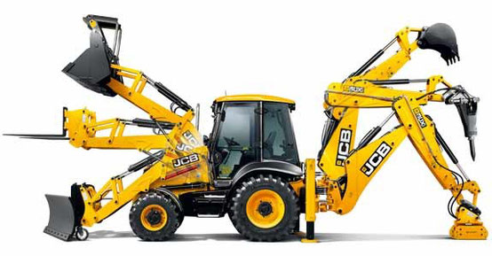
The electronic engine control unit (ECU) and the devices connected to it are distinguished by their robustness and inherently more reliable than connecting wires and connectors.
BEFORE checking or replacing electrical devices, make sure that the correct wires and connectors are installed and that they are functioning properly. In many cases, electrical faults are easily
rectified by identifying faulty wires,
connectors or grounding points. Before carrying out work, it is necessary to disconnect the electrical system by disconnecting the battery. Check the appropriate machine documentation for the
correct procedure.
1 WIRING HARNESS — Visually inspect connecting wires and connectors for signs of damage.
Check the following aspects:
a Shabby wires — intermittent short circuits.
b Cut wires — open circuits. The probable cause is the penetration of wires into the mechanical mechanisms of the machine.
c Broken wires — open circuits. The probable cause is improper routing or bundling of wires without sufficient slack to move the machine.
d Fused wires — intermittent short circuits. The probable cause is contact with the turbocharger or exhaust system.
2 CONNECTORS — Visually inspect the corresponding connectors. Check the following aspects:
a Connection — intermittent short circuits. Make sure the connectors are properly connected and that their locking mechanisms are locked.
b Damage — intermittent open circuit or short circuits. Inspect the connectors for signs of physical damage (such as broken housings or retaining clips). Connectors may melt if they come into
contact with a hot exhaust system or turbocharger. Disconnect the connectors and inspect the pins for damage (such as corroded, bent, or broken pins). DO NOT TOUCH the connector pins on the
electronic engine control unit (ECU). Broken connectors must be replaced.
Contamination — intermittent open circuit or short circuit. Disconnect the connectors and inspect the inside for contamination (usually water, oil, or hydraulic fluid). If necessary,
clean the pins of the connector and the socket with a cotton swab or similar. DO NOT TOUCH the connector pins on the electronic engine control unit (ECU). If there are clear signs of water
contamination, the connectors must be allowed to dry completely before connecting. Inspect all sealing elements carefully for signs of contamination or damage.
3 Grounding Points — Locate grounding points on the engine and machine. Make sure the wire terminals are connected correctly.
Fault codes — structure
The structure of the trouble codes, also known as Diagnostic Trouble Codes (DTCs), has been standardized and represented by a 7-digit code for all road and off-road cars and vehicles. According
to the standard (called J2012), all DTCs must follow the structure below.
1st character — defines the vehicle system (for example, P = power train, C = chassis, U = network)
2nd and 3rd characters — define the subsystem (transmission, CAN network, brakes, etc.)
4th and 5th characters — identify a specific component, circuit or fault (e.g. starter relay)
The 6th and 7th characters are called Fault Type Bytes (FTB) and indicate a specific fault (eg 11 = short to ground). For a complete list, see FTB Numbers below.
Some special trouble codes are defined by an international standard, while others may be defined by individual vehicle manufacturers.
Depending on the specification of the machine, there are several ways to access and display the fault codes that are recorded by the engine ECU:
CAN bus display
The machine can be equipped with a CAN bus display. This display can show all registered codes, eg P0047. All registered codes will be displayed. The operator may have the option to erase the
fault code log. For more information, refer to the relevant machine documentation.
Computer connected to CAN bus
The logged error codes can be accessed using a suitable laptop equipped with appropriate diagnostic software such as the JCB 444 Engine Diagnostics. The computer must be connected to the
vehicle’s CAN bus using a data adapter (DLA).
Once connected, all registered codes can be displayed. The engineer also has the option to erase the fault code log.
JCB Diagnostic trouble Codes list Download
Fault Type Byte Numbers (FTB)
00 No subtype information
02 General fault with signal
04 Internal system malfunction (ECU)
07 Mechanical failure
05 System programming malfunction
09 Component malfunction
11 Short to ground (SC2G)
12 Short to battery (SC2VBAT)
13 Open circuit (OC)
16 Circuit voltage below acceptable threshold
17 Circuit voltage above acceptable threshold
18 Circuit current below the permissible threshold
19 Circuit current above the permissible threshold
1A Circuit Resistance Above Acceptable Threshold
1B Circuit resistance below acceptable threshold
1C Circuit voltage out of range
1F Intermittent circuit operation
23 Permanently low signal
24 Constantly high signal
26 The rate of change of the signal is below the permissible threshold value
27 The rate of change of the signal is higher than the permissible threshold value
29 Invalid signal
2F Intermittent signal
31 No signal (missing / missing)
36 Signal frequency too low
37 Signal frequency too high
38 Wrong signal frequency
45 Malfunction of program memory
46 Calibration / parameter memory fault
47 Malfunction of the self-monitoring system / microcontroller / microprocessor
4B Overtemperature
54 No calibration
64 Signal Acceptance Malfunction
62 Signal comparison fault
72 Actuator stuck open
73 Actuator stuck closed
71 The actuator is stuck
81 Received network data contains error
85 Signal out of range
86 Invalid CAN signal
88 BUS OFF
9A Component or system operating conditions
92 Performance or malfunction
96 Component malfunction or internal malfunction
97 Component or system operation is difficult or blocked
98 Overtemperature of a component or system
When a malfunction is detected, the ECU determines the severity of the malfunction and can take measures to protect the engine or machine from potential damage.
The ECU can take one of the following four actions
Inaction
The ECU has determined that there is no immediate risk to the engine or machine, and that the engine is operating normally, however, remedial action should be taken as soon as possible.
Reduced torque mode:
The power output of the motor has been reduced to reduce motor voltages and temperatures and to minimize motor damage. The machines should be stopped as soon as possible to prevent further
damage.
Emergency mode of movement to the place of repair work:
Engine power output is limited and engine speed is reduced to reduce engine voltages and temperatures and to minimize engine damage. Machines should be stopped as soon as possible to prevent
further damage.
Engine shutdown / delayed engine shutdown
The engine ECU automatically shuts down the engine to prevent impending engine failure.
Fault codes — numeric list
P0001 Fuel volume regulator control circuit open
P0002 Range / Performance of the Fuel Volume Regulator Control Circuit
P0003 Low signal of the control circuit of the fuel volume regulator
P0004 High signal of the control circuit of the fuel volume regulator
P0016 Relationship between crankshaft position and camshaft position
P0087 Too low pressure in the fuel line / system
P0088 Too high pressure in the fuel line / system
P0089 Fuel Pressure Regulator 1 Performance
P0090 Fuel pressure regulator 1 control circuit open
P0091 Low signal of the control circuit of the fuel pressure regulator 1
P0092 High signal of the control circuit of the fuel pressure regulator 1
P0095 Intake Air Temperature Sensor 2 Circuit
P0096 Intake Air Temperature Sensor 2 Circuit Range / Performance
P0097 Low intake air temperature sensor 2 circuit
P0098 High intake air temperature sensor 2 circuit
P0099 Intermittent / unstable intake air temperature sensor 2 circuit signal
P0105 Manifold Absolute Pressure / Barometric Pressure Circuit
P0106 Manifold Absolute Pressure / Barometric Pressure Circuit Range / Performance
P0110 Intake Air Temperature Sensor 1 Circuit
P0111 Low intake air temperature sensor 1 circuit
P0124 High intake air temperature sensor 1 circuit
P0113 High intake air temperature sensor 1 circuit
P0115 Circuit 1 of the engine coolant temperature sensor
P0116 Coolant Temperature Sensor Circuit 1 Range / Performance engine
P0117 Low signal circuit 1 of the engine coolant temperature sensor
P0118 High signal circuit 1 of the engine coolant temperature sensor
P0120 Throttle / Pedal Position Sensor / Switch A Circuit
P0121 Throttle / Pedal Position Sensor / Switch Circuit Range / Performance
P0180 Circuit «A» of the fuel temperature sensor
P0181 Range / Performance of the fuel temperature sensor circuit «A»
P0182 Low signal circuit «A» of the fuel temperature sensor
P0183 High signal circuit «A» fuel temperature sensor
P0190 Circuit «A» of the fuel pressure sensor in the line
P0191 Range / performance of the circuit «A» of the fuel pressure sensor in the line
P0192 Low signal circuit «A» of the fuel pressure sensor in the line
P0193 High signal circuit «A» of the fuel pressure sensor in the line
P0194 Intermittent / unstable signal of the circuit «A» of the fuel pressure sensor in the line
P0200 Injector circuit open
P0201 Injector circuit open — 1st cylinder
P0202 Injector circuit open — 2nd cylinder
P0203 Injector circuit open — 3rd cylinder
P0204 Injector circuit open — 4th cylinder
P0205 Injector circuit open — 5th cylinder
P0206 Injector circuit open — 6th cylinder
P0218 Transmission Fluid Temperature Excess Condition
P0220 Circuit «B» of the sensor / switch of the throttle / pedal position
P0236 Range / Performance of the turbocharger / supercharger boost sensor circuit «A»
P0252 Fuel pump fuel metering range / performance «A» (cam / rotor / injector)
P0253 Low signal «A» of the fuel metering device of the high pressure fuel pump
(camshaft / rotor / injector)
P0254 High signal «A» of the fuel metering pump of the fuel pump (cam / rotor / injector)
P0261 Low signal of the injector circuit of the 1st cylinder
P0262 High signal of the injector circuit of the 1st cylinder
P0263 Contribution / balancing of the 1st cylinder
P0264 Low signal of the injector circuit of the 2nd cylinder
P0265 High signal of the injector circuit of the 2nd cylinder
P0266 Contribution / balancing of the 2nd cylinder
P0267 Low signal of the injector circuit of the 3rd cylinder
P0268 High signal of the injector circuit of the 3rd cylinder
P0269 Contribution / balancing of the 3rd cylinder
P0270 Low signal of the injector circuit of the 4th cylinder
P0271 High signal of the injector circuit of the 4th cylinder
P0272 Contribution / balancing of the 4th cylinder
P0273 Low signal of the injector circuit of the 5th cylinder
P0274 High signal of the injector circuit of the 5th cylinder
P0275 Contribution / balancing of the 6th cylinder
P0276 Low signal of the injector circuit of the 6th cylinder
P0277 High signal of the injector circuit of the 6th cylinder
P0278 Contribution / balancing of the 6th cylinder
P029A The balancing of the 1st cylinder by fuel production is at the maximum limit meaning
P029B Balancing of the 1st cylinder by fuel production is at the minimum limit meaning
P029E Balancing of the 2nd cylinder with fuel production is at the maximum limit meaning
P029F Balancing of the 2nd cylinder with fuel production is at the minimum limit meaning
P02A2 The balancing of the 3rd cylinder by fuel production is at the maximum limit meaning
P02A3 The balancing of the 3rd cylinder by fuel production is at the minimum limit meaning
P02A6 Balancing of the 4th cylinder by fuel production is at the maximum limit meaning
P02A7 Balancing of the 4th cylinder with fuel production is at the minimum limit meaning
P02A8 The balancing of the 5th cylinder by fuel production is at the maximum limit meaning
P02A9 Balancing of the 5th cylinder with fuel production is at the minimum limit meaning
P02A10 Balancing of the 6th cylinder by fuel production is at the maximum limit meaning
P02A11 Balancing of the 6th cylinder with fuel production is at the minimum limit meaning
P02EE 1st Cylinder Injector Circuit Range / Performance
P02EF Range / Performance of the 2nd cylinder injector circuit
P02F0 3rd cylinder injector circuit range / performance
P02F1 4th cylinder injector circuit range / performance
P02F2 5th cylinder injector circuit range / performance
P02F3 6th cylinder injector circuit range / performance
P0335 Crankshaft Position Sensor A Circuit
P0340 Camshaft Position Sensor A Circuit
P0341 Camshaft Position Sensor A Circuit Range / Performance
P0371 Excessive number of pulses «A» high-resolution signal time stamps
P0372 Too few pulses «A» high-resolution signal time stamps
P0374 Lack of pulses «A» high-resolution signal time stamps
P0500 «A» vehicle speed sensor
P0501 Vehicle speed sensor «A» range / performance
P0503 Intermittent / intermittent / high signal «A» of the vehicle speed sensor
P0520 Low Oil Pressure Indicator Light Control Circuit
P0521 Engine oil pressure sensor / switch range / performance
P0522 High oil pressure
P0523 Low oil pressure
P0560 System Voltage
P0562 Low system voltage
P0563 System Voltage High
P0566 Signal «off» («Off») cruise control
P0567 Signal «resume» («Resume») cruise control
P0569 Signal «coasting» («Coast») cruise control
P0570 Signal «acceleration» («Accelerate») cruise control
P0575 Cruise Control Input Circuit
P0602 Control module programming error
P0603 Standby memory error (KAM) of the internal control module
P0604 Error in random access memory (RAM) of the internal control module
P0605 Read-only memory (ROM) error of the internal control module
P0606 Functional malfunction of the security system
P0607 Functional malfunction of the security system
P060A Functional malfunction of the security system
P060B Functional malfunction of the security system
P0612 Engine speed relay control circuit
P0615 Starter Relay Circuit
P0616 Low signal starter relay circuit
P0617 Starter relay circuit high
P061B Functional malfunction of the security system
P061C Functional malfunction of the security system
P061E Functional malfunction of the security system
P0627 Global fuel supply pump malfunction — open circuit
P0628 Global fuel priming pump malfunction — short to ground
P0629 Global fuel priming pump malfunction — short circuit to battery
P062B Functional malfunction of the security system
P062D Fuel Injector Control Circuit Performance
P062E Fuel Injector Control Circuit Performance
P062F Internal control module EEPROM error
P0630 VIN code not programmed or incompatible — ECM / PCM
P0641 Circuit «A» of the reference voltage of the sensor is open
P0650 Malfunction Indicator Light (MIL) Control Circuit
P0651 Circuit «B» of the reference voltage of the sensor is open
P0655 Malfunction Check Engine Light (CEL)
P0656 Fuel level sensor output circuit
P0668 Low signal circuit «A» of the internal temperature sensor PCM / ECM / TCM
P0669 High signal circuit «A» of the internal temperature sensor PCM / ECM / TCM
P0685 ECM / PCM Power Relay Control Circuit Open
P0697 Circuit «C» of the reference voltage of the sensor is open
P1101 Positive malfunction of the line pressure regulation error
P1102 Negative malfunction of the line pressure regulation error
P1103 Malfunction of pressure in the line
P1104 Injector update malfunction
P1105 Injector update malfunction
P1106 Injector update malfunction
P1107 Injector update malfunction
P1108 Injector update malfunction
P1109 Injector update malfunction
P110A Injector update malfunction
P110B Injector update malfunction
P1500 Malfunction of a foot throttle / pedal — emergency mode of movement to the place of repair work
P1501 Foot Throttle / Pedal Malfunction — Reduced Torque Mode
P1503 Hand throttle malfunction — emergency mode of movement to the venue renovation works
P1504 Manual Throttle Malfunction — Low Torque Mode
P1506 Global throttle / pedal malfunction — emergency travel to place repair work
P1509 CAN bus communication error with TSC
P1602 Global Starter Relay Control Circuit
P1603 Functional malfunction of the security system
P1604 Functional malfunction of the security system
P1605 Functional malfunction of the security system
P1606 Functional malfunction of the security system
P2120 Malfunction of channel 1 of the hand pedal signal
P2125 Malfunction of channel 2 hand pedal signal
P2135 Comparison of voltage «A» / «B» sensor / switch throttle / pedal position
P2138 Hand Pedal Signal Mapping Malfunction
P2147 Malfunction (cut off) of the injector voltage source
P2148 Malfunction (cut off) of the injector voltage source
P2226 Barometric Pressure Sensor A Circuit
P2228 Low signal circuit «A» of the barometric pressure sensor
P2229 High signal circuit «A» of the barometric pressure sensor
P2264 Water-in-fuel sensor circuit
P2265 Water in Fuel Sensor Circuit Range / Performance
P2266 Low signal of the water-in-fuel sensor circuit
P2267 High signal circuit of the sensor for the presence of water in fuel
P2269 Water in fuel condition
P250B Engine Oil Level Sensor Circuit Range / Performance
P256A Idle Speed Selector Switch / Sensor Circuit open
P256B Range / Performance of Speed Selector Switch / Sensor engine idling
P256C Low signal of the sensor / switch of the engine speed selector at idle
P256D High signal of the sensor / switch of the engine speed selector at idle
U0001 High speed CAN data bus
U0073 Bus A data transmission control module off
U0100 Lost communication with ECM / PCM «A»
U0121 Lost Communication With Anti-lock Braking System (ABS) Control Module
U0401 Invalid data received from ECM / PCM «A»
U3FFF DTC SAE does not exist — vendor specific data required
P0087 (flashing code 227) the pressure in the fuel rail is too low (for a pump without pressure) The main symptoms
• Strong vibration from the engine.
• Unstable idle
• Output power drop
Exhaust smoke
• There may be too much smoke output
P0088 (flashing code 118) the pressure in the fuel rail is too high
The main symptoms
• Severe engine vibration
• idling is unstable
• Output power drop
• refusal to pump out the gas engine
Exhaust smoke
• The output may be too large
P0089 (flashing code 151) the fuel rail pressure regulator is faulty
The main symptoms
• Severe engine vibration
• idling is unstable
• Output power drop
Exhaust smoke
• The output may be too large
P0090 (flashing code 247) SCV open or shorted fuel pressure regulator
The main symptoms
• Depending on open / short situations, there may be engine stop and / or start
Exhaust smoke
• Smoke output is too high
P0107 (flashing code 71) Atmospheric pressure sensor input low (open or shorted to ground)
The main symptoms
Due to a fallback equivalent altitude of 2000 m (6562 ft)
• Exhaust smoke at high altitude.
• insufficient power at low altitude
P0108 (flashing code 71) Atmospheric pressure sensor input high (+ 5V shorted)
The main symptoms
Due to a fallback equivalent altitude of 2000 m (6562 ft)
• High exhaust smoke
• lack of power at low altitude
P0112 (flashing code 22) intake air temperature sensor malfunction (low voltage error, short to ground, short circuit)
The main symptoms
• White smoke may be emitted during cold start.
P0113 (flashing code 22) intake air temperature sensor malfunction (high voltage supply circuit malfunction)
The main symptoms
• White smoke may be emitted during cold start.
P0117 (flashing code 23) engine coolant temperature sensor malfunction (low voltage error, short to ground, short circuit)
The main symptoms
• At normal temperatures: smoke may be generated,
• At low ambient temperatures at idle speed: there may be an unstable idle speed, difficult to start the engine
P0118 (blinking code 23) The engine coolant temperature sensor gives out overestimated data (shorted to positive or short circuit)
The main symptoms
• At normal temperatures: smoke may be generated,
• At low air temperatures during standstill: there may be an unstable idle,
P0182 (flashing code 211) Fuel temperature sensor malfunction (low voltage faults, shorted to ground)
The main symptoms
Impact on performance.
P0183 (blink code 211) Fuel temperature sensor malfunction (high voltage failure, power circuit open or
short circuit)
P0192 (flashing code 245) fuel pressure sensor (low voltage or short circuit)
The main symptoms
• Possibly stopping the engine
• decrease in output power
P0193 (error code 245) high fuel pressure sensor signal (open or short to positive)
The main symptoms
• the engine may stop
• Output power drop
P0201 (flashing code 271) open circuit in the control circuit of the cylinder 1 injector
The main symptoms
• strong vibration of the engine
• Unstable idle
• Output power reduced
P0202 (flashing code 272) open circuit in the control circuit of the cylinder 2 injector
The main symptoms
• strong vibration of the engine
• Unstable idle
• Output power reduced
• engine failure
P0203 (flashing code 273) open circuit in the control circuit of the cylinder 3 injector
The main symptoms
• strong vibration of the engine
• Unstable idle
• Output power
• refusal to pump out the gas engine
P0204 (flashing code 274) open circuit in the control circuit of the cylinder 4 injector
The main symptoms
• strong vibration of the engine
• Unstable idle
• Output power reduced
• malfunction of the engine
P0205 (flashing code 275) open circuit in the control circuit of the cylinder 5 injector
The main symptoms
• strong vibration of the engine
• Unstable idle
• Output power reduced
• Engine malfunction
P0206 (flashing code 276) open circuit in the control circuit of the cylinder 6 injector
The main symptoms
• strong vibration of the engine
• Unstable idle
• Output power too low
• Engine malfunction
P0219 (flashing code 543) engine overspeed
The main symptoms
Output power drop
P0237 (flashing code 32) boost pressure sensor failure (low voltage error, open circuit)
The main symptoms
smoke
P0238 (flashing code 32) boost pressure sensor failure (high voltage failure, short to minus)
P0335 (flashing code 15) crankshaft sensor malfunction (no signal)
The main symptoms
• Output drop underestimated
• white smoke exhaust
• Engine vibration can be severe
• the engine may stop
P0336 (flashing code 15) crankshaft sensor malfunction (signal failure)
The main symptoms
• Output drop low
• white smoke exhaust
• Engine vibration can be severe
• the engine may stop (when the camshaft position sensor is normalized, it may start with a restart